4x4 Diagnosing

benjaminblazer

Original poster
Member
Mar 25, 2024
89
michigan
When i try to go out of 2wd on my 06 LS 4.2 trailblazer, it blinks for auto, 4H and 4L. When i go back to 2wd the blinking stops and the service light for 4x4 comes on. I try it with the car off and i can hear the actuator click but not sure if that is still the issue? What’s the best way to diagnose the issue? winter coming quick😂
 

TJBaker57

Lifetime VIP Donor
Member
Aug 16, 2015
3,376
Colorado
When i try to go out of 2wd on my 06 LS 4.2 trailblazer, it blinks for auto, 4H and 4L. When i go back to 2wd the blinking stops and the service light for 4x4 comes on. I try it with the car off and i can hear the actuator click but not sure if that is still the issue? What’s the best way to diagnose the issue? winter coming quick😂


Where does the sound you hear come from? There needs to be 2 different sounds from 2 different locations for any shift out of or into 2Hi.

From the front on the right side of the oil pan there's this sound from the axle disconnect...


Then for underneath the center of the truck there is this sound from the encoder/shift/motor....


And for another look & listen here today I was just playing around with some spares at my worktable...

 
  • Like
Reactions: Mooseman

benjaminblazer

Original poster
Member
Mar 25, 2024
89
michigan
Where does the sound you hear come from? There needs to be 2 different sounds from 2 different locations for any shift out of or into 2Hi.

From the front on the right side of the oil pan there's this sound from the axle disconnect...


Then for underneath the center of the truck there is this sound from the encoder/shift/motor....


And for another look & listen here today I was just playing around with some spares at my worktable...

Will check again to listen but using directional hearing it sounds from the center of the car.
 

benjaminblazer

Original poster
Member
Mar 25, 2024
89
michigan
So if you don't hear the longer winding tone of the sound up front on the passenger side of the engine oil pan then you will not get any of the 4WD modes to work. That front axle disconnect is mandatory for any 4WD engagement.
Not hearing sound from which side would be more detrimental?
 

TJBaker57

Lifetime VIP Donor
Member
Aug 16, 2015
3,376
Colorado
Not hearing sound from which side would be more detrimental?


Both devices/sounds are essential.

The front disconnect up by the lower engine couples the front passenger CV axle to the 4 wheel drive system.


The encoder/shift motor under the center of the truck engages the clutch the drive the front propshaft clutch.

Are you not hearing anything up by the engine bay?
 

benjaminblazer

Original poster
Member
Mar 25, 2024
89
michigan
Both devices/sounds are essential.

The front disconnect up by the lower engine couples the front passenger CV axle to the 4 wheel drive system.


The encoder/shift motor under the center of the truck engages the clutch the drive the front propshaft clutch.

Are you not hearing anything up by the engine bay?
I haven’t been able to check it out, i was just wondering what one might be more of a hassle to fix or more expensive. I guess either or could be multiple different reasons though. I’ll be able to check tomorrow and update you, i appreciate it!
 
  • Like
Reactions: TJBaker57

benjaminblazer

Original poster
Member
Mar 25, 2024
89
michigan
Both devices/sounds are essential.

The front disconnect up by the lower engine couples the front passenger CV axle to the 4 wheel drive system.


The encoder/shift motor under the center of the truck engages the clutch the drive the front propshaft clutch.

Are you not hearing anything up by the engine bay?
So just tested, the noise comes from the center of the truck. (Encoder/shift motor i’m guessing) Nothing from the engine bay.
 

TJBaker57

Lifetime VIP Donor
Member
Aug 16, 2015
3,376
Colorado
So just tested, the noise comes from the center of the truck. (Encoder/shift motor i’m guessing) Nothing from the engine bay.


So the front axle disconnect is not engaging.

Power for that device comes from the "4WD" fuse, #48 in the rear fuseblock under the seat.

Next to check would be the wiring down at the device for signs of physical damage, like rodents chewing it up.
 
  • Like
Reactions: Mooseman

benjaminblazer

Original poster
Member
Mar 25, 2024
89
michigan
So the front axle disconnect is not engaging.

Power for that device comes from the "4WD" fuse, #48 in the rear fuseblock under the seat.

Next to check would be the wiring down at the device for signs of physical damage, like rodents chewing it up.
When will power be going to that fuse, when i engage “4L or 4H” or does it have to be something different?
 

TJBaker57

Lifetime VIP Donor
Member
Aug 16, 2015
3,376
Colorado
When will power be going to that fuse, when i engage “4L or 4H” or does it have to be something different?

That fuse, #48, should have power when the key is turned to the RUN position. The engine does NOT need to be running.

The power goes from the fuse down to the electronic actuator on the disconnect. It is a brown wire that connects to terminal D of the 4 pin disconnect actuator harness connector.
 

benjaminblazer

Original poster
Member
Mar 25, 2024
89
michigan
That fuse, #48, should have power when the key is turned to the RUN position. The engine does NOT need to be running.

The power goes from the fuse down to the electronic actuator on the disconnect. It is a brown wire that connects to terminal D of the 4 pin disconnect actuator harness connector.
okay and i’m guessing DC voltage, and would i be able to trace the brown wire under the car or is it ran under my carpet?
 

TJBaker57

Lifetime VIP Donor
Member
Aug 16, 2015
3,376
Colorado
okay and i’m guessing DC voltage, and would i be able to trace the brown wire under the car or is it ran under my carpet?


No need to try tracing the wire unless you discover there is no voltage at the disconnect when there IS voltage at the fuse.

If you DO find such a condition there is at least one midpoint connection that may help limit the possible location of a break.

Often a visual at the disconnect reveals wire damage by rodents or the like.
 

benjaminblazer

Original poster
Member
Mar 25, 2024
89
michigan
No need to try tracing the wire unless you discover there is no voltage at the disconnect when there IS voltage at the fuse.

If you DO find such a condition there is at least one midpoint connection that may help limit the possible location of a break.

Often a visual at the disconnect reveals wire damage by rodents or the like.
Where is the disconnect located? Sorry if you explained this already i just know where the fuse is. Is it right under the fuse box or somewhere where the actuator is.
 

TJBaker57

Lifetime VIP Donor
Member
Aug 16, 2015
3,376
Colorado
Where is the disconnect located? Sorry if you explained this already i just know where the fuse is. Is it right under the fuse box or somewhere where the actuator is.


The "disconnect" is short for "front axle disconnect".

GM calls it the "intermediate shaft bearing assembly".

It is the device which is bolted to the passenger side of the engine oil pan.
 
  • Like
Reactions: Mooseman

benjaminblazer

Original poster
Member
Mar 25, 2024
89
michigan
The "disconnect" is short for "front axle disconnect".

GM calls it the "intermediate shaft bearing assembly".

It is the device which is bolted to the passenger side of the engine oil pan.
Found it. Had some sort of grease on it, still getting voltage from the connector tho so it brings me to a bad actuator?
 

Attachments

  • IMG_9567.jpeg
    IMG_9567.jpeg
    428.4 KB · Views: 2
  • IMG_9568.jpeg
    IMG_9568.jpeg
    382.2 KB · Views: 2
  • IMG_9570.jpeg
    IMG_9570.jpeg
    353.3 KB · Views: 2
  • IMG_9569.jpeg
    IMG_9569.jpeg
    374 KB · Views: 3

TJBaker57

Lifetime VIP Donor
Member
Aug 16, 2015
3,376
Colorado
still getting voltage from the connector tho so it brings me to a bad actuator?

Possibly, but a full diagnosis is not as simple as that.

For the disconnect to activate There needs to be battery voltage on the brown wire and ground on the black wire. This powers the actuator.

So you could check that with a test meter connected between those two.

Then for the activation the TCCM grounds the light blue wire. This is what activates the actuator when the mode switch is moved from 2Hi to any other position (except neutral).

When all 3 of these conditions exist the disconnect actuator should engage.

I have a little video where I do this on a table just to demonstrate and It also shows some of what happens inside the dusconnect.

 
  • Like
Reactions: benjaminblazer

flyboy2610

Member
Aug 24, 2021
568
Lincoln, Ne.
It may be the electrical actuator unit has failed. Those are easy to replace, and not terrifically expensive.

I'm going to add here that if you do wind up needing to replace the disconnect purchase the Dorman unit 600115XD. It comes with an improved cast shift fork that's stronger than the OEM one. At $425 it's a bit pricey, but what isn't nowadays?
To remove the old one, after removing the passenger side CV axle, DO NOT try to just pry the disconnect out of the oil pan! More than one person has wound up a'cussin after breaking the housing off in the oil pan!
Since you already have the truck jacked up and on jack stands, get under the truck and remove the 4 13mm bolts holding the plastic skid plate on. You now have a good view of the back of the disconnect. Remove the bolts holding the disconnect to the oil pan, and from under the truck tap one end of the disconnect up towards the hood. You won't be able to go very far with it, but you don't have to. Now tap the other side up. Repeat the process a couple of times. What you are doing is breaking the corrosion bond that is holding the disconnect to the oil pan. Now tap the disconnect out towards the wheel just a bit, then tap it back in. Tap it out a little farther, tap it back in. Repeat the process, going a little farther out each time, until the disconnect pops free.
Here's a good write up of the internals of the disconnect, and a listing of the GM part numbers for the individual components.

When I replaced mine I purchased new parts to replace anything worn out in the old one. I have a new one in the truck, and a rebuilt one on the shelf.
When you get your new unit, open it up and replace the grease with good high quality grease.
 

benjaminblazer

Original poster
Member
Mar 25, 2024
89
michigan
It may be the electrical actuator unit has failed. Those are easy to replace, and not terrifically expensive.

I'm going to add here that if you do wind up needing to replace the disconnect purchase the Dorman unit 600115XD. It comes with an improved cast shift fork that's stronger than the OEM one. At $425 it's a bit pricey, but what isn't nowadays?
To remove the old one, after removing the passenger side CV axle, DO NOT try to just pry the disconnect out of the oil pan! More than one person has wound up a'cussin after breaking the housing off in the oil pan!
Since you already have the truck jacked up and on jack stands, get under the truck and remove the 4 13mm bolts holding the plastic skid plate on. You now have a good view of the back of the disconnect. Remove the bolts holding the disconnect to the oil pan, and from under the truck tap one end of the disconnect up towards the hood. You won't be able to go very far with it, but you don't have to. Now tap the other side up. Repeat the process a couple of times. What you are doing is breaking the corrosion bond that is holding the disconnect to the oil pan. Now tap the disconnect out towards the wheel just a bit, then tap it back in. Tap it out a little farther, tap it back in. Repeat the process, going a little farther out each time, until the disconnect pops free.
Here's a good write up of the internals of the disconnect, and a listing of the GM part numbers for the individual components.

When I replaced mine I purchased new parts to replace anything worn out in the old one. I have a new one in the truck, and a rebuilt one on the shelf.
When you get your new unit, open it up and replace the grease with good high quality
It may be the electrical actuator unit has failed. Those are easy to replace, and not terrifically expensive.

I'm going to add here that if you do wind up needing to replace the disconnect purchase the Dorman unit 600115XD. It comes with an improved cast shift fork that's stronger than the OEM one. At $425 it's a bit pricey, but what isn't nowadays?
To remove the old one, after removing the passenger side CV axle, DO NOT try to just pry the disconnect out of the oil pan! More than one person has wound up a'cussin after breaking the housing off in the oil pan!
Since you already have the truck jacked up and on jack stands, get under the truck and remove the 4 13mm bolts holding the plastic skid plate on. You now have a good view of the back of the disconnect. Remove the bolts holding the disconnect to the oil pan, and from under the truck tap one end of the disconnect up towards the hood. You won't be able to go very far with it, but you don't have to. Now tap the other side up. Repeat the process a couple of times. What you are doing is breaking the corrosion bond that is holding the disconnect to the oil pan. Now tap the disconnect out towards the wheel just a bit, then tap it back in. Tap it out a little farther, tap it back in. Repeat the process, going a little farther out each time, until the disconnect pops free.
Here's a good write up of the internals of the disconnect, and a listing of the GM part numbers for the individual components.

When I replaced mine I purchased new parts to replace anything worn out in the old one. I have a new one in the truck, and a rebuilt one on the shelf.
When you get your new unit, open it up and replace the grease with good high quality grease.
Thanks for this information, very helpful, will continue to diagnose this week and find out exactly what it is.
 
Last edited by a moderator:

Mooseman

Moderator
Dec 4, 2011
26,306
Ottawa, ON
See if the actuator works outside of the axle disconnect by turning on the ignition and putting it in A4WD/Auto. It it seems to work fine, check if the disconnect works by pushing in the hole where the disconnect goes. It it doesn't move or is very difficult, then look further for a broken disconnect.

Like @flyboy2610 mentioned, don't just reef with a pry bar on the disconnect if it needs to be replaced. Many have broken the disconnect's housing in the oil pan to much grief. Put liberal amounts of penetrating oil and after removing the bolts holding the disco to the pan, try twisting it inside the hole to work it loose.

And how to pull the axle:
 

benjaminblazer

Original poster
Member
Mar 25, 2024
89
michigan
See if the actuator works outside of the axle disconnect by turning on the ignition and putting it in A4WD/Auto. It it seems to work fine, check if the disconnect works by pushing in the hole where the disconnect goes. It it doesn't move or is very difficult, then look further for a broken disconnect.

Like @flyboy2610 mentioned, don't just reef with a pry bar on the disconnect if it needs to be replaced. Many have broken the disconnect's housing in the oil pan to much grief. Put liberal amounts of penetrating oil and after removing the bolts holding the disco to the pan, try twisting it inside the hole to work it loose.

And how to pull the axle:
How can you check if the actuator “works fine”? Will some motion occur, or do i take it off and leave it plugged in?
 

TJBaker57

Lifetime VIP Donor
Member
Aug 16, 2015
3,376
Colorado
How can you check if the actuator “works fine”? Will some motion occur, or do i take it off and leave it plugged in?


I think I can demonstrate. I have a 4WD setup on the workbench right now. Maybe I can take the actuator off the disconnect there and video what it does.

Essentially, there are 2 screws that hold the actuator to the disconnect. Once removed there will be visible a plunger. When the 4WD switch is moved to any 4WD mode should cause the actuator to extend the plunger.

The plunger is actually internally spring loaded. If something is preventing the actuator from extending the plunger the device will still run it's little motor to the extent of travel so it would still make the same noises. It just wouldn't engage the disconnect.

Since you are not hearing the noise of the actuator running you need to determine if the actuator has failed or the wiring to it is damaged.

Have you checked for power specifically on the brown wire with key at the RUN position?
 

benjaminblazer

Original poster
Member
Mar 25, 2024
89
michigan
I think I can demonstrate. I have a 4WD setup on the workbench right now. Maybe I can take the actuator off the disconnect there and video what it does.

Essentially, there are 2 screws that hold the actuator to the disconnect. Once removed there will be visible a plunger. When the 4WD switch is moved to any 4WD mode should cause the actuator to extend the plunger.

The plunger is actually internally spring loaded. If something is preventing the actuator from extending the plunger the device will still run it's little motor to the extent of travel so it would still make the same noises. It just wouldn't engage the disconnect.

Since you are not hearing the noise of the actuator running you need to determine if the actuator has failed or the wiring to it is damaged.

Have you checked for power specifically on the brown wire with key at the RUN position?
Alright so i got some time to jack it up and take a look. Getting voltage from brown and black wire 11.97 to be exact. Un bolted the actuator and flipped on the auto, 4H or 4L and nothing happened. Stuck my finger into a very greasy hole in the disconnect 🤣 
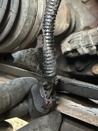
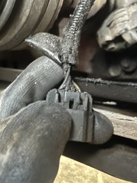
and did not feel anything push but there was a lot of grease as you can see in this picture so maybe my glove was getting caught.
Here is a link to a folder that i have the video of me switching on the 4H switch and then the picture of the disconnect inside.
 

TJBaker57

Lifetime VIP Donor
Member
Aug 16, 2015
3,376
Colorado
Stuck my finger into a very greasy hole in the disconnect 🤣 and did not feel anything push


It does take some force but not a great deal. I often use something as a "poker" like a largish screwdriver to do the pushing with.

I'll have a look at the pictures etc. but did it 'look' like the plunger was extended? Or retracted. When extended there is a small opening at the base of the plunger where the coil spring can be seen.

OK , I looked at your photo and video and that actuator does look retracted to me. The plunger extends for 4 wheel drive.

And that sure is a bunch of grease in there! I have noticed on my spare disconnect that when the hole the actuator pushes into is cleaned out there is a passageway through to the internal cavity of the disconnect. My guess is the grease is coming from there.

We can tell the switch and TCCM is working OK because we hear the transfer case shift motor operate as it should.

So having battery power at the brown, and ground at the black, if you can somehow ground the light blue while the harness is still connected then the actuator should activate and extend the plunger. If it does not then it would appear the actuator has persihed.

The last of the 4 wires there is a black with white stripe. When the actuator plunger is fully exended that wire signals the TCCM that the actuator is in the 4wd position.


If you can ground the light blue wire down at the actuator, with the harness still connected, and the actuator then operates, then there is a wire problem between the actuator and the TCCM (which is in the dash about 10" forward of the headlight switch).
 
  • Like
Reactions: Mooseman

benjaminblazer

Original poster
Member
Mar 25, 2024
89
michigan
It does take some force but not a great deal. I often use something as a "poker" like a largish screwdriver to do the pushing with.

I'll have a look at the pictures etc. but did it 'look' like the plunger was extended? Or retracted. When extended there is a small opening at the base of the plunger where the coil spring can be seen.

OK , I looked at your photo and video and that actuator does look retracted to me. The plunger extends for 4 wheel drive.

And that sure is a bunch of grease in there! I have noticed on my spare disconnect that when the hole the actuator pushes into is cleaned out there is a passageway through to the internal cavity of the disconnect. My guess is the grease is coming from there.

We can tell the switch and TCCM is working OK because we hear the transfer case shift motor operate as it should.

So having battery power at the brown, and ground at the black, if you can somehow ground the light blue while the harness is still connected then the actuator should activate and extend the plunger. If it does not then it would appear the actuator has persihed.

The last of the 4 wires there is a black with white stripe. When the actuator plunger is fully exended that wire signals the TCCM that the actuator is in the 4wd position.


If you can ground the light blue wire down at the actuator, with the harness still connected, and the actuator then operates, then there is a wire problem between the actuator and the TCCM (which is in the dash about 10" forward of the headlight switch).
Is the blue wire one of the 4 that are connected to the actuator, and how can i ground it if it’s plugged in?
 

TJBaker57

Lifetime VIP Donor
Member
Aug 16, 2015
3,376
Colorado
Is the blue wire one of the 4 that are connected to the actuator, and how can i ground it if it’s plugged in?

Yes. It should be a light blue and at one end of the 4 pin connector (opposite the end from the brown wire.

Frequently these things can be done with a slim needle that is slid down alongside the wire in the harness. They make special test leads for this. It is commonly called "backprobing".

let me see if I have a photo, won't be a disconnect actuator but the idea is the same. Here I have backprobed the cooling fan connector at the drivers side of the radiator shroud. If done carefully there is no damage to the harness or wires.

IMG_20200831_102923.jpg
 
  • Like
Reactions: Mooseman

benjaminblazer

Original poster
Member
Mar 25, 2024
89
michigan
Yes. It should be a light blue and at one end of the 4 pin connector (opposite the end from the brown wire.

Frequently these things can be done with a slim needle that is slid down alongside the wire in the harness. They make special test leads for this. It is commonly called "backprobing".

let me see if I have a photo, won't be a disconnect actuator but the idea is the same. Here I have backprobed the cooling fan connector at the drivers side of the radiator shroud. If done carefully there is no damage to the harness or wires.

View attachment 114844
Okay i understand now, and lastly what do you mean by ground it tho? So i leave it plugged in with the plunger out and visible. Switch on the 4wd to auto or 4h or 4L. Then do what exactly? Do you just mean check for voltage? A little confused here.
 

TJBaker57

Lifetime VIP Donor
Member
Aug 16, 2015
3,376
Colorado
Sometimes a picture is worth a thousand words. Some pictures aren't worth doodley-squat!!

Hopefully these pictures and a video is worth something.

Here I will put a couple images showing where I insert my needle/probe. I couldn't get it shown well in video.

20241029_132135.jpg20241029_132200.jpg20241029_132122.jpg

And then there is video...


Last edited:

benjaminblazer

Original poster
Member
Mar 25, 2024
89
michigan
Sometimes a picture is worth a thousand words. Some pictures aren't worth doodley-squat!!

Hopefully these pictures and a video is worth something.

Here I will put a couple images showing where I insert my needle/probe. I couldn't get it shown well in video.

View attachment 114846View attachment 114847View attachment 114848

And then there is video...


Wow, that video was perfect for explaining it. Ordered a probing set will be here tmr and going to test!
 

TJBaker57

Lifetime VIP Donor
Member
Aug 16, 2015
3,376
Colorado
Damnit ! I keep posting to the wrong thread !!


Wow, that video was perfect for explaining it. Ordered a probing set will be here tmr and going to test!


I had a moment just now about how I can test my benchtop setup out on limited power!

I unplugged the motor and jumpered in a taillight bulb!

It worked!

PXL_20241029_234233085.jpg
 
  • Like
Reactions: azswiss

benjaminblazer

Original poster
Member
Mar 25, 2024
89
michigan
Sometimes a picture is worth a thousand words. Some pictures aren't worth doodley-squat!!

Hopefully these pictures and a video is worth something.

Here I will put a couple images showing where I insert my needle/probe. I couldn't get it shown well in video.

View attachment 114846View attachment 114847View attachment 114848

And then there is video...


Alright so if you take a look at this video in my google drive folder, i do pretty close to the same thing you do on your bench. No extension visible, car is in the on position. Do i have to have the 4wd switched to auto, 4H, or 4L to be able to ground the blue wire? I thought you mentioned i didn’t so i just turned the key to the on position like you did in the video.
Let me know my next steps i appreciate all your help so far!
Link to the drive: https://drive.google.com/file/d/1icnqjDS2KDu75nJtUCOJtamS0ZgnBxTQ/view?usp=drivesdk
 

TJBaker57

Lifetime VIP Donor
Member
Aug 16, 2015
3,376
Colorado
@benjaminblazer

Correct, the key should be ON and the 4WD switch in 2Hi.

By any chance did you try other points to attach your probe lead to ground? The spot seen in the video doesn't look all that clean. It needs to make contact to bare unpainted metal.

And of course it is possible that the actuator is indeed bad.
 

budwich

Member
Jun 16, 2013
2,214
kanata
withstanding the test that you are trying to do, I think there are some "easier" ones that might help.... maybe.

Of course, "easy" is in the eyes of the beholder, and in this case I am only "beholding" a computer display and service manual... :smile:

IF I understand things right, the axle actuator has a voltage (BN wire / pin d), a switch signal (bk/wh, pin c), ground (bk, pn b) and a control signal (lt bu, pin a). Although your tests seems OK, there seems to be a question on "contact" in terms of whether it is good enough to cause something to happen. I would suggest that perhaps you do a "simple resistance" test. This can be done with the unit disconnected at the cabling. IF I follow things, you are expecting a ground on pin A to cause something. IF that true, then a resistance measurement from pin A to pin D on the actuator should be reading some form of the actuator solenoid and should provide some form of reading. This will tell you if the actuator had the potential electrical base "sanity" to operate when the right conditions are applied (as you were trying to do). However, this method takes out any "guess work" about whether you are applying those conditions "well". Similarly, a resistance reading across pins B and C will tell you if the "feedback" circuit of the actuator has the potential electrical capability to provide the system with "feedback".

I may have missed this in the postings... but have you done these kinds of checks?
 

benjaminblazer

Original poster
Member
Mar 25, 2024
89
michigan
withstanding the test that you are trying to do, I think there are some "easier" ones that might help.... maybe.

Of course, "easy" is in the eyes of the beholder, and in this case I am only "beholding" a computer display and service manual... :smile:

IF I understand things right, the axle actuator has a voltage (BN wire / pin d), a switch signal (bk/wh, pin c), ground (bk, pn b) and a control signal (lt bu, pin a). Although your tests seems OK, there seems to be a question on "contact" in terms of whether it is good enough to cause something to happen. I would suggest that perhaps you do a "simple resistance" test. This can be done with the unit disconnected at the cabling. IF I follow things, you are expecting a ground on pin A to cause something. IF that true, then a resistance measurement from pin A to pin D on the actuator should be reading some form of the actuator solenoid and should provide some form of reading. This will tell you if the actuator had the potential electrical base "sanity" to operate when the right conditions are applied (as you were trying to do). However, this method takes out any "guess work" about whether you are applying those conditions "well". Similarly, a resistance reading across pins B and C will tell you if the "feedback" circuit of the actuator has the potential electrical capability to provide the system with "feedback".

I may have missed this in the postings... but have you done these kinds of checks?
What about of resistance am i looking for between the pins?
 

benjaminblazer

Original poster
Member
Mar 25, 2024
89
michigan
withstanding the test that you are trying to do, I think there are some "easier" ones that might help.... maybe.

Of course, "easy" is in the eyes of the beholder, and in this case I am only "beholding" a computer display and service manual... :smile:

IF I understand things right, the axle actuator has a voltage (BN wire / pin d), a switch signal (bk/wh, pin c), ground (bk, pn b) and a control signal (lt bu, pin a). Although your tests seems OK, there seems to be a question on "contact" in terms of whether it is good enough to cause something to happen. I would suggest that perhaps you do a "simple resistance" test. This can be done with the unit disconnected at the cabling. IF I follow things, you are expecting a ground on pin A to cause something. IF that true, then a resistance measurement from pin A to pin D on the actuator should be reading some form of the actuator solenoid and should provide some form of reading. This will tell you if the actuator had the potential electrical base "sanity" to operate when the right conditions are applied (as you were trying to do). However, this method takes out any "guess work" about whether you are applying those conditions "well". Similarly, a resistance reading across pins B and C will tell you if the "feedback" circuit of the actuator has the potential electrical capability to provide the system with "feedback".

I may have missed this in the postings... but have you done these kinds of checks?
Also pins at the connection of the actuator or pins at the wire?
 

budwich

Member
Jun 16, 2013
2,214
kanata
You are looking to test at the actuator. The pin "numbers" that I gave are in relation to what you see on the wire connector as there might not be any pin numbering visible on the actuator.

You are looking for some resistance... the actual values are not that important... what's important is that there are some values and not "open circuit".
 
  • Like
Reactions: benjaminblazer

Forum Statistics

Threads
23,801
Posts
643,553
Members
19,506
Latest member
cantaris

Members Online