4.2 Engine Rebuild

mrrsm

Lifetime VIP Donor
Supporting Donor
Member
Oct 22, 2015
8,192
Tampa Bay Area
@Sparky ... Yes... it would seem very logical to use the High Grade Steel Studs and Bolts from ARP... but the problem in doing so involves how much the Aluminum Block Substrate is capable of EXPANDING and CONTRACTING. Ordinarily... Cast Iron and Steel expand and contract at the rate of 1/64,000,000" per degree Fahrenheit as it either Heats up ...or Cools down. Aluminum, however responds to those increases and decreases in temperature with a much greater level of Expansion and Contraction... such to the extent that with RIGID STEEL STUDS AND BOLTS... the affect of such a restrictive holding force would either damage the Aluminum Mating Points and Strip Out the Bolt Holes and Thread lines inside the softer Aluminum Block...or simply fracture and break off the Hardened Steel Fasteners.

The GM Engineers decided to give a kind of "Systemic Stretchability" to the Aluminum Engine Block and Head that is allowed because the TTY Fasteners STRETCH when the Engine Block and Head HEAT UP... and have a kind of "Elastic Rebound" to return to their more relaxed state when the Engine Cools Down... and yet...STILL maintain their Torque and Gripping Power.

This entire Atlas Engine behaves more like a "Metal Balloon" in this regard and this gives a wonderful reason of what happens to the Non-TTY Fasteners that repeatedly Snap Off and fail that hold the Rigid Cast Iron Exhaust Manifold alongside the more Balloon like Aluminum Head. Part of the reason they break off is because these large, very different metal surfaces expand and contract at markedly different rates and the Bolts holding them together lack the matching elasticity of the HEAD BOLTS, and CRANKSHAFT CRADLE BOLTS... and all too often...Fail as the result.
 

Sparky

Member
Dec 4, 2011
12,927
Right. In some cases on other engines with an iron block but aluminum heads, you have a higher risk of head gasket failure for that reason. I figure the exhaust manifolds are bad for breaking bolt heads because of higher and more drastic heat changes being on the exhaust side and in direct contact with the hot exhaust.

But, when you're bolting two aluminum hunks together though (the block and the heads) that may not be as much of a concern. I know people have used ARP studs on LS engines (which are aluminum) without issue for years.

Just pondering, that's all. I know the main physics behind it all with the different expansion and contraction rates.
 
  • Like
Reactions: mrrsm

mrrsm

Lifetime VIP Donor
Supporting Donor
Member
Oct 22, 2015
8,192
Tampa Bay Area
Of course... Please take no offence... your rhetorical question prompted a response meant more for other inquisitive Post Readers coming to see @m.mcmillen 's work... just in case they too are wondering about the issue as well.

Don't get me wrong... I too sought out a Complete Set of ARP Fasteners for the LL8 Engine or from any other source to gain more "Peace of Mind" for the re-assembly as you earlier suggested... But my research into the matter prompted this discovery of "why" none were available.
 
Last edited:

m.mcmillen

Original poster
Member
Apr 29, 2016
556
Wisconsin
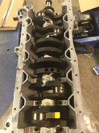
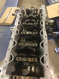
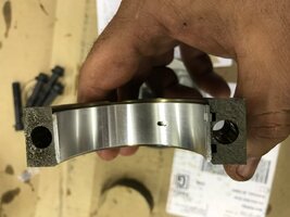
I was able to do a bit of work today. I got the crankshaft installed. I made a bit of a mistake when I bought my main bearing bolts. I bought a Dorman kit and didn't pay attention to how many bolts are in it. Yeah, 10 bolts. There are 14 main bearing cap bolts. I ordered 4 from the dealer and should have them tomorrow. I put in four of the old bolts but didn't torque them down.

Something to keep in mind while installing the caps is that they must go in the position they came from and faced the correct way. Luckily, the caps in this engine are marked 1-7 and with an arrow that goes pointed toward the front of the engine.

IMG_0476.JPG
IMG_0479.JPG

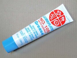
I used Lubriplate No. 105 for my assembly grease and I used a light coating of 5W30 oil on the threads of the bolts.
Z0158.jpg

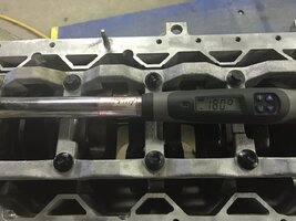
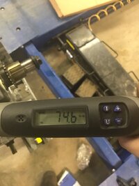
The torque spec was 18 foot pounds on the first pass and an additional 180 degrees for the second pass.
IMG_0481.JPG
IMG_0482.JPG
What I like about this torque wrench is that once I reach the degrees required, it will tell me what the final torque is. That is pretty handy so you can see if any bolts too significantly more or less torque to turn the degrees.

Hopefully tomorrow I will get all of the pistons installed.
 

m.mcmillen

Original poster
Member
Apr 29, 2016
556
Wisconsin
So, I had a bit of a hiccup with the main bearing cap bolts.

I installed 10 Dorman bolts and 4 AC Delco bolts. The Dorman bolts ended up with a final torque of 70-75 foot pounds. The AC Delco bolts ended up with a final torque of 45-50 foot pounds. I just ordered 10 more AC Delco bolts and I'm going to put those in and see what I get.

I don't think that I have a problem with the threads in the block. I'm thinking that the material that the bolts are made out of are not the same. I'm going to all the same bolt to get the same amount of clamping force all the way across the caps.
 
  • Like
Reactions: xavierny25

Sparky

Member
Dec 4, 2011
12,927
That sounds like a good idea.
 

mrrsm

Lifetime VIP Donor
Supporting Donor
Member
Oct 22, 2015
8,192
Tampa Bay Area
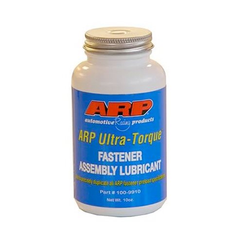
A while ago... we were discussing the subject of why the TTY Bolts might Benefit from using the ARP Thread Lubricant. The ARP Fastener Assembly Lubricant is available here... if you decide you want to use it during your Build:

https://www.amazon.com/dp/B004XJRFCK/?tag=gmtnation-20
41sjA1NRV-L.jpg

Also... I recall seeing this FelPro PDF that covered the basis for recommending its use... and I think it also has some additional data that will give you some Peace of Mind about any issues with possible Thread Damage concerning the two different torque issues with the GM OEM vs The Dorman Fasteners in the bottom end of the engine. I’m thinking here (...and I also have my Fingers and Toes Crossed) that you are going to be Okay... But examining the contents of ALL the Bolt Holes for any Loose or Semi-Circular Particles or Pieces of the Aluminum Block Thread Lines will be conclusive. If God Forbid... you do find any problems... TIME-SERT has a Specific Repair Kit for dealing with any such issues. PLEASE READ THE COMMENTS WAY DOWN AT THE BOTTOM OF THE PDF AS MADE BY MR. ROBERT ALAN ...AS HIS CONCERNS ARE PARALLEL TO YOUR PRESENT SITUATION.

http://www.felpro-only.com/blog/proper-installation-use-t-t-y-bolts/

One other observation about your Excellent Images...If you look real close in your First Two Photos...you can see the Marks in the Flat Case Flanges at the Back of the Block where the two Crankcase Bolts made contact to separate the Crankcase from the Block. Wow... What a Tall, Cool Drink of Water those Pictures are in an otherwise Desert-Like Dearth on the Internet of never getting to see these things so up close and clear. Nice Work!

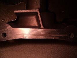
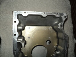
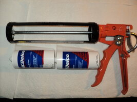
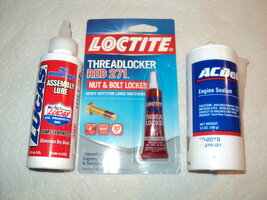
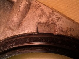
When it come time to re-install the Crankcase... Even Permatex Ultra---Whatever RTV will NOT work as well as the GM OEM RTV shown below... Also... The inlaid grooves in the Upper Centre Flange areas of the Crankcase are remarkably difficult to completely clean out as these images show of a Flange surface that was allegedly "Perfectly CLEAN...". It seemed that no matter how many times I dug that Old Stuff out of the Alignment and Stabilizing Slots... much more was deeper down inside of each one. I had to be very careful not to damage the Aluminum with my S/S Knife and Dental Pick.

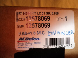
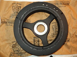
When the time comes to install your Harmonic Balancer... be mindful that there are Two Flavours of this part...and the updated one MUST have the Unique GM OEM Spacer shown in the attached image in order to keep a proper lateral reference of the Crankshaft externally or else the HB could impact and grind against the outside of the Timing Chain Cover ...even with Brand New Thrust Bearings installed onto the Crankshaft inside of the Engine. If the New HB does not come with it pre-installed as you can see here... then it will be an important distinction to investigate whether or not it is necessary to install one...before the HB gets re-installed:DSC03855.jpg DSC03838.jpg DSC03835.jpg DSC03834.jpg DSC03734.jpg DSC03733.jpg DSC03732.jpg DSC03671.jpg DSC03606.jpg DSC03605.jpg DSC03604.jpg DSC03603.jpg
 
Last edited:

m.mcmillen

Original poster
Member
Apr 29, 2016
556
Wisconsin
I just pulled one of each brand bolt from the main bearing caps. I took the sharp edge of a file and started working it on the bolt. On each bolt I was able to cut a little groove in. I noticed though that even though the AC Delco bolt didn't seem a whole lot easier to do it on I could see the metal filings falling off the bolt as I was using the file. I didn't see that on Dorman bolt.
I called the dealer and ordered 14 new bolts from them. I'm planning pulling them all and inspecting the threads carefully. I did stick a bore scope down in the holes and I didn't see anything alarming. But, better to be safe than sorry on this critical part of the engine.
Something that I should have done but I forgot about when I put the bolts in was to put a bit of oil on the flange of the bolt. These bolts don't have washers on them so they were turning on the bearing caps dry. I'll look at those carefully tomorrow and make sure they're not in too bad of shape and see if they need cleaned up a bit.

The machine shop called me this morning and said that my head was all done so I'm going to pick it up tomorrow and hopefully get the engine mostly assembled this weekend.

Edit:
Something worth noticing on Dorman bolt (lower part of the picture) is the extra length they added past the threads. The bolt is that much longer than the AC Delco bolt. There is also more thread on the bolt.
 

Attachments

  • main bearing bolt.JPG
    main bearing bolt.JPG
    81.1 KB · Views: 34
Last edited:

Mooseman

Moderator
Dec 4, 2011
25,996
Ottawa, ON
The ACDelco bolt should be the same as the dealer bolt. Dorman, who knows what they are. They could be OK but with this engine, you never know. Heck, it's even picky on spark plugs so imagine bearing cap bolts. With the dealer bolts, you will be 100% certain they are correct.
 
  • Like
Reactions: Redbeard and mrrsm

m.mcmillen

Original poster
Member
Apr 29, 2016
556
Wisconsin
I'm buying the bolts directly from the dealer. They are pretty quick to get anything for this engine if they don't have it and I get a pretty good discount from them too. I buy quite a bit of stuff from them for work.

Usually I'm pretty cautious about buying stuff from Dorman. I guess it was a weak moment.
 
  • Like
Reactions: mrrsm

m.mcmillen

Original poster
Member
Apr 29, 2016
556
Wisconsin
I picked up my head today and paid my bill at the machine shop. $600 for the work on the head and block. Not too bad I guess. As of now I'm up to about $1600 in parts.
 
  • Like
Reactions: mrrsm

mrrsm

Lifetime VIP Donor
Supporting Donor
Member
Oct 22, 2015
8,192
Tampa Bay Area
If it is of any consolation to you... unlike the majority of the Owners/Members/Non-Members suffering with failed GM Atlas 4.2L Engines found inside a whole panoply of Makes and Models of SUVs... with only a single path to solve this problem by having to pay anywhere from $3000 to $5,000 for a Re-Manufactured Engine, plus the Labour for the R&R... Your Skill Set allows you to fix all of these issues yourself. And when the time comes to Pre-Oil and Start Up your Hand-Crafted Engine... You will be able to draw upon the Great Personal Satisfaction that you will feel for having done all of this... on your own "Steam". Not many people in the World can say that... and save a great deal of money in the doing of it besides. ;>)
 
  • Like
Reactions: Redbeard

m.mcmillen

Original poster
Member
Apr 29, 2016
556
Wisconsin
I keep reminding myself of the money I'm saving. I'm glad that I took it apart when I did or I would be spending more on machine work or even another block. I think that those pistons would have really beat those walls up over time. I love building engines but it is more fun to do when someone else is paying for it!

I guess it is a good thing that I have an over-senisitivty to noises. Any noise that sounds the least bit abnormal drives me nuts.

This knocking noise was getting bad enough that people were mentioning it to me. I have been hearing it for about 9 months or so but it got a lot louder the last week that I drove it.
 
  • Like
Reactions: Redbeard and mrrsm

m.mcmillen

Original poster
Member
Apr 29, 2016
556
Wisconsin
I bought the new main bearing bolts from the dealer and they came in late Friday afternoon. I was able to work on the engine a little bit on Saturday.

I pulled all of the bolts back out and examined all of the holes. I didn't see anything out of the ordinary so I went ahead and put the new bolts in. Everything torqued evenly this time. The highest final torque I had was 55 and the lowest was 51. I'm pretty happy that this worked out well.

The torque spec on these again is 18 foot pounds plus 180 degrees. Here is the sequence:
torque sequence.gif

I've never seen a manual state to do this but here is what I do when I torque something that has this many bolts. I put all of the bolts in and run them in until the head touches the surface. Then, I torque them all in sequence and then I keep doing the sequence over and over in this instance, 18 foot pounds, until none of them move again. On these main bearing bolts, I think I did the sequence about 5 times before they wouldn't turn anymore with the torque wrench set to 18 foot pounds. I did the final pass at 180 degrees. I used a VERY LIGHT coat of 5W30 oil on these.

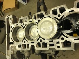
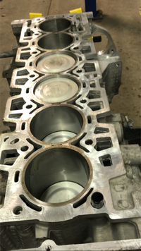
I was able to install all of the pistons as well. Notice that these connecting rods have "cracked caps". The rods are cast and then they are broken in the middle. With this type of rod you need to make sure that you do not get the caps mixed up. or the rod will not go back together as it should. Also, the rod has to be turned the correct direction. If you look at the picture below, the way you can tell if the rod cap is in the correct direction is if all of the etched numbers are on the same side.
IMG_3463.JPG
IMG_3541.JPG

I forgot to take pictures of installing the new pistons to the rods or installing the rings onto the pistons. Sorry @MRRSM ! Basically, install a new wrist pin retainer, oil up the wrist pin bushing and the pin, line everything up and slide the new pin in. Once the new pin is in, install the other retainer.

When you install the piston rings start with bottom rings and work your way up. Be extremely careful with the top two rings as they are very brittle and can break easily. You can buy a ring expander for putting the rings on but I usually just do them by hand. Made sure to stagger the rings! You don't want the ring gaps to line up or you will have compression/oil consumption issues.

Next, install the pistons into the cylinder. I put a coat of oil on the cylinder wall and a coat of oil on the piston and rings. Don't use too much oil. The rings will seat faster with less oil on the walls. I've heard of some that put them in dry but I can't bring myself to do that. Use a ring compressor and note that if your compressor has a taper to it or not. Mine has "bottom" etched into it.

IMG_3542.JPG
IMG_3543.JPG

Before installing a piston I put the two crankshaft journals for the pistons I'm installing all the way down.

Make sure that the piston is straight in the bore. There is not much room for it to be very crooked. Also, note the position of the notch in the piston. The notch goes pointed toward the front of the engine. Next, I use a the rubber handle of my dead blow hammer and tap VERY LIGHTLY on the top of the piston. You don't want the piston to go into the cylinder in one hit. There's always the possibility that a ring might pop out or something and you could break it.

Once the piston is all the way in the bore, I reach down and grab the bottom of the connecting rod and guide it onto the journal as I lightly tap the top of the piston. You don't want to go to fast and knick the crankshaft. Before you install the cap, put some assembly grease on the bearings.

The torque spec for the connecting rod bolts is 18 foot pounds plus 110 degrees. I just finger tighten all of the connecting rod bolts and then when all of the pistons are installed, I flip the engine over and tighten the connecting rods in pairs. It is a good idea to do this so when you go to turn the crankshaft to access the bolts, you can tell if something is binding up and you can narrow down where the problem is (I learned this the hard way once).

Here, you have everything installed and I gave the crankshaft a few rotations to make sure that everything works smoothly.
IMG_3548.PNG
 

mrrsm

Lifetime VIP Donor
Supporting Donor
Member
Oct 22, 2015
8,192
Tampa Bay Area
This information is magnificent! Thanks for posting the majority of the assembly work images. I completely agree with your method of using the Gradual Torque Down Procedures (Now HERE is a Man after my own heart!) drawing down everything in multiples by following the Torque Tightening Pattern sequentially until they all stabilized at 18 Ft Lbs before the Final TTY at 180 Degrees. I also like the fact that you did not spare using Plenty of Lubri-Plate Assembly Grease instead of the usual few drops of oil that get smeared casually on the Bearing Surfaces with Dirty Fingers.

You have probably done all of these things... But since you mentioned early on that ordinarily you perform much of your Engine Re-Building Work without mentioning and itemizing things you believe are a "given" during these procedures... and since this is such a rare kind of build... would you mind my asking a few additional questions about things that many will not know to ask about on critical aspects of the build?:

Did you use STD Rings like the Pistons Markings as STD since they just cleaned up the block by honing... or were they 0.010 Oversized... and did you check the Ring Gaps or have to file any down?

Did you use Plasti-Gage to measure all of the Main and Con-Rod Bearing Clearances and were they also STD or was the Crankshaft Turned?

Did you use a Block of Wood and Mallet to Tap the Crankshaft Fore and Aft lightly first... and then Checking the Thrust Bearing Clearances for Acceptable End Play?

Did you Hand Spin the Crankshaft after completing the installation of the Main Caps and Cradle- Torque and TTY... but BEFORE fitting the Connecting Rods and Pistons? If so... Did the Crankshaft spin very freely or was it "snug" feeling?

Did the Machine Shop "Deck" the Block enough to require any change in the thickness of the MLS Gasket to adjust for any changes in Quench and Compression Ratio Increase?
 
Last edited:
  • Like
Reactions: 808

m.mcmillen

Original poster
Member
Apr 29, 2016
556
Wisconsin
I used standard rings and pistons. The machinist said that he hardly took anything out of there and that the cylinders were still within spec for standard sizes.

I did not need to get the crank turned down any. Everything on the journals measured within spec. The bearings I took out looked almost as good as the new ones. Hats off to the previous owner for taking good care of the oil at least. I also had checked the oil pressure before I took the engine apart and it was really good so I'm not worried about the bearings. I didn't use any plasti-gauge. I did install all new bearings though.

I didn't check the end play of the crankshaft. Although, I'm not worried about that. The thrust bearing didn't show any signs of wear and neither did the crankshaft.

I did turn the crankshaft by hand after torquing everything turned nice and free. It didn't turn overly easy but I was able to grab the end of it and turn it. Even with all of the pistons installed I can still turn it pretty easily with a 3/8 ratchet.

The machinist checked the block and the head for flatness and both were still straight so they didn't need shaved any. This may be a good time to mention that taking the head off and using a reversed torque sequence to keep the head from warping when removing the head bolts is a good idea and works.
 
  • Like
Reactions: 808 and mrrsm

mrrsm

Lifetime VIP Donor
Supporting Donor
Member
Oct 22, 2015
8,192
Tampa Bay Area
That is all Great News! I was doing some calculations of the design of the Piston to Cylinder Volume conditions vs. the Length of Stroke and its worth noting that now I can understand how well the cylinders can really resist wear and tear within this engine while not having to deal with the typical problems V6 and V8 Engines can suffer with the lower cylinder areas "ovaling out" so much.

The Atlas Engine is kind of a brilliant design in this respect and it is no wonder these engines can go for 250,000 Miles and more with proper lubrication, Oil Changes and care and decent treatment when the power-plant is running. I'd give my Eye Teeth to be able to watch you working on this motor! Thanks for the thorough updates... and so here is even more information that will help people to remember that it was The legendary @m.mcmillen ...who is creating a lasting and useful record of these events and actions!
 
  • Like
Reactions: 808

m.mcmillen

Original poster
Member
Apr 29, 2016
556
Wisconsin
Engine technology has come a long way over the years. I think a big factor is that they have found that piston rings don't need as much tension as they thought. There was a time that if you wanted to rebuild an engine that you would have to have a ridge reamer to be able to get the pistons out.

I've never personally seen it first hand but I have heard about it from people that worked on cars back in the 50's-60's. All of the "machining" that the pistons were doing had to have been dumping some metal into the oil. It is no wonder that the engines would be doing good to last 100,000 miles.
 

mrrsm

Lifetime VIP Donor
Supporting Donor
Member
Oct 22, 2015
8,192
Tampa Bay Area
Well... If you allow this slight Thread Jack... I would fall into that category of people with a lot of experience with such motors. This list follows this Trail of Engine Rebuilding and Repairs in vehicles I have owned at one time or another...or now...over my long life time:

English Morris Minor
4 Cylinder CID ???

Volvo 544
1.8L I-4 -2BBl Carb

Ford
292 CID V8 "Y" Block Ford Fairlane 500
260 CID 1964.5 Mustang (This one had a "Falcon" Dashboard Factory Installed in it!)
289 CID 1968 Mustang
302 CID 1970 Mustang

Chevrolet:
265 CID V8 SBC Chevy Nova
283 CID V8 SBC Chevy Impala
307 CID V8 1983 Chevrolet Camaro Z-28
307 CID V8 1983 Chevrolet Camaro Berlinetta
327 CID V8 SBC 1955 Chevrolet Bel-Air 2 Door
350 CID V8 SBC 1987 Chevrolet Z-28 Rag Top
350 CID V8 SBC 1993 Chevrolet Camaro Z-28 LT-1 1992 Corvette Engine
350 CID V8 SBC 1994 Chevrolet Z-28 Rag Top
396 CID V8 BBC 1955 Chevrolet Bel-Air 2 Door
207 CID V6 3.4L 6/60 1994 Chevrolet Camaro RS
GM 4.2L I-6 Atlas Engine 2002 Chevrolet Trailblazer LS (On-Going Re-Build)
GM 4.8L V8 2003 Chevrolet Silverado (Gifted to my Son)
GM 5.3L V8 2000 Chevrolet Silverado (Daily Driver)
Aluminum Cane: (Daily Driver)

Collapsible... Tubular "0" CID with a Wide Tire Tip... LOL

...'nuff said...
 
Last edited:
  • Like
Reactions: 808 and m.mcmillen

07TrailyLS

Member
May 7, 2014
423
Toledo ohio
This thread is perfect. 2 pages worth of really great material. Very straightforward and easy to understand. Damn thing should be stickied at the top of the engine drivetrain section. Great job mcmillen
 
  • Like
Reactions: 808

mrrsm

Lifetime VIP Donor
Supporting Donor
Member
Oct 22, 2015
8,192
Tampa Bay Area
Since you are headed towards re-assembly... I thought I would drop in the essence from a posting from another site that is significant in the case of your 2003... because it provides the comprehensive data about the upgrades GM introduced for your Engine...and it includes the things to be mindful of if purchasing components that, if made for the 2002 4.2L Engines...will be a variation that might qualify as a "step backwards" in performance. I think this reference information will prove useful:

Vortec 4200 (LL8)

OVERVIEW

When it was introduced in the 2002 Chevrolet Trailblazer, GMC Envoy and Oldsmobile Bravada, the Vortec 4200 marked the return of an inline six-cylinder engine to Powertrain’s lineup for the first time since the mid-1980s. While the industry at large had turned away from the line six, GM recognized that given careful design and development, the inherent advantages of inline six cylinder architecture were perfect for the new millennium. Yet with the technical sophistication of premium passenger car engines and the power of competitors’ V8s, the Vortec 4200 is no ordinary in-line six. Its flexible architecture builds the foundation for a range of 4, 5 and 6 Cylinder in-line engines, maximizing the return on corporate investment while exceeding customers’ performance expectations.

2003 Model Year Summary

· Polymer-Coated Pistons
· Oil Pump Refinements
· Cam-Chain Tensioner Improved
· Crankshaft Torsional Dampener Revised
· Head Gasket Refinements
· Spark Plug Design
· Calibration Changes to Improve Performance

FULL DESCRIPTIONS OF NEW OR CHANGED FEATURES

POLYMER-COATED PISTONS

Pistons in the Vortec 4200 (LL8) are now finished with a polymer coating. The polymer limits bore scuffing, or abrasion, of the cylinder wall over time from the piston’s up-down motion. The coating also dampens noise generated by the piston’s movement within the cylinder. The result for the customer is less engine wear, improved durability and quieter operation.

OIL PUMP REFINEMENTS
The oil pump has been revised to reduce operational noise. The pump has the same capacity as its predecessor, but its inlet and outlet ports--the passages where oil enters and leaves the pump--have been refined. The ports are now smoother, with no sharp edges. This design minimizes the hydraulic sound generated by many oil pumps and reduces overall engine noise.

CAM-CHAIN TENSIONER IMPROVED
The automatic cam-chain tensioner, one of the Vortec 4200's key maintenance reducing features, has been enhanced for even quieter operation. The cam chain connects the camshafts with the crankshaft, and turns the cams as the crank rotates. Even the most durable chains stretch with time, and in many engines must be adjusted or replaced at scheduled intervals.

The hydraulically operated cam-chain tensioner keeps proper tension on the chain, even as it stretches with mileage, eliminating the need for adjustment and ensuring maximum efficiency over the life of the engine. Such devices are particularly challenging to develop for all-aluminum engines such as the 4.2L, because aluminum tends to expand and contract with hot-cold cycles more than conventional cast iron. As a result, the tensioner must be both flexible and extremely accurate to maintain perfect tension on the chain. After a thorough analysis of test and field data, engineers have developed more ratcheting range into the tensioner to precisely account for aluminum’s expand-contract cycles. The previous tensioner design was adequate, but the new one further reduces cam-drive noise.

CRANKSHAFT TORSIONAL DAMPENER REVISED
The Vortec 4200's nodular cast iron crankshaft is now equipped with a single-frequency torsional dampener rather a dual-frequency dampener. With the Vortec 4200’s long stroke, and the length of its crankshaft relative to the cranks in V-engines or inline fours, torsional vibration (in effect a wave of flexing from one end of the shaft to the other) can be significant.

At launch, this flex was addressed with a dual frequency harmonic dampener. Three steel discs, separated by two injection-molded rubber rings, were attached directly to the front of the crank, counteracting the inherent flex and virtually eliminating vibration. This solution was dictated partly by vehicle packaging. For 2003, platform changes have created space for a slightly larger crank vibration dampener with two discs separated by a single rubber ring. Overall engine mass is not increased, and there is no obvious change to the customer. The new single-frequency dampener improves assembly efficiency and reduces piece cost.

HEAD GASKET REFINEMENTS
The 4.2L's cylinder head gasket is revised slightly to optimize coolant flow between the head and engine block. Further, the gasket manufacturing process also has been improved. The gasket is still made of embossed stainless steel and coated with a microscopic layer (.005 inch) of Vicon ceramic material. The coating is now silk screened and applied only around the cylinder bores and other critical wear areas of the gasket.

SPARK PLUG DESIGN
The Vortec 4200 is equipped with new spark plugs. The plug electrode has been changed slightly to enhance durability and efficiency. A new welding process improves the durability of the platinum tip, ensuring optimal spark density and trouble free operation over the plug’s anticipated 100,000-mile life.

CALIBRATION CHANGES TO IMPROVE PERFORMANCE
GM Powertrain engineers have recalibrated the Powertrain Control Module (PCM) to improve fuel economy without a loss of power or engine response. The engine mounted PCM has one megabyte of memory and monitors 11 sensors on the engine alone, including crank and cam timing sensors, manifold absolute pressure sensor, oxygen sensors and oil-level and cooling sensors. It manages all engine and transmission functions and communicates via a digital data bus with a separate Vehicle Controls Module, which controls anti-lock brakes, gauges and other chassis functions. The cold-start idle speed has been reduced, and the PCM now has more ``authority’’ to vary cam timing through the exhaust cam phaser.

The cam phaser has a hydraulically controlled helical spline and piston mechanism that changes exhaust-cam lobe timing relative to the cam-drive sprocket. Engine oil is directed by a solenoid to the appropriate passage in the phaser, turning the camshaft relative to the sprocket. At idle, the exhaust cam is at the full advanced position for minimum intake-valve overlap. That allows exceptionally smooth idling. Under other engine operating conditions, the phaser adjusts timing to deliver optimal exhaust-valve timing for performance, drive-ability and fuel economy. The result is linear delivery of torque, with near-peak levels over a broad rpm range, and high specific output (maximum horsepower per liter of displacement) without sacrificing overall engine response, or drive-ability.

For 2003, the PCM allows the phaser to retard exhaust cam timing a maximum of 24 degrees (up from 20 degrees). This allows more valve overlap and slightly more internal exhaust gas recirculation. Together, the re-calibrations are expected to increase EPA mileage ratings, accomplished entirely with careful software tuning and no additional hardware.
 
Last edited:
  • Like
Reactions: 808 and Redbeard

mrrsm

Lifetime VIP Donor
Supporting Donor
Member
Oct 22, 2015
8,192
Tampa Bay Area
Groucho Marx....once said:
“Chico... How Much would it Cost to get you to drop into a Sewer?”
“Just “The Cover” Charge...” He Replied.

The Ass-End of the GM Atlas 4.2L Engine is perhaps unique when compared to most engine designs where the Exit Hole for the Crankshaft usually sits inside of a cast steel or cast iron cavity that is fitted with Babbitt Bearings and has a section machined out to accommodate a relatively Small Engine Seal that usually leaks after around 100,000 Miles or so. But historically, the Atlas Engine does NOT suffer from this problem... partly because, by comparison to most other engines...the size of the machined and polished surface at the very end of this Nodular Iron Crankshaft is Enormous. This helps to distribute wear and tear as it wobbles around inside and also handles the fore and aft hunting of the crankshaft, too and does so for a VERY long operational period. This works so well because it is designed with a Large Bi-Directional Teflon (Poly-Tetra-Fluoro-Ethelyne) PTFE Seal Material that is both forgiving and very smooth when in direct contact with the polished outer diameter at the end of the Crankshaft.

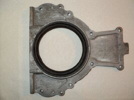
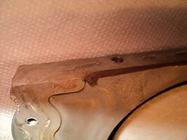
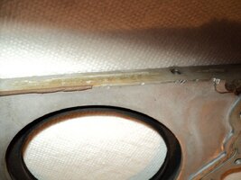
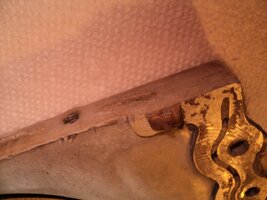
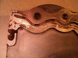
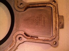
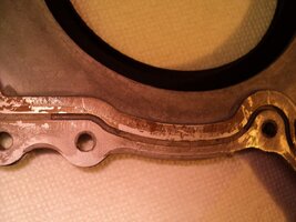
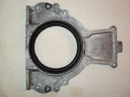
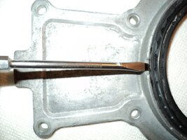
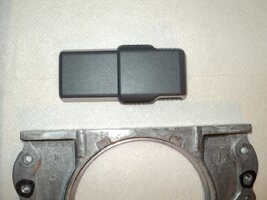
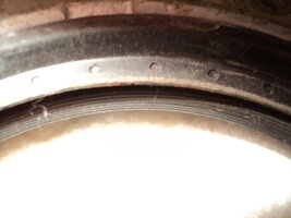
Recently, @Capote wisely changed out his Rear Engine Seal while sorting out the R&R of a Fractured Flex-Plate and you can see in his images that he decided to remove the entire unique end-plate as a whole unit. This same Rear Bolt-On Cover has Three Slots that can be addressed with a Flat Bladed Screw Driver and pried out...necessitating a careful re-install of Brand New Crankshaft Seal using a Block of Wood or... an expensive K&M Tool to slide the new seal over the end of the Crankshaft and ensure that the seal goes on and is not damaged or loses the dual sealing action when installed. Unless a Brand New Cover and Seal is being installed... the first option requires its own additional work to prepare the old cover for this New Seal. I am showing what his Rear Engine plate would look like here.

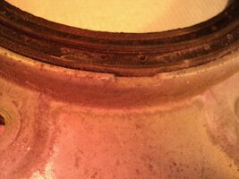
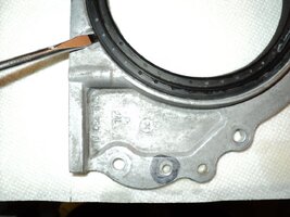
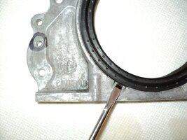
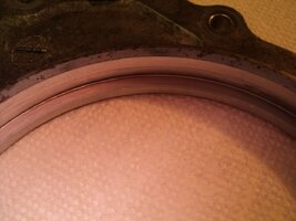
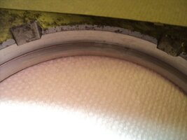
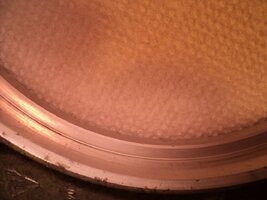
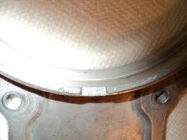
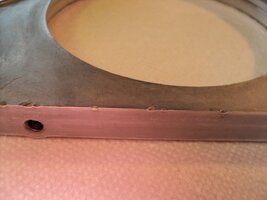
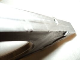
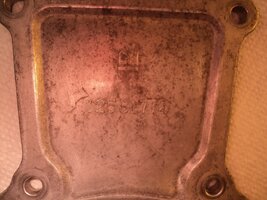
The attached photos illustrate how careful one must be when using a small knife to clean out all of the edges and grooves on the Machined Inner Face of the Aluminum Cover and this job is NOT a trivial matter. When you look at the First Few Images...you notice that they do NOT look all that bad, However...on closer inspection...the grooves are clogged and clotted with dried, desiccated, Rubbery Old Gray RTV and dirt all over the Flange Mating Surfaces in all Three Axis... as this Aluminum Plate also adds structural strength to the back of the engine. The other tool necessary to clean this plate up nicely is a Brand New Linoleum Razor Blade... that gets applied by being set Flush and Even with the Machined Flange Surfaces...and is DRAGGED BACKWARDS... to effectively clean all of these mating surfaces spotless and shiny... WITHOUT scraping off or damaging any of these metal surfaces. Don't be dismayed that the concavity inside of those grooves looks "corroded" or uneven... because what you are seeing there has been done "By Design" to maintain what they call a "Tooth" inside those Grooves to help the Aluminum Plate to adhere to OEM AC-Delco's very viscous RTV.

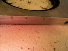
It follows that the Old RTV will be nested inside the Bolt Through Holes and in particular... this needs careful extraction by using the sharp pointed end of the Razor Blade to coax the sticky and very rubbery junk out of there. As usual... during your own Engine Autopsy...looking over each and every component for Defects or Damage is the order of the day. In the case of this Exemplar Rear Cover Plate... This is one I picked up for $10.00 on eBay...and if you look very closely at the images of the Lower Flange... you will see that the Scrap Yard worker could NOT get the plate loose from the engine and Crankcase-Oil Pan...so he stuck a Pry Tool of some kind in between the two flanges and Pried the Hell out of it to get it to come loose. As @Mooseman has instructed us on How to Remove the Crankcase Oil Pan.... by screwing Two Pan Bolts; One on either side at the Rear of the Crankcase-Oil Pan... This very same technique applies here (See the images showing the Black Magic Marker Circles to locate the Threaded Holes on the Rear Crankshaft Cover).

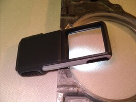
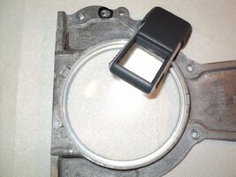
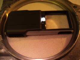
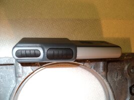
With the addition of the need to remove the Oil Pick up Tube from the Front Cover and Install the New Gerotor oil pump and Crankshaft Seal into the Front Cover.... These Cleaning Procedures apply there as well. The OEM GM RTV is the BEST High Temperature, High Endurance “Goo” to use... as the Manual describes how Thick of a Bead to lay down on the surfaces.... IINM.... The Working Time for this Special Stuff is 15 Minutes. I have Two Sets of Images to post at the required 10 Minute intervals...so more of them will follow. By the way... Walgreens sells a VERY Nifty and Slim Lighted Pocket Magnifier that is extremely handy for people with Presbyopia (If you are Over 40... You will know what THAT means) and for examining things quickly, up close and personal...without having to lug around anything like a separate Magnifying Glass and a Flash-Light while also trying to hold onto the parts being looked over (Images attached in the next entry below)
DSC07292.jpg DSC07296.jpg DSC07298.jpg DSC07299.jpg DSC07300.jpg DSC07301.jpg DSC07303.jpg DSC07304.jpg DSC07305.jpg DSC07306.jpg DSC07308.jpg DSC07310.jpg DSC07311.jpg DSC07313.jpg DSC07317.jpg DSC07319.jpg DSC07320.jpg DSC07323.jpg DSC07325.jpg DSC07328.jpg
 

Attachments

  • DSC07329.jpg
    DSC07329.jpg
    109.3 KB · Views: 0
  • DSC07330.jpg
    DSC07330.jpg
    102.7 KB · Views: 1
  • DSC07331.jpg
    DSC07331.jpg
    95.6 KB · Views: 1
  • DSC07332.jpg
    DSC07332.jpg
    79.6 KB · Views: 0
  • DSC07333.jpg
    DSC07333.jpg
    97.9 KB · Views: 1
Last edited:

mrrsm

Lifetime VIP Donor
Supporting Donor
Member
Oct 22, 2015
8,192
Tampa Bay Area
Here are the last of this group of images relating to The Clean Up and Prep of The Rear Engine Cover... Please take note of the damage done to the rear flange edges and surface that mates with the Crankcase by someone in haste to get the RC off ....without either knowing about, or being patient enough to use @Mooseman 's Idea:

DSC07334.jpg DSC07337.jpg DSC07338.jpg DSC07339.jpg DSC07340.jpg DSC07341.jpg DSC07342.jpg DSC07344.jpg DSC07345.jpg DSC07346.jpg DSC07347.jpg DSC07348.jpg DSC07349.jpg DSC07350.jpg
 

Mooseman

Moderator
Dec 4, 2011
25,996
Ottawa, ON
  • Like
Reactions: mrrsm

m.mcmillen

Original poster
Member
Apr 29, 2016
556
Wisconsin
I have done a bit of work on the engine this weekend but I will write about that later when I have more time.

I thought I would mention two things.

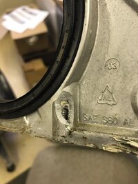
First, when you're removing your oil pan for whatever reason, be sure to get the two bolts that go into the bottom of the rear main seal housing. I had my pan off last year and I didn't see those two bolts. Notice in the picture that mine is broken. I was trying to get the pan off and it wouldn't move. Apparently, I tried a little too hard.
housing.JPG

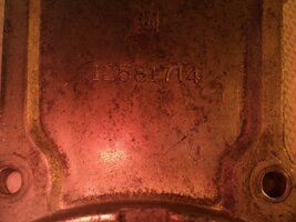
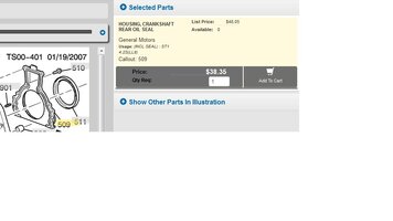
Second, I ordered the housing from the dealer for $38. It includes the seal. If you're changing the seal, it is worth it in my opinion to just buy the whole thing and not have to worry about getting that seal in just right.

The part number for the seal and housing together is 12581714
seal.jpg
 
Last edited:

m.mcmillen

Original poster
Member
Apr 29, 2016
556
Wisconsin
The engine is finally back together. I've been working on it most of the day today. I have it in and bolted to the transmission and the torque converter bolted up. Now it is time to put all the parts and pieces back on the engine.

I was able to prime the oil system. When I assembled the oil pump, I packed the pump with Lubriplate engine assembly lube. I cranked the engine with no spark plugs installed. My battery was kind of weak from sitting for 2+ months. I had to get out the jump pack. After about 10-15 seconds of cranking I started getting about 5 pounds of oil pressure. I cranked a bit more, maybe another 10 seconds or so, and I got a steady 30 pounds of oil pressure.

I'm hoping to fire it up tonight or tomorrow sometime. It depends on when I run out of steam.
 

mrrsm

Lifetime VIP Donor
Supporting Donor
Member
Oct 22, 2015
8,192
Tampa Bay Area
@m.mcmillen ... For the sake of your Readers, "The Legendary Mac" has proven that he is possessed of a level of Mechanical Knowledge and Experience that is Profound .... and this has given him the ability to tear this Atlas Engine down to its Atoms and then carefully re-construct it with confidence.

If any of you out there in "GMT Nationland" will follow in his footsteps... there are some things to do well before you "Put The Music" to it and Fire Up your Re-Built Engine. THIS is the time to Follow the Warnings of the Butterflies Inside your Stomach by Asking Yourself these Questions as your "Engine Break-In Engine Builder (15) Baker's Dozen:

(1) Did I Fill the Crankcase with Engine Break-In Oil and Additives?
(2) Did I Pre-Fill the Oil Filter before Screwing it on under the Engine Block?
(3) Did I Charge the Battery The Night Before The Big Day?
(4) Did I Fill the Radiator with Fresh 50/50 GM Approved Coolant?
(5) Did I secure a Reliable "Spotter" to be On Time on The Big Day?
(6) Do I Have a Basic Tool Set and Shop Rags on Hands to deal with any Leaks?
(7) Do I have enough Extra Coolant to Add to the Radiator & Keep it Topped Off?
(8) Do I have a Charged ABC Fire Extinguisher available & off to one side?
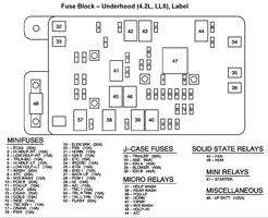
(9) Did I R&R Pull the IGN (Ignition Relay #22) to Oil Prime the Engine?
(10) Did I pour in some Chevron Techron into the Gas Tank to Prepare the Fuel?
(11) Did I Remove the Wheel Chocks & any Safety Equipment around the Vehicle?
(12) Have I Checked and advised Family, Friends, Neighbors NOT to stand nearby?
(14) Did I say that One Last, Fervent Prayer to the God of the Mechanical Universe? (Yeah... I skipped one # I'm superstitious about certain numbers)
(15) Do I have the Best Pizza Shop on my Speed Dial?

TRAILBLAZERFUSEPANEL.gif

When at last "The Moment of Truth" arrives... have your Spotter available to watch closely Before, During and After the 30 Minute Period of The First Engine Start and Break In Period, The Spotter must be very responsible while acting as your Eyes and Ears scouring the Engine from Top to Bottom while you watch the Critical Engine Gauges for nominal Engine Oil Pressure and Coolant Temperature. After the engine comes up to the Proper Operating Temperature... Try to vary your RPM VERY GRADUALLY between idle and 1,500 RPM... and avoid doing any "Snap Throttle" actions to "surprise" this engine.

The last thing you want to do is force Brand New Rings on Brand New Pistons inside "unseasoned" Cylinders to be Over-Stressed before they have even had the chance to get introduced to one another. IF ANYTHING UNUSUAL HAPPENS... SHUT OFF THE ENGINE AND OBSERVE WHAT IS HAPPENING UNDER THE HOOD. Listen... Look and STOP the Motor if your Oil Pressure Gauge DROPS below 12 PSI or Goes to ZERO. This phenomena can happen if the Pre-Set Spring in the Constant 65 PSI Oil Pressure Valve inside the Oil Pump should jamb.... and also if you used Molybdenum Di-Sulphide or Very Thick Engine Assembly Lube in such a quantity as to CLOG THE OIL FILTER VERY QUICKLY. ....................DO NOT PANIC!....................

Just Install a Brand New Oil Filter after Pre-Filling it to the Brim with Engine Break-In Oil, go through the Same Start-Up Procedures as before. You should be "Out of the Woods" and the problems encountered by Hansel and Gretel after the 30 Minute Break-In period. Check all Fluid Levels... Then Do that Famous Victory Dance that will make your Neighbors think you have Lost Your Mind. It will be time to relax and Eat Some Pizza (leave the Beer-Wine for later). When you feel up to it... take the vehicle for a very leisurely drive for around 10 Minutes through the Neighborhood... listening for anything unusual and once back home in your driveway... shut down the engine and slip a Large and Long Piece of Cardboard underneath the areas of the Engine AND the Transmission. Check on this cardboard after 15-30 minutes for any unusual leaks.

Note any secondary Codes or Warnings collected on your Scanner that can be handled later on and after a requisite GM Dealership CASE Re-Learn for the Crankshaft and Transmission gear timing issues and a PCM Software Update ...you should be Good To Go! Drive this vehicle to the First 500 Miles NORMALLY WITH NO RADICAL STRESSES ON THE MOTOR!. Then CHANGE THE OIL AND OIL FILTER USING THE SAME ENGINE BREAK-IN OIL AND ADDITIVES. Once again only... Do this very same procedure at 1,500 Miles. Finally... at 3,000 Miles, switch to Mobil1 and K&N Oil Filters ...and after that every 3,000 Miles for "As Long as Grass is Green... and Skies are Blue...".

"Happy Motoring...!"
 
Last edited:

m.mcmillen

Original poster
Member
Apr 29, 2016
556
Wisconsin
Here are the steps that I use when I prime an engine:

1. Set the engine on the mounts.
2. Bolt the engine and transmission together.
3. Bolt the torque converter to the flex plate.
4. Pre-fill an oil filter with oil and fill the engine to the specified oil level.
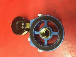
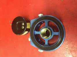
5. Install a manual oil pressure gauge. I used a sandwich adapter with a pressure gauge installed into the adapter. The adapter gets screwed onto the oil filter housing and then screw the oil filter onto the adapter.
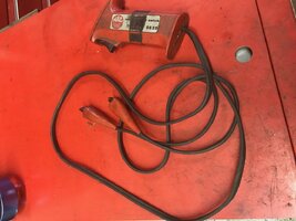
6. I have a switch on about 3 feet of two wire cord that I use to engage the starter. One wire gets clipped to the positive lead on the starter and the other lead goes on the signal wire. Crank the engine with the spark plugs removed in short bursts. Once you get a satisfactory amount of oil pressure, you can move on with the installation of the engine.

There are a few reasons that I do it this way. First, if you try to prime it and for some reason something happens and you have to take the engine back out, you've done a minimal amount or work so you don't have a lot of things to undo.

Second, one time, while I was installing a newly rebuilt engine, I plugged in all of the sensors and went to prime the engine and forgot to install one ground wire. The starter clicked once and then nothing would happen. I noticed the wire and went on my way. Once I got the engine running the check engine light was on and the codes all related to circuit problems with the sensors I had installed at the time I was priming the engine. Long story short, I fried the PCM.

Third, I like to be close by the engine and see it turning and listen for anything strange going on. Plus, the hose on my oil pressure gauge isn't long enough to reach anywhere that I can see it from inside.

On break in oil: I don't really think that there is a need for it anymore. I just make sure to use a non-synthetic oil starting out. I change the oil at 50 miles and then 1500 miles. Break in oils, in my opinion, are more for engines that have flat tappet lifters (old engines).

I have been driving my Trailblazer around the last couple of days and it is quieter then I can remember it ever being. I haven't noticed any oil leaks or anything. It did stink under the hood for a while but I think it was my new exhaust manifold. It was coated with some sort of grease, probably to keep it from getting a coat of rust on it while it was sitting in the box.

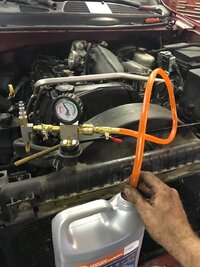
When putting coolant in, I have this handy tool that pulls a vacuum on the system and then you open a valve with a hose on it and the coolant gets sucked into the system. This helps to not get air pockets in the cooling system.

IMG_3663.JPG

I will do the CASE relearn after a while. I don't think that revving the engine to 4,000 right now would be a good idea right now. This does not have to be done at a dealership. You can go to most any shop that has a decent scan tool and do this for much cheaper then going to the dealer. My Snap On scanner will do it and I have done it with one from Auto Ingenuity (https://www.autoenginuity.com/wordpress/products/scantool/) I believe that Autel scanners will do it as well.
 
  • Like
Reactions: mrrsm

m.mcmillen

Original poster
Member
Apr 29, 2016
556
Wisconsin
Yesterday I was able to charge my A/C up and give everything a good washing. It was pretty dusty from sitting in the shop for nearly 2 months.

I'm hoping to go put some miles on the engine today and do an oil change. I've only got about 20 miles on it so far. The engine runs great so far and is much, much quieter.
 

mrrsm

Lifetime VIP Donor
Supporting Donor
Member
Oct 22, 2015
8,192
Tampa Bay Area
****Sighs of Relief and Satisfaction Came From The Crowd****

Say Brother... Any chance you could lay out your unique Starter Switch-N-Wires and that "Sandwich Oil Pressure Gauge" Tools and drop a few images of them here for us to see? Thanks!
 

m.mcmillen

Original poster
Member
Apr 29, 2016
556
Wisconsin
Here you go.
I bought the adapter on amazon https://www.amazon.com/gp/product/B00CS56PE0/?tag=gmtnation-20

The starter switch was made by Mac tools. It came with a bunch of tools that I bought from my co-worker that retired a few years ago (80 years old). I suppose you could buy one at most any parts store.

IMG_3698.JPG IMG_3699.JPG IMG_3700.JPG

I will be out all next week driving a bus for work and I will have a bit of down time while I'm waiting around for people. I will try and put together a parts list and any special tools that were needed for the rebuild.
 

Attachments

  • IMG_3699.JPG
    IMG_3699.JPG
    87.1 KB · Views: 7

mrrsm

Lifetime VIP Donor
Supporting Donor
Member
Oct 22, 2015
8,192
Tampa Bay Area

m.mcmillen

Original poster
Member
Apr 29, 2016
556
Wisconsin
I haven't had a chance to do much writing lately. I've been out of town a lot with work and this coming week looks to be pretty busy too. I have to go pick up a radiator for our MCI bus (2 1/2 hours one way), change the radiator, drive the bus to Michigan to pick up some people, work on a cylinder head job in a Chevy Uplander, and then drive the bus back to Michigan to drop some people off.

I've hardly had a chance to even drive my TB. I've put around 300 miles on it so far. I did have a chance to do my 100 mile oil change (at 150 miles) last week. Today, I had a bit of spare time so I gave it a much needed wash.

I don't see any oil leaks so that's good and everything seems to be running pretty good. My MPG are down a bit but I'm sure there's a bit more friction in there with the new rings. I expect it to come up once I get some more miles on it.
IMG_1273.jpeg
 

mrrsm

Lifetime VIP Donor
Supporting Donor
Member
Oct 22, 2015
8,192
Tampa Bay Area
@m.mcmillen ... I could use your insights into the fact that I accidentally moved the Pre-Set Rotating Assembly when I had my Donor Motor flipped 180 Degrees for cleaning and prepping. Later, I found a Small, Narrow Patch of Rust exposed along the upper rim of the #1 Cylinder that I will have to dress out prior to installing the New Engine Head and this prompts Two Questions:

(1) When you replaced the Pistons and Rings in your "Legendary Mac-Re-Manned Engine"... Did you use OEM Rings and were they Cast Iron or Moly-D for the Top Compression Ring? I just want to make sure no real damage from the minor rust has happened to that Top Ring and whether I will have to treat the rings to a heavy dose of Kroil in order to dissolve any hidden "Ring Rust".

(2) When you installed your Crankshaft "from scratch"... exactly what technique did you follow to ensure that the #1 Piston was at TDC and NOT on the Exhaust Stroke? I'm assuming you achieved this by simply positioning the #1 Piston at TDC with the Crankshaft Alignment Pin for the Gerotor Oil Pump Sprocket set exactly at the 12 O'Clock High... but I'd like the benefit of hearing from you whether or not this is the correct way to get it set up... or am I missing something here?
 

m.mcmillen

Original poster
Member
Apr 29, 2016
556
Wisconsin
Sorry for the late response. I've been pretty busy with work this week.

I didn't use OEM rings. I used Sealed Power rings. Part number E969K. They are moly rings.

As far as TDC is concerned, there isn't any compression or exhaust stroke with no head or cam installed. TDC is TDC.

My oil pump didn't have any type of pin in it. The end of the crankshaft was more like a splined end. I assembled the pump in the front cover and just eyeballed the alignment of the pump. To make sure everything went together correctly I installed the front cover with no front seal installed and no sealant on it. I believe that I had to turn the crankshaft a bit to get the pump lined up. Since the chain was already installed it didn't matter if I turned the crankshaft.

Once everything was lined up, I pulled the front cover back off. The pump stayed in the exact position I had it in because I had a fair amount of grease in it to help with priming the system. I then installed the front seal and used the ACDELCO sealer on the cover and bolted it on. I don't remember right off hand what the size of the bolts are for the front cover but I used two really long bolts with the heads cut off for alignment pins instead of buying the special GM recommended tool.
 

mrrsm

Lifetime VIP Donor
Supporting Donor
Member
Oct 22, 2015
8,192
Tampa Bay Area
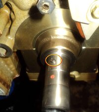
Uh Oh... Sorry...I think I mislead your thinking a bit... The "PIN" I was addressing is actually the Pin that the Grooved Slotted inside of the Crankshaft Gerotor Pump Cog actually slides over and the Pin grabs the inner space in order to impart the rotation force and grip the Crankshaft needs in order to turn it,,, and the entire Timing Chain Set Assembly as well.

GEROTOROILPUMPSPROCKETPIN.jpeg
My question was... did you have your Crankshaft in the position you can see in my image...or was it in some other position when you installed the Crankshaft from scratch? It does seem possible to get this 180 Degrees out...and that was my concern. ;>)
 

m.mcmillen

Original poster
Member
Apr 29, 2016
556
Wisconsin
Oh, oops I forgot about that part. But still, with no chain installed, it doesn't matter. If you have a piston at TDC and then turn the crank 180 degrees then you will be at BDC. Turn it another 180 and you'll be at TDC again.

Or maybe I'm still not following you...
 
  • Like
Reactions: mrrsm

m.mcmillen

Original poster
Member
Apr 29, 2016
556
Wisconsin
Here is the list of parts that I bought from Rockauto. I bought several things from the dealer also. I will add those later when I have time to dig out the receipts.


CLOYES 90195S (9-0195S) Timing Set $ 154.79

FEL-PRO HS26214PT Cylinder Head Gasket / Head Gasket Set $ 119.79

FEL-PRO CS26213 Conversion (Lower) Gasket Set $ 33.79

FEL-PRO ES71334 Cylinder Head Bolts $ 49.79

MAHLE/CLEVITE MS2224AL Crankshaft Main Bearing (whole set)
Size: Standard $ 130.79

MAHLE/CLEVITE CB1882A6 (CB-1882A(6)) Connecting Rod Bearing
Size: Standard $ 43.99

SEALED POWER H889CP Piston (whole set)
Size: Standard $ 293.34

SEALED POWER E969K (E-969K) Piston Ring (whole set)
Size: Standard $93.79
 

Bondo07

Member
Mar 5, 2017
57
Hutchinson, MN
Hi mcmillan, you've been commenting on my post on facebook, and linked me here. Was wondering if you would mind me posting up all my rebuild pics on here since apparently I'm one of very few people to attempt this.
 

Mooseman

Moderator
Dec 4, 2011
25,996
Ottawa, ON
I would recommend that you start your own thread just to keep things neat and tidy and post a link to it here.
 

Forum Statistics

Threads
23,664
Posts
641,768
Members
19,092
Latest member
jarmwire

Members Online

No members online now.