NEED HELP 05 Trailblazer Fuel Gauge Problem. Bad PCM?

TJBaker57

Member
Aug 16, 2015
2,900
Colorado
Well I will add this.

We already know the gauge is positioned by the cluster electronics driving the stepper motor in response to messages from the PCM which reads the tank level sender. The PCM sends out a nominal 5 volt signal and reads the voltage remaining after the sender has created a drop by applying a resistance across the nominal 5 volt signal and a low reference. Where was I going??? Oh yes! The messages from the PCM take the form "A8 83 10 12 xx" where xx is a value between 0x00 and 0xFF. On my 2002s 0x00 nominally represents empty and 0xFF nominally represents full. I would imagine the voltage from the sensor is not linear due to the geometry of the swinging float arm but for the purpose of this post that doesn't matter as I am not addressing that signal.

Specifically, on both my 2002 TrailBlazer and my 2003 benchtop testbed the low fuel level light comes on when the level as reported by the PCM to the cluster hits 0x10. The low level light turns off when the level as reported by the PCM rises and hits 0x1C.

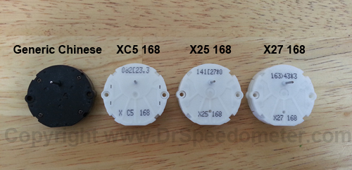
My 2002 gauge points of reference in hex:

E = 0x0C
1/8 = 0x22
1/4 = 0x36
1/2 = 0x77
3/4 = 0xB7
F = 0xD6

Does this help?? I doubt it very much.
 
  • Like
Reactions: Mooseman

budwich

Member
Jun 16, 2013
2,050
kanata
It probably does help a bit. The OP needs to correlate his PCM reading to the warning / "E". That will likely indicate if there is some issue. But back to "design intent".... when is "E" really empty. As you indicate, the system is not intented to be an accurate measure of fuel level. Its an indicator.
Further to this, is when is "full" really full. I have monitored my fuel level (for fun) at times. A full of 100% can give me 50-100km (depending on how full it was filled) before it moves off the 100% and the gage moves back towards F as opposed to being past it.

I guess one question for tjbaker57 is: Have you ever taken a fuel sensor and moved it thru its "arm swing" to simulate fuel level and read the output to correlate the swing "percentage" to value. ie. does 00 & FF really corresponding to maximum swing - top and bottom of the "fuel tank"?
 
Last edited:
  • Like
Reactions: Mooseman

Zmoney

Original poster
Member
Jun 4, 2021
30
US
You're right. It is useful information.

Again, mine is receiving a signal that says full but immediately starts to drop down without any hang time above the F mark.

Im reading E at around 1/5 tank left or better.

It has to be a corrosion issue or something leading to extra resistance between the PCM and the cluster.

I think.

Oh. Ill add in one more little bit of info. This last time when my mechanic confirmed the pcm reading was higher than what the cluster displayed, I took a couple more full trips and now the cluster is showing about 1/8 tank after multiple restarts.

Thank you everyone!!!

I'll keep digging.
 

budwich

Member
Jun 16, 2013
2,050
kanata
It has to be a corrosion issue or something leading to extra resistance between the PCM and the cluster.
the interface is digital so it is unlikely to have any impact although potential a "bus error" might be a result but not likely a display "difference".
 

mrrsm

Lifetime VIP Donor
Supporting Donor
Member
Oct 22, 2015
7,737
Tampa Bay Area
@MAY03LT produced an interesting On Topic Video that is worth watching by anyone else facing this problem and yet uninitiated with its mechanical operation, appearance, testing and repair.

The Video also serves as an opportunity for the OP to make the comparison of the close-up appearance of the Fuel Float Level Sending Unit Drew is demonstrating in great detail "On The Bench" ...and thus it provides an opportunity for checking the following:

(1) Does the OEM Float Sending Unit he demonstrates On Camera look identical in length, appearance and operational positions to the one you changed out on your New Delphi Fuel Pump?

(2) Was the Replacement Fuel Pump Level Sending Unit the OP installed an identical OEM Part... or was an After-Market Unit swapped in its place?

(3) If not... is there also another Fuel Pump Level Sending Unit available that is meant for installation on either Larger or Smaller GM Fuel Tanks that could have been re-stocked at the Parts Store and unknowingly installed into the Fuel Tank?

(4) Is the OP the original Owner of the SUV to confirm that the in-dwelling Fuel Tank has the Stock Item installed from the GM Factory?


Zmoney

Original poster
Member
Jun 4, 2021
30
US
@MAY03LT produced an interesting On Topic Video that is worth watching by anyone else facing this problem and yet uninitiated with its mechanical operation, appearance, testing and repair.

The Video also serves as an opportunity for the OP to make the comparison of the close-up appearance of the Fuel Float Level Sending Unit Drew is demonstrating in great detail "On The Bench" ...and thus it provides an opportunity for checking the following:

(1) Does the OEM Float Sending Unit he demonstrates On Camera look identical in length, appearance and operational positions to the one you changed out on your New Delphi Fuel Pump?

(2) Was the Replacement Fuel Pump Level Sending Unit the OP installed an identical OEM Part... or was an After-Market Unit swapped in its place?

(3) If not... is there also another Fuel Pump Level Sending Unit available that is meant for installation on either Larger or Smaller GM Fuel Tanks that could have been re-stocked at the Parts Store and unknowingly installed into the Fuel Tank?

(4) Is the OP the original Owner of the SUV to confirm that the in-dwelling Fuel Tank has the Stock Item installed from the GM Factory?

I am the second owner.

Original Sending Unit was swapped out by my mechanic for a Delphi pump from a donor vehicle.

The first 'version' of this issue manifested when I thought that I had a bad unit at that time because my cluster at full would simply display between 3/4 and 7/8 of a tank as soon as I filled up.

I actually referenced that video when I made the first swap myself (from mechanic's replacement to my own install) and thought I had a dead spot.

At this point I had thought the sending unit itself was the problem, so I swapped it out for a brand new delphi unit. It worked, but presented the issue of rapidly dropping from full to 3/4 within 25-50 miles after fillup, then dropping 'normally' until it showed empty with typically 5-6 gallons still left in the tank.

Another poster here informed me that I was using a pump model specifically meant for an EXT tank when I posted the model. So I then returned that and got another brand new Delphi sender of the appropriate model. (from a completely different vendor, as the one who sold me the LWB-appropriate model didn't have it listed properly and made me give them hell and fury to get it refunded)


All of the above but the original (that my mechanic replaced) had this issue (the stock unit was swapped because fuel pressure was low... pump was burnt out)

The one he first installed did not initially have any kind of issue like this. The truck sat for about a year then this started happening.

I'll review the video again and get ready to do some more testing. I really just don't believe that the sender itself is the issue after three different name-brand units (two factory sealed) are all doing it.

I know there are a lot of cheap-o chinese senders on the market. I didn't buy them for fear they'd be garbage.

Thank you for reminding me of the vid though. :biggrin:
 
  • Like
Reactions: mrrsm

mrrsm

Lifetime VIP Donor
Supporting Donor
Member
Oct 22, 2015
7,737
Tampa Bay Area
As with most of @MAY03LT 's Videos... he saves "The Jam in The Jelly Roll" for Last... so watching them all the way to the end can often glean some very cool Extra Insights. :>)

One other Clue from your response dwells on the possibility of having Wire Damage from Rodents (Deer Mice in particular) that seem to find their way into the GMT360 SUVs after they have been sitting for long periods and manage their endless incisor teeth growing via gnawing on Plastic Connectors and Wire Bundles, too. If you see signs like these under the hood as mentioned in the linked Thread...Performing Circuit Testing-Proofing and some Wire Bundle Inspections would be a good idea:

Check out Post #17 for a suggestion about tightening the Fasteners holding the Fuse Block to the Wiring Harnesses


If you discover any Wiring Damage... consider getting THIS Automotive Grade Wire Bundle that will mostly match the OEM Colors and Qualities of the indigenous wire and ensure no failures after they pieces get Soldered and Heat Shrink Insulated back together. Top off the Job with a wipe down using some Peppermint Oil on the outer insulation and then pack some Cotton Balls soaked in that fragrant oil into the corners of the Underhood areas to discourage the "Return of The Critters":


Attachments

  • 9400b2444ad16911142a7c062a997e8d.jpg
    9400b2444ad16911142a7c062a997e8d.jpg
    38.2 KB · Views: 4
  • rodent-damage-repairs.jpg
    rodent-damage-repairs.jpg
    48.8 KB · Views: 2
  • MAF Connector 1 (Initial view) small.png
    MAF Connector 1 (Initial view) small.png
    501.6 KB · Views: 2
Last edited:

TJBaker57

Member
Aug 16, 2015
2,900
Colorado
Non-linearity more easily seen here for those not fluent in hexadecimal. The accuracy 'seems' to be center-weighted. Were I the designer I would have increased accuracy near Empty where it counts!

Screenshot_20210826-100717.png
 
  • Like
Reactions: budwich

Mooseman

Moderator
Dec 4, 2011
25,350
Ottawa, ON
I have found in all my trucks (see the list in my sig) are/were like this. They would drop quicker to 3/4 and then slow down, then speed up again, although not as much, as the initial 1/4. I think the reason is twofold.

One, the shape of the top of the tank makes it so that first quarter tank is smaller than the rest of the tank, which is flat.

bfbebf20-2697-4cdf-83bb-3d392adde01d.JPG


Two, the arc of the float arm would make it slow down from 3/4 to 1/4, which would be the longest part of the arc. This would also compound the first 1/4 drop and would also quicken it a bit at the last 1/4.

So the gauge readings are not linear.
 
  • Like
Reactions: budwich

TJBaker57

Member
Aug 16, 2015
2,900
Colorado
I have found in all my trucks (see the list in my sig) are/were like this. They would drop quicker to 3/4 and then slow down, then speed up again, although not as much, as the initial 1/4. I think the reason is twofold.

One, the shape of the top of the tank makes it so that first quarter tank is smaller than the rest of the tank, which is flat.

bfbebf20-2697-4cdf-83bb-3d392adde01d.JPG


Two, the arc of the float arm would make it slow down from 3/4 to 1/4, which would be the longest part of the arc. This would also compound the first 1/4 drop and would also quicken it a bit at the last 1/4.

So the gauge readings are not linear.

Easy to see why the sending unit data would be non linear. I would think if they wanted to they could overcome this in PCM software.

However, the data I posted is not from then sending unit at all. It is between the PCM and the gauge. And in reality the particular data I posted was from a session between my phone and the gauge/cluster. I just kept moving the gauge a little at a time nudging it to the major markings. Seems odd that would be non-linear.
 

budwich

Member
Jun 16, 2013
2,050
kanata
ah, the wonders of a "stepper motor" (and GM "algorithms")... :smile: I wonder how "responsive" they are to actual values meaning any "D to A", what is the resulting "step" in general.... ie. how many "hex" results in some observable change in the gage? and then how many "hex" comes from a change in sensor arm resistance? Anyway, I am thinking that this "problem" is more "design intent" than any fault / failure at this point.

further, just checked my gage. Its showing a half a tick about 1/4 tank while the PCM (torque calc) indicates 32%. This is about a 20% "difference".... if that "difference" is "maintained", on a 22 gal tank, that would be about 4-5 gallons along the way. Again, what's "empty" and "full" in "real terms".
 
Last edited:
  • Like
Reactions: TJBaker57

TJBaker57

Member
Aug 16, 2015
2,900
Colorado
Again, what's "empty" and "full" in "real terms".

Empty = hoofing it down the highway!! :wink:

ie. how many "hex" results in some observable change in the gage? and then how many "hex" comes from a change in sensor arm resistance?

By coincidence (or maybe not) I was recently fiddling with that sort of thing at the bench. Replacing the sender with a potentiometer and observing the changes in the value of the fuel level PID while also reading the voltage at the PCM. I didn't see the pid change as frequently as the serial data from PCM to the cluster at least suggesting the PID is filtered. Anyway, my potentiometer was not adequate to the task so I have ordered a few 10 turn linear wirewound units that should be more useful to me in these endeavors. My purpose in the testing is to see about tuning up the PID equation if possible. Normally I attempt to write an equation that reproduces what the Tech 2 would read out for the value in question.
 

budwich

Member
Jun 16, 2013
2,050
kanata
commendable... but as you mention and as expected, there is "filtering" on the output of the PCM because you don't want the gage to be bouncing around as you bounce down the highway.

In my past "conversation" with GM, they were unwilling to identify what level the warning was at and at the time, the "birth" of torque was just getting started and I didn't pursue this any further. But I am going to let mine run til the warning pops (on the DIC) and see what the level correlates to in terms of "E" posiition and % percentage as output by torque (assuming the equation / conversion is correct). Just for my own peace of mind.... I haven't seen the warning in years.

Update: 1/8 gage indication with 26% pcm "pid" output.
 
Last edited:
  • Like
Reactions: christo829

mrrsm

Lifetime VIP Donor
Supporting Donor
Member
Oct 22, 2015
7,737
Tampa Bay Area

Attachments

  • SB-10041526-6493.pdf
    53.4 KB · Views: 2

JayArr

Member
Sep 24, 2018
504
Mission BC Canada
I'd be looking at the stepper motor. You may have two clusters with bad stepper motors.

They are cheap as hell and have no feedback. The cluster calibrates them by pushing them CCW as far as they will go on startup and considering that as "zero". We've all seen how the dials sweep back and forth on startup, this is why. Each "step" in a stepper motors actuation can be as little as 1 degree so to get the dial to display half a tank the cluster may have to send 30 "fwd" commands to the motor to get it to move 30 degrees from home position. If any of those commands fail to move the dial forward your calibration is lost, not just for now but until you turn the car off and restart it.

If a motor fails to move on fwd commands but succeeds on RVR commands the dial will fall down below the correct value. This could be why it starts off reading full and then drifts down below where it should be.

Remember that the command given by the PCM is not in absolute control, it tells the cluster how far from "zero" the dial should be but with no feedback the cluster doesn't know if the dial is correct or not. It knows that it sent it the correct commands but it doesn't know if the stepper executed any of them.

The steppers are all the same for temp, oil, batt, fuel, speedo and tach. This makes troubleshooting a little easier. take the cluster apart and swap the fuel stepper with one of the gauges that works. I would pick Oil pressure since it's a stepper that probably moves the least and wears out last.

If your fuel guage now works but your oil pressure is erratic you've solved the mystery. These motors are only about $4 on eBay so order a bunch. Search for X27-168
 
  • Like
Reactions: Mektek and mrrsm

mrrsm

Lifetime VIP Donor
Supporting Donor
Member
Oct 22, 2015
7,737
Tampa Bay Area

TJBaker57

Member
Aug 16, 2015
2,900
Colorado
Remember that the command given by the PCM is not in absolute control, it tells the cluster how far from "zero" the dial should be but with no feedback the cluster doesn't know if the dial is correct or not. It knows that it sent it the correct commands but it doesn't know if the stepper executed any of them.


With an obd2 dongle and the Torque Pro app plus a little guidance from yours truly you can see the message from the PCM to the cluster and thus can know if the gauge is displaying what it was told to. Without having to take anything apart.

Just sayin'
 
  • Like
Reactions: Mektek

Zmoney

Original poster
Member
Jun 4, 2021
30
US
With an obd2 dongle and the Torque Pro app plus a little guidance from yours truly you can see the message from the PCM to the cluster and thus can know if the gauge is displaying what it was told to. Without having to take anything apart.

Just sayin'
Ok but Im doing something wrong then because I made the change to the custom PID and dont get any data.
 

Zmoney

Original poster
Member
Jun 4, 2021
30
US
If you are doing the stepper motors might as well upgrade to new LEDs it looks a lot betterView attachment 101588
Any idea if the text display backlight can be changed? I usually have to tap on mine duting the day to get it to go bright, so I know something is loose in there. Also, if you have a link to the leds, yep I'd do it. My lower dash components have been hanging out in my back seat for months now. May as well.
 

Zmoney

Original poster
Member
Jun 4, 2021
30
US
I'd be looking at the stepper motor. You may have two clusters with bad stepper motors.

They are cheap as hell and have no feedback. The cluster calibrates them by pushing them CCW as far as they will go on startup and considering that as "zero". We've all seen how the dials sweep back and forth on startup, this is why. Each "step" in a stepper motors actuation can be as little as 1 degree so to get the dial to display half a tank the cluster may have to send 30 "fwd" commands to the motor to get it to move 30 degrees from home position. If any of those commands fail to move the dial forward your calibration is lost, not just for now but until you turn the car off and restart it.

If a motor fails to move on fwd commands but succeeds on RVR commands the dial will fall down below the correct value. This could be why it starts off reading full and then drifts down below where it should be.

Remember that the command given by the PCM is not in absolute control, it tells the cluster how far from "zero" the dial should be but with no feedback the cluster doesn't know if the dial is correct or not. It knows that it sent it the correct commands but it doesn't know if the stepper executed any of them.

The steppers are all the same for temp, oil, batt, fuel, speedo and tach. This makes troubleshooting a little easier. take the cluster apart and swap the fuel stepper with one of the gauges that works. I would pick Oil pressure since it's a stepper that probably moves the least and wears out last.

If your fuel guage now works but your oil pressure is erratic you've solved the mystery. These motors are only about $4 on eBay so order a bunch. Search for X27-1
I have found in all my trucks (see the list in my sig) are/were like this. They would drop quicker to 3/4 and then slow down, then speed up again, although not as much, as the initial 1/4. I think the reason is twofold.

One, the shape of the top of the tank makes it so that first quarter tank is smaller than the rest of the tank, which is flat.

bfbebf20-2697-4cdf-83bb-3d392adde01d.JPG


Two, the arc of the float arm would make it slow down from 3/4 to 1/4, which would be the longest part of the arc. This would also compound the first 1/4 drop and would also quicken it a bit at the last 1/4.

So the gauge readings are not linear.
My sender is within the rear 1/3 area
I'd be looking at the stepper motor. You may have two clusters with bad stepper motors.

They are cheap as hell and have no feedback. The cluster calibrates them by pushing them CCW as far as they will go on startup and considering that as "zero". We've all seen how the dials sweep back and forth on startup, this is why. Each "step" in a stepper motors actuation can be as little as 1 degree so to get the dial to display half a tank the cluster may have to send 30 "fwd" commands to the motor to get it to move 30 degrees from home position. If any of those commands fail to move the dial forward your calibration is lost, not just for now but until you turn the car off and restart it.

If a motor fails to move on fwd commands but succeeds on RVR commands the dial will fall down below the correct value. This could be why it starts off reading full and then drifts down below where it should be.

Remember that the command given by the PCM is not in absolute control, it tells the cluster how far from "zero" the dial should be but with no feedback the cluster doesn't know if the dial is correct or not. It knows that it sent it the correct commands but it doesn't know if the stepper executed any of them.

The steppers are all the same for temp, oil, batt, fuel, speedo and tach. This makes troubleshooting a little easier. take the cluster apart and swap the fuel stepper with one of the gauges that works. I would pick Oil pressure since it's a stepper that probably moves the least and wears out last.

If your fuel guage now works but your oil pressure is erratic you've solved the mystery. These motors are only about $4 on eBay so order a bunch. Search for X27-168
Thats very sensible. Ill out it at the top of my to do list.

Im wondering if there are signals sent to the stepper to reverse actuation as well. Im sure there is something built in to the calculation to compensate for liquid movement in the tank, otherwise your fuel level readout would fluctuate like your spedometer, but I wonder how often these minor calculations for needle position are sent.

Maybe the pcm sends two degrees down, then corrects one degree back up later and the stepper doesnt comply?

I drove deep past the E light this last time just to see what would happen and after a couple of restarts I went back above E for a couple more shirt trips. It just usually hits low fuel warning with 5-6 gallons in it (a quarter tank or more for me) and I dont wanna rely on the odo for fear of burning the pump or getting stranded if my estimates are somehow off.

Also with gas prices what they are, its purely psychological that I want to see 3xx miles out of my tank instead of running to the gas man way earlier. 😂
 
Last edited:

budwich

Member
Jun 16, 2013
2,050
kanata
Ok but Im doing something wrong then because I made the change to the custom PID and dont get any data.
you need to post a screen shot of the PID equation that you currently have put in the "manage pids" section. That will tell tjbaker57 exactly what's up and get at least the PCM reading out for you.
 
  • Like
Reactions: TJBaker57

Zmoney

Original poster
Member
Jun 4, 2021
30
US
Here we are
 

Attachments

  • Screenshot_20210829-094140.png
    Screenshot_20210829-094140.png
    891.8 KB · Views: 8
  • Screenshot_20210829-094218.png
    Screenshot_20210829-094218.png
    886.2 KB · Views: 8

TJBaker57

Member
Aug 16, 2015
2,900
Colorado
Here we are


What the F ??

You have too many " F" in there!

Mode and PID should read "22002F01"


And while we are discussing this. The above PID gets you what the PCM has in memory for the fuel level as seen by the GM Tech 2 scantool.

There is another different thing I can see on my 2002 and this should work for yours. I can request the PCM to send to the scantool the same message it sends to the cluster.

Screenshot_20210829-085255.pngScreenshot_20210829-085313.png


Followers of some of my other threads on SAE J1850 VPW communications might notice this message is a functionally addressed message to the primary ID of the Fuel System and a secondary ID of fuel level.
 
  • Like
Reactions: azswiss and budwich

Blckshdw

Moderator
Nov 20, 2011
10,685
Tampa Bay Area, FL
Any idea if the text display backlight can be changed? I usually have to tap on mine duting the day to get it to go bright, so I know something is loose in there. Also, if you have a link to the leds, yep I'd do it. My lower dash components have been hanging out in my back seat for months now. May as well.

The gear indicator and DIC (if you have one) colors can't be changed directly. You may be able to touch up the solder joints on yours to resolve the need to tap it though. When I swapped my lights out for blue LEDs ,these are the style I prefer, as the resistors are already built in. :twocents:
 

budwich

Member
Jun 16, 2013
2,050
kanata
WT "F"... :smile:
its appears that with info, at least the data should now be obvious. I suspect that actual gage display isn't going to change in terms of E as I suspect the "degree of E" might be "design intent".
 

Zmoney

Original poster
Member
Jun 4, 2021
30
US
Well my fuel light used to come on with about 2 gallons left in the tank. Now it comes on when there's six.

Shrugs
 

JayArr

Member
Sep 24, 2018
504
Mission BC Canada
With an obd2 dongle and the Torque Pro app plus a little guidance from yours truly you can see the message from the PCM to the cluster and thus can know if the gauge is displaying what it was told to. Without having to take anything apart.

It's close but it stops at telling you only that the command was sent to the cluster, it doesn't confirm that the cluster received it or if the problem is with the cluster CPU, the stepper motor driver transistors or the stepper motor.

Im wondering if there are signals sent to the stepper to reverse actuation as well.

Of course, a stepper motor must be commanded in both directions. There is no spring or recoil. It also is "held" in position when not being commanded in either direction so the needle shouldn't move in response to inertia created by driving conditions.

Maybe the pcm sends two degrees down, then corrects one degree back up later and the stepper doesnt comply?

That's what I'm thinking, but to be precise, the pcm is commanding the cluster, which is commanding the stepper driver circuit that is controlling the stepper. There are a number of places to check to find the failure point.

All of this assumes the PCM is sending correct commands to the cluster.
 
Last edited:

TJBaker57

Member
Aug 16, 2015
2,900
Colorado
close but it stops at telling you only that the command was sent to the cluster, it doesn't confirm that the cluster received it or if the problem is with the cluster CPU, the stepper motor driver transistors or the stepper motor.


What I envision is this. A command can be sent to the cluster from your phone to spoof the message from the PCM. It is not theory, I can do this now and place the gauge wherever I desire.

So I set up a command to place the gauge at exactly the half tank position. Do so at the start of the drive. Do so again periodically. If the stepper motor has 'slipped' or otherwise gotten out of the calibration that has been spoken of then the command sent by me would not place the gauge at the half tank mark due to the proposed loss of calibration.

If however, every time I send the command to place the gauge at the half tank position it does do as commanded, then no loss of calibration has occurred.
 
  • Like
Reactions: azswiss

TJBaker57

Member
Aug 16, 2015
2,900
Colorado
Maybe the pcm sends two degrees down, then corrects one degree back up later and the stepper doesnt comply?

Well FWIW, here is a sample of what a PCM sends. Thus far I have never seen an increment or decrement of less than 3 bits. At the far right is the hex value sent. At the far left is that hex value represented as a percentage where 0x00 = 0% and 0xFF = 100%. Note the timestamp showing how frequent these messages can be sent, at times in fractions of a second.

Screenshot_20210829-171439.png
 

JayArr

Member
Sep 24, 2018
504
Mission BC Canada
So I set up a command to place the gauge at exactly the half tank position. Do so at the start of the drive. Do so again periodically. If the stepper motor has 'slipped' or otherwise gotten out of the calibration that has been spoken of then the command sent by me would not place the gauge at the half tank mark due to the proposed loss of calibration.

If however, every time I send the command to place the gauge at the half tank position it does do as commanded, then no loss of calibration has occurred.

Sounds like a perfectly reasonable way to do the diagnosis. The cluster will likely have a memory location for up commands. It keeps track of where the needle is by adding to the memory every time it sends an up command and subtracting every time it sends a down command (technically these are clockwise CW, and counter clockwise CCW commands)

When the PCM tells the cluster to set the fuel gauge to 1/2 it reads the memory location to find out where it currently is and then sends the appropriate number of CW or CCW step commands to move it to where the PCM says it should be.

There will likely be a table of values in the cluster memory that corresponds the percentage number the PCM sends to the number of forward steps from zero the motor has to be commanded to read this.

For example: If the table says that it takes 50 steps from zero for the needle to read 1/2 way and the PCM commands 1/2 dial then the cluster reads the memory location that may say it has been commanded CW 46 times since startup and so the cluster will execute 4 more CW commands and assume the needle is now at half tank.

You may wonder why it seems so complicated... it's so that the same command from the PCM can run multiple different clusters. On some trucks the fuel guage may be larger or smaller or vary over a longer arc from empty to full. The table in the cluster takes care of the difference and the PCM doesn't need to be reprogrammed to match each cluster.
 

Mramses

Member
Jul 19, 2020
322
17176352
Good afternoon, friends, trying to reprogram my cluste, it was 50% and it was even there. is dead
I acquired another from a truck of the same year, but the indicator needles were out of date, I still decided to connect it and it did not improve, the rpm, speedometer, fuel, oil pressure needles remained fixed and did not move. only the battery voltage and motor temperature move and read but the voltage when the switch is removed does not return to zero.
any guide or recommendation to solve? connect to the tech2 win with the vcxnano, enter the ip cluster and it does not give me any code, there are no trouble codes. and if I put the live data if I can see the engine rpm, oil pressure, voltage ... I can read all the parameters in the tech2win but the ip cluster does not show them. If it shows the check engine, and the protocol of the lights when passing the switch as well as the position indicator of the gearbox, all this if it does. if you can help me please
 

JayArr

Member
Sep 24, 2018
504
Mission BC Canada
If RPM, Oil pressure and Voltage all work then the cluster is working and communicating with the pcm. You may have two bad clusters.

Either replace the stepper motors or test the clusters in a known good vehicle.
 
  • Like
Reactions: Mramses

mrrsm

Lifetime VIP Donor
Supporting Donor
Member
Oct 22, 2015
7,737
Tampa Bay Area
This Thread concerning Diagnostics & Testing of IPCs may interest you...

 
  • Like
Reactions: azswiss and Mramses

TJBaker57

Member
Aug 16, 2015
2,900
Colorado
Engine RPM and Speedometer and check engine light are wired directly to the PCM and do not use the serial data bus.

Engine temperature, oil pressure, fuel level gauges are controlled by messages to the cluster from the PCM over the serial data bus.

Battery voltage gauge is controlled by messages to the cluster from the BCM using the serial data bus.
 

JayArr

Member
Sep 24, 2018
504
Mission BC Canada
So if he has RPM, Voltage and Oil pressure then the serial bus from the BCM is working, the serial bus from the PCM is working and the direct connection for the RPM is working?

In that case I would swap the Speedo with the RPM stepper motors.

and

I would swap the Oil Pressure with the fuel gauge stepper motors.
 
  • Like
Reactions: Mramses

Mramses

Member
Jul 19, 2020
322
17176352
Has been advised to post in English only.
Las RPM del motor, el velocímetro y la luz de verificación del motor están conectados directamente al PCM y no utilizan el bus de datos en serie.

Los indicadores de temperatura del motor, presión de aceite y nivel de combustible se controlan mediante mensajes al grupo desde el PCM a través del bus de datos en serie.

El indicador de voltaje de la batería se controla mediante mensajes al grupo desde el BCM utilizando el bus de datos en serie.
buen dia amigo muy buena informacion. en este caso, ¿qué podría estar pasando? ya que desde el escáner si leo los parámetros pero en el clúster no se registra nada.
¿Hay alguna forma de restablecer el grupo o calibrar?
gracias amigos por todas tus respuestas

[Mod Edit: English Translation]

good day friend very good information. in this case, what could be happening? since from the scanner if I read the parameters but in the cluster nothing is registered.
Is there a way to reset the group or calibrate?
thanks friends for all your answers
 
Last edited by a moderator:

TJBaker57

Member
Aug 16, 2015
2,900
Colorado
A statement of concern here is that the needles of gauges that work do not return to zero upon shutoff. This aounds like some bad electronics to me and not stepper motors
 

JayArr

Member
Sep 24, 2018
504
Mission BC Canada
Mine did that when they started to fail TJ. Remember there is no return spring in these, they must be commanded in both directions. The oil pressure would sometimes hang at about 1/4 point and when you restarted it would then zoom up to 3/4. At first if I restarted a bunch of times I may be able to get it to return to zero and read correctly but eventually the needle just went wherever it pleased. These are $2 motors so no one should be surprised that they don't last the life of the vehicle and no one should be surprised that the cluster from another vehicle or junk yard doesn't work right.

I guess I'm lucky that I can solder, I had no trouble swapping the motors around to do the troubleshooting and determine for sure that the stepper was the culprit. Others who don't solder well may be hesitant and look for alternative ways to troubleshoot and it will take longer and be more expensive.

Basically you need to KNOW that a cluster is working by putting it in a working vehicle. Don't trust something you've dragged home from a junk yard, that's not a solid troubleshooting approach because it introduces more unknowns and just further complicates things.
 

Forum Statistics

Threads
23,332
Posts
638,013
Members
18,537
Latest member
moscoreli

Members Online