NEED HELP 4.2 cylinder sleeve replacement

Gfmdesign

Original poster
Member
Nov 12, 2023
15
Phoenix
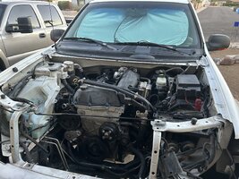
I recently picked up an 02 TB for my daughter to drive when she turns 16 early next year. Had 193k and needed a little work but ran and drove and was only $1500. Body and interior are in great shape and thought we got a great deal.

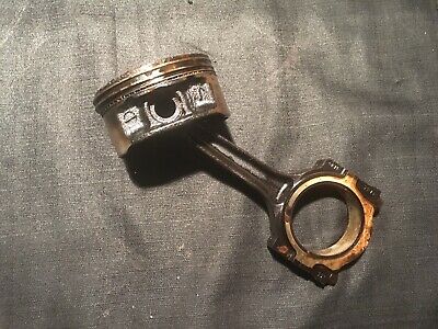
Got it home, changed the oil, air filter and spark plugs and topped off the tranny fluid. Took it for a test drive and engine died down the street and wouldnt restart. Engine seized up and wont turn over by hand 😭 turned out to be a spun rod bearing on #3 cylinder.

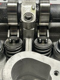
Fast forward to me reading alot of stuff on the web, including this forum and MRRSM’s thread on his rebuild. I currently have the engine down to bare block for the rebuild and found that my cylinder sleeves were scored and one had a crack. Sooo, I sourced the kent moore cylinder sleeve tool and the melling replacement sleeves (along with alot of other parts I have been gathering) which arrived Friday.

I was able to pull the factory sleeves with no issues (like butter!), but am struggling with the install of the new sleeves. I cleaned the bores in the block and the new sleeves, but the first one got down to about an inch out of the hole and became really difficult to turn any further. I tried a second sleeve/bore and it went in an inch or so and again is really hard to crank the ratchet. I don’t think it should be that hard to crank.

Can anyone provide any insight on this part of the procedure that might get me over the hump? Wife is already ready to kill me on this project 🙈 Thanks!
 

mrrsm

Lifetime VIP Donor
Supporting Donor
Member
Oct 22, 2015
7,745
Tampa Bay Area
Removing the *STUCK* New Melling Cylinder(s) will probably damage them around the lower Cylinder Rims with contacting the Extraction Plate and Acme Threaded Rod - Puller. So, obtaining other replacement Cylinder(s) might be in order. The SOP for installing these Melling Cylinders ordinarily Does NOT require using either a Lubricant or by altering the Thermal Conditions happening in between the "Lost Foam" Engine Block Cylinder Receptacles and the New Melling Replacement Cylinder(s).

However... WHAT FOLLOWS SHOULD ONLY BE ATTEMPTED IF YOU ARE WILLING TO ASSUME FULL RESPONSIBILITY FOR ANY NEGATIVE OUTCOMES:

(1) Obtain a 6 pack of "CANNED AIR" which is nothing more than Cans of Liquid R-134A.

(2) Remove the Melling Cylinder from its Box and Brown Rust-Proofing Paper and then Spray Clean those Cylinder Sleeve(s) ...Inside and Out... with BRAKE-KLEEN.

(3) Obtain a Micrometer Caliper Tool with a sufficient Opening Width to measure the Outside Diameter of the Melling Replacement Cylinder AT ROOM TEMPERATURE.

(4) Then... Liberally Spray down the Melling Cylinder Sleeve inside and out with the "Canned Air" and then immediately TAKE A MICROMETER MEASUREMENT OF THE SLEEVE OD.

(5) Compare the OD measurement between the Ambient Room Temperature Measurement and the Ice Cold Measurement of that Cylinder. Practice using this Technique several times and then finish up by spraying down the Melling Cylinder Sleeve with WD-40 Water Displacing Lubricant and then re-package it into its OEM Melling Box and Paper. When it comes time for the Installation... Clean those Cylinder(s) Sleeve again with BRAKE-KLEEN Prior to continuing.

(6) Note the Measurement Differences as being substantial enough to REALLY Matter and ensure that you are well prepared with the Acme Screw Cylinder Sleeve Installation Tool Kit Set Up to immediately tighten it down with a regular tightening action...WHILE SPRAYING DOWN THE INSIDE OF THE MELLING CYLINDER WITH "CANNED AIR"... it should remain Cold enough during this action and thus ...Remain Shrunken Enough... to send that Cylinder All The Way *Home* Down inside of the Engine Block.

(7) Be certain NOT to Stress or Warp the Shape of the Engine Block while performing this work as it will become easily Mis-Shapen by excessive, external manipulation and thereby Change the Shape of the Cylinder Receptacle Holes. Working with an Assistant will improve your Odds of Success... along with having a Proper Plan with the Proper Execution of this Idea. Do NOT Exceed the Low Torque Specs for the Four Engine Block Mounting Bolts holding the K&M 4 Post Install-Remove Cylinder Jig in Place upon the Upper Engine Block!

(8) Do NOT perform the Cylinder Sleeve Upper Ledge Trimming action with the Drill Cutter Equipment from the K&M Cylinder Installation Kit until ALL Six Sleeves have been completely installed into the Engine Block... and only then after the Engine Block and All Cylinders have achieved the same Ambient Room Temperature. The Engine Block MUST be properly restrained while performing the Cylinder Upper Ledge Trimming Actions.

(9) DO NOT OVER-DO THE CYLINDER LEDGE TRIMMING ACTIONS... TAKE YOUR TIME, USE THE PROPER DRILL-SHAVING TECHNIQUES AS PER THE K&M INSTRUCTIONS AND USE A LEGIT HEAVY STRAIGHT EDGE AND BRIGHT FLASHLIGHT TO CHECK YOUR PROGRESS.

(10) DO NOT BE TEMPTED TO USE A PROPANE TORCH TO HEAT THE ENGINE BLOCK IN LIEU OF COOLING DOWN THE SIX CYLINDER SLEEVES... LEST YOU RISK CRACKING THE INNER ENGINE BLOCK LATTICES.
 
Last edited:

Gfmdesign

Original poster
Member
Nov 12, 2023
15
Phoenix
Ok, noted. Do you think I definitely have to remove/replace the partially installed sleeves?

How ‘hard’ should it be to turn the press bolt when instaling the new sleeve? I have a 1/2” ratchet that extends to 15ish’” and am having to pull pretty hard! Having trouble bracing against the block/engine stand doesnt help. Thank you!
 

mrrsm

Lifetime VIP Donor
Supporting Donor
Member
Oct 22, 2015
7,745
Tampa Bay Area
The relationship between the tightness and *Fit* of the Steel Cylinders nested inside of the Aluminum-Silicate Engine Block should be VERY Snug... But ...if your *instincts* are WARNING You that it is requiring TOO MUCH Torque to make the Cylinders "head" downwards into the Engine Block ... then FOLLOW YOUR INSTINCTS. I would urge that you Remove the New Melling *Stuck* Cylinder and discard it if the lower Rim suffers ANY damage. If NOT Damaged... Re-Use it with the previously described "Cold Installation" Technique.

There is NOTHING preventing you from taking that K&M Tool Kit in its entirety along with the Six Melling Cylinders and the Bare Aluminum Block (Weighs about 90 Lbs) to your Local Machine Shop after calling and consulting with them about finalizing this work for You. It seems to me that the results of ensuring a Great Re-Build make this idea worth the pursuit... and "Paying an Expert" to ensure SUCCESS, if needs be... Makes Perfect Sense. :>)
 
Last edited:

mrrsm

Lifetime VIP Donor
Supporting Donor
Member
Oct 22, 2015
7,745
Tampa Bay Area
One last suggestion in support of engaging a Machine Shop to assist you here...

The Melling Cylinder Sleeves will all require a Plateau Honing and the use of a 400 Grit Carbide Nodular Ball Hone to achieve the correct Hash Angle on the cylinder walls of the New Melling Sleeves. If you obtained the proper Mahle Stock Size GM OEM Piston Set as described in my Build Thread... ask the Machine shop if they can perform the Honing of the Melling Stock Cylinder Sleeves by providing them with your New Pistons and matching New Stock Mahle Moly-Ring Sets and perform all of these sizing and measurement actions BEFORE they install the New Cylinders into the GM LL8 Engine Block.

They may decide it is necessary to perform the Cylinder installation FIRST. Nonetheless... This will give you the chance to Kill Three Birds with One Stone. Otherwise... it will fall upon YOU to continue doing this otherwise Very Fine Metal Working of getting the Pistons to Cylinders to Rings Gapping Preparation properly sorted out.

Incorrectly or improperly honing those Melling Cylinder Sleeves will make *seating* the Moly Rings almost impossible during the initial Start Up and subsequent engine runs and thus, the Motor may never develop any acceptable level of Compression. I wish it were otherwise... but NONE of this part of Engine Re-Building is either easy or trivial in any way.

41590374800_5c5821b63f_c.jpg42494501705_3e660b80ca_c.jpg42494501725_423f77e0ee_c.jpg43350756672_b39322b434_c.jpg43350756822_d065b42831_c.jpg43350757362_485b161f6c_c.jpg43350758312_74005e4a14_c.jpg43350758402_a89fb682e3_c.jpg43350763742_bb9aa3457c_c.jpg43350763842_6df5969651_c.jpg43350764032_468752ffeb_c.jpg
 
Last edited:

mrrsm

Lifetime VIP Donor
Supporting Donor
Member
Oct 22, 2015
7,745
Tampa Bay Area
A Bit More Information...

If you've Spun a Connecting Rod Bearing... examine the Rod AND the Crankshaft Journal for "Blue-Ing" as this would indicate that the metal properties of the Con-Rod (and perhaps the Crankshaft Journal) have been irreversibly altered or weakened by Very High Temperatures.

THIS eBay Listing will provide you with a suitable Replacement Connecting Rod. If you can see ANY Blue-Black Staining of the Crankshaft Mains CAPS in your Engine...You would be wise to have the Block checked for Damage and Spin Out of the Aluminum Bossing... and the Crankshaft for Journal Damage. Line Boring the Engine Block with the OEM Mains Caps installed may become necessary:


s-l1600.jpgs-l1600AA.jpgs-l1600BB.jpg

After pulling the Cir-Clips & Wrist Pin and thoroughly cleaning and inspecting this Rod for Damage or Twisting, then Discard THIS Piston and Rings and Do NOT Re-Use the Con-Rod TTY End Cap Bolts. Replace them with GM OEM versions like THESE:

29528236918_7839e6acea_c.jpg

Bear in mind that the Weights of the Complete Pistons, Wrist Pins, Cir-Clips, Con-Rods and Rings must all be within a certain Matching Balance Weight:

More Selections for Pistons & Rods at eBay:


For Additional Brand New OEM Replacement Parts and Fasteners...Visit my *Flickr-Bucket* HERE:


Last edited:

mrrsm

Lifetime VIP Donor
Supporting Donor
Member
Oct 22, 2015
7,745
Tampa Bay Area
Ordinarily... in order to transfer the Heat of Combustion effectively in between the Chilled Cast Iron or Steel Cylinder Sleeves to the Coolant Column... you must have an "Interference Fit" of around 1,000th of an Inch that guarantees this thermal transfer action can occur in a uniform way between Steel or Cast Iron...and Aluminum.

The difficulty arises though if the roughness of the Outer Flanged Cylinder Sleeve disagrees so much in between the receptacles in the Aluminum Block and so the "Chatter" that can happens both when when removing the Old Sleeves... but most particularly when trying to install the Brand New Melling Cylinder Sleeves.

The Pro Shops that work on Cast Iron Blocks can easily sidestep this issue by employing the use of Liquid Nitrogen. The idea is to allow the Engine Block to remain at Room Temperature while submerging the Cylinder Sleeves into the Ultra-Cold Fluid. Once the *Boiling* action STOPS... then the Cylinder is ready to be plucked out of the Liquid Nitrogen and uniformly and smoothly inserted down inside of the Clean, Non Lubricated Engine Block Cast Port Hole.

Then a Standard Weight is set atop the Cylinder to prevent it from retracting upwards while it assumes the same temperature as the Aluminum Engine Block. I have NOT seen this technique being used with Aluminum Engine Blocks so it may NOT work in this identical fashion.

This Video provides more Technical Information and a Live Demonstration of all the steps involved. Handling Liquid Nitrogen is DANGEROUS and should the material splash into your Eyes or on Bare Tissue Surfaces... the Super Cold Liquid will DESTROY those Tissues! Ergo, I am NOT recommending that any Lay-Person perform this work!

 
Last edited:

Gfmdesign

Original poster
Member
Nov 12, 2023
15
Phoenix
Thank you for all the detailed info in your replies and apologies for taking so long in being back on here!

I am fairly certain I have found the cause of my difficulties. After breaking a couple bearings on the tool and attempting the canned air cooling with no success. I started racking my brain again and decided to measure the old cylinder sleeves that I had pulled out and compared them to the new melling sleeves. There was a decent amount of difference!

In my non-stop googling I happened upon the original GM part number for the replacement sleeves and ordered a set. It took several weeks to ship and they finally arrived today. Here are some pics of the differences between the OEM GM replacement sleeves and the latest iteration of the melling sleeves as sold on Rockauto.

IMG_7532.jpeg
IMG_7531.jpeg
IMG_7525.jpeg
IMG_7528.jpeg
IMG_7527.jpeg
IMG_7529.jpeg
IMG_7530.jpeg

It appears that the currently sold melling sleeves are not intended for direct replacement with the kent moore tool and definitely require machining the block as well as the sleeve bore for the pistons. 😩

I forgot to mention in the original post that after seizing the engine I had found a used engine locally for $500 that turned over freely. However upon breaking it down I found the sleeves were scored and the piston tops had small dings. So lucky for me (or unlucky really) I had two engines on hand and was able to clean up that one as well for resleeving.

I had it mostly ready to go when the new sleeves arrived today so got right on attempting to install a new sleeve after measuring and taking the pics above. And wouldn’t you know it went right in with ease! Eureka!

Hopefully the rest of this project goes a little smoother after this damn fiasco!
 

mrrsm

Lifetime VIP Donor
Supporting Donor
Member
Oct 22, 2015
7,745
Tampa Bay Area
Nicely Done on NOT "Giving Up The Ghost" with this issue. You've probably already done this part ... But if NOT... get some Fresh ID Cylinder Bore Measurements with a Quality Snap Gauge and then run it through a Decent OD Micrometer taking your Measures at 90 Degrees to each other, Top, Middle and Bottom of Each New Sleeve, ... in METRIC MEASUREMENTS... ONLY... Just to be certain of the ID Specs on those "GM Slug Holsters" ... the Box Carton Markings for your GM Sleeve shown below indicates that... They might be Bored Thirty Over for accepting The Bigger Mahle Slugs:

IMG_7532.jpeg

Can you say if those GM Cylinder Sleeves have already been Pre-Honed and are Ready for Piston-Ring Set Installation? If NOT, investigate performing a Hone LIGHTLY scrubbed out with a 400 Grit Carbide Ball Hone and definitely use some Honing-Cutting Oil to ensure a Good Break-In and eventually a Good Seal of the Moly Low-Tension Compression Ring Sets.

One Last Observation on the Extra Thick OD... it may well be that those Cylinders WILL fit easily inside of the Later Model LL8 4.2L Engine Blocks, since there are subtle differences between the Two Engine Variants. More investigation would be needed to confirm this as being the issue... but you CANNOT go wrong by using the GM OEM flavors...especially after sliding the Test Cylinder in so easily (Hopefully... Not TOO Easily while using the K&M Four Post "ACME" Screw Jig Pressure Plate to coax them on home).

For others looking around for a similar GM Cylinder Replacement Set... Check Out many of the GMPARTSDIRECT Houses On Line ...Like THIS One... for Best Price & Availability:


51-1tT3kn1L._AC_SL1500_.jpg51sBAOyx+UL._AC_SL1500_.jpg
 
Last edited:

mrrsm

Lifetime VIP Donor
Supporting Donor
Member
Oct 22, 2015
7,745
Tampa Bay Area
This is the K&M PDF Instruction Manual with Universal Instructions for the GM-GMC Atlas Engine Aluminum Engine Block(s) Steel Cylinder Removal and Installation Procedures. I realize that you have probably obtained the R&R Instructions as part of The K&M Kit packed along as a Spiral White & Black Notebook included inside the Black Plastic Blow-Molded Case. But if NOT... THIS PDF IS WORTH ITS WEIGHT IN SOLID GOLD as THE Perfect Reference Guide:


Attachments

  • LSJ_Cylinder_Sleeve_Removal_Install_Instructions.pdf
    403.4 KB · Views: 0

mrrsm

Lifetime VIP Donor
Supporting Donor
Member
Oct 22, 2015
7,745
Tampa Bay Area
As a Follow Up to @Gfmdesign 's Thread... I wanted to ensure that I took the time to verify all of the advantages his discovery might bring to the process of Re-Building the GM Atlas Vortec 4200 Engines (and actually, for the 4 & 5 Cylinder Variants as well). I decided to Spring for a Full Set of GM Replacement Cylinders GM Part# 88984239 and then examine them for Answers to these two very important Questions about their unique factory artifacts... And Hopefully... Being the Stock ID Measurements... with none of that, "Are They Bored 10, 20, 30 Thousandths OVER the Stock Piston Dimensions?" sort of Nonsense assumed by "Just Guessing":

Question: Are these Cylinders Pre-Machined within the GM OEM Factory Specifications, such that an Engine Builder would feel confident with a Direct Installation using the K&M Cylinder R&R Kit?

Answer: A Resounding YES. Here are the Micrometer Measurements I took and the Images memorializing all of this technical activity:

GM Atlas LL8 Vortec 4200 4.2L Engine Replacement Cylinder:
Internal Snap-Gauge to Outside Micrometer Dimensions: 3 Inches (+) :

First (Mid-Bore) Measurement:

Main Scale: .650”
Thimble Scale:.011”
Vernier Scale: .003”
Total 3.664”

Second (Mid-Bore) Measured at 90 Degrees to the First Position:

Main Scale: .650”
Thimble Scale:.010”
Vernier Scale:.001”
Total: 3.661”

Average of the Two Measurements: 3.6625”

VORTECSPECS0.jpgGM42LCYLINTERNALDAIMETER.jpg

These Measurements were taken with an Ambient, Indoors Temperature of 66 Degrees F and this factors into the behavior of the Snap-Gauge and the 3-4" Micrometer during this procedure.

Question: Are the Cylinder Walls *Finished* well enough (with Fine, Oil Holding Hash-Lines) at the proper angle to accept the Pistons and the Two Top, Low-Tension Molybdenum Coated Rings and allow for a Proper Compression Sealing during the Break-In Period ...without having them be Too Smooth?

Answer: YES, Even though these images do not do this visual impression justice. Please know that the New Replacement Cylinders are covered inside and out with a Light 'Cosmoline' Coating to prevent Ferrous Metal Rusting.

In fact, the ID Tolerances are so close to being "DBOM" Accurate (Dead Balls On Measurement) that I think it would be unwise to do anything more to them than running a 400 Grit Carbide Ball Hone Very Lightly though them with plenty of Cutting Oil as THE Final Cylinder Wall Prep and then Washing them all out with Hot, Soapy Water to remove the Grit and Metal Residue and allowing them to Dry with an immediate light application of Motor Oil (INSIDES ONLY) prior to their installation. Here... See for yourselves:
GM42LCYLINDER.jpgGM42LCYLINDER6.jpg
GM42LCYLINDER7.jpgGM42LCYLINDER5.jpgGM42LCYLINDER4.jpgGM42LCYLINDER2.jpgGM42LCYLINDER1.jpgSNAPGAUGES1.jpg


GM42LCYLINDER3.jpg

NOTE:

It makes Perfect Sense that GM would have these Replacement Cylinders all Prepped and Specked Out in advance, because the Average Engine Shop in a Dealership would not necessarily have the time to mess around with Post Sales Machining. This is because it is actually possible to Install these Cylinders into an Engine with it still inside of the Engine Bay and the K&M Cylinder Removal and Installation Manual makes no mention of performing any Post Honing of these "Slug Holsters" at any point in the R&R procedures.

As far as I am concerned, ALL Engine Builders should ALWAYS make multiple measurements of EVERYTHING prior to Final Engine Assembly. In the case of THESE Cylinders... they have come straight from the Dealership, and apparently as now proven ... Really ARE Ready for their Direct Installation! It follows on that it will still be necessary to Fit & Gap the Mahle Piston Rings for the OEM Graphite Coated GM-Mahle Pistons as a very necessary step during this process.

I'm including my GM Atlas Vortec 4200 Engine Specifications PDF attached below that has all of the relevant Motor Measurements, Dimensions and Critical Engine Component Assembly Torque Specifications as well:
 

Attachments

  • VORTECMEASUREMENTS.pdf
    115.4 KB · Views: 6
Last edited:

mrrsm

Lifetime VIP Donor
Supporting Donor
Member
Oct 22, 2015
7,745
Tampa Bay Area
I decided a Follow Up Inside Diameter Check Measurement on at LEAST Three of the Six factory Prepped Cylinders was in order, using a completely different choice of a Fowler Snap-Gauge and a different Fowler 3-4" Outside Micrometer. This was necessary for building even more confidence in what had arrived packaged up in Mixed Makes of Protective Brown Waxed-Lubed Paper, straight from General Motors via GMPARTSDIRECT.

Nonetheless, all of the Cylinders "Miked" out right at 3.664" at Room Temperature using the Same Technique of taking these measurements in Mid-Cylinder in Two Different Locations, 90 Degrees from each other. These are VERY Satisfactory Results... However....YMMV:

Fowler 3-4" Outside Micrometer vs. Fowler 12" Collapsing Snap Gauge
Main Scale: .650"
Thimble Scale: .010"
Vernier Scale: .004"
-------------------------------
Total 3.664" ID


. INEWFOLWER1.jpgINEWFOLWER2.jpgINEWFOLWER3.jpgINEWFOLWER4.jpgINEWFOLWER5.jpgINEWFOLWER7.jpgINEWFOLWER8.jpgINEWFOLWER9.jpgINEWFOLWER10.jpg

As mentioned previously, in ALL cases for this type of Cylinder R&R, every responsible Mechanic should always be taking their own measurements. The reasoning here is that these components Do NOT necessarily come from the same Machine Shop Batches prepared by the same personnel. GM Shipping Fulfillment sometimes has to "Look Around" in order to compile an Order and thus, what you see in the image below CAN happen.

This observation is borne out here by noting the Lubed Brown Paper Protective Wrapping found on these Cylinders is NOT Identical. Small Things like this one matter in Engine Building, so it worked out well that in spite of this seemingly "trivial" difference, all Three Cylinders still "Miked Out" within Factory Specifications.


INEWFOLWER11.jpg
 

Gfmdesign

Original poster
Member
Nov 12, 2023
15
Phoenix
Great info, thank you MRRSM! I did not get alot done for several weeks with the holidays and everything. Finally got around to getting some install work done.

Got the sleeves installed and trimmed. Cleaned up the block again and moved on thru the new bearings, rings and piston install. Everything went well there and crank turned smoothly.

Put the new (reman) head on and new timing components installed. Turned the crank 14 times and everything was still lined up! After that I noticed one of the rocker arms was a little loose and found it was missing one of the retention tangs 😩. Did a couple more crank rotations and closer inspection of all the rockers and lifters and found one of the lash adjuster/lifters also seemed to be collapsed/defective and not holding the rocker up.

Ordered a rocker and lifter and the kent moore tool off ebay to replace those pieces. Hopefully I can keep trucking along without any further issues after those parts come in.

Looking at reman torque converters when I get around to install. Are the TC Remanufacturing converters from Rockauto a suitable unit? Or should I stick with a GM reman unit? There is a substantial price difference!
 

Attachments

  • IMG_7651.jpeg
    IMG_7651.jpeg
    548.2 KB · Views: 6
  • Like
Reactions: mrrsm

mrrsm

Lifetime VIP Donor
Supporting Donor
Member
Oct 22, 2015
7,745
Tampa Bay Area
Congratulations on Making Excellent Progress...

Forgive me for delving in deeper into this Off Topic issue... but the ONLY ways that an OEM Stamped Steel Roller Rocker can become damaged in this manner are if:

(1) The Valve Spring Retainer is Damaged, Misaligned or Improperly Installed.
(2) The Hardened Keepers are either the Wrong Angle & Size, Damaged or Mis-installed.
(3) The Valve Spring Is BROKEN causing the Retainer to CANT SIDEWAYS, as in your case.

Please examine the Red Highlights I added over your Original Image to emphasize just how much the Valve Stem moved often enough over to the RIGHT to cause the Tip of the Valve Stem to become ROUNDED OFF from getting hammered by the Misaligned "Claw" wearing them BOTH down over time.

The resulting Metal Fatigue evident here caused the "Claw" on the Right Side to Break Off. Hopefully, this Engine Head is NOT presently Installed and you can easily remedy the problem after removing the Keepers, Valve Spring Retainer AND Valve so you can examine the Valve and the Combustion Chamber Valve Seat for additional damage from this Misalignment problem:

IMG_7651A.jpegIMG_765B.jpeg

I have three other contemporary Thread Contributions that are relevant to this issue and may be worthy of your attention and helpful in this circumstance:


Last edited:

mrrsm

Lifetime VIP Donor
Supporting Donor
Member
Oct 22, 2015
7,745
Tampa Bay Area
If the Engine Head is presently installed on the LL8 Engine, there is a strong possibility that this particular Red Highlighted Valve shown above has been getting repeatedly canted off to one side and thereby get held Slightly More OPEN due to the Tip of the Valve Stem getting hung up underneath the Right Claw of the Roller Rocker.

It follows that the Valve Stem may also be BENT as a result of the Valve striking the Underside of the Right Claw AND allowing the Valve to strike the Piston Top in the exact location of that particular Valve. Such repeated impacts upon the same Spot on the Piston Head over and over might generate enough mechanical force necessary to eventually Break Off the Right Claw:

Look Closely at this Image to see the distinction between the Canted Keeper and the Rounded Off Tip-Edge of the Valve Stem (Tilting FORWARD) adjacent to the Broken Off Right Claw marked with RED ARROWS...vs... the Twin Adjacent Arrangement at its Right Side...with its Well Aligned Keeper and Valve Spring and its Sharp, Well Hidden, Clearly Defined Edge of the Valve Stem Tip in between the Two Claws and marked with BLUE ARROWS:

IMG_7651C.jpg


If this is the case, it can easily be discovered by unwinding the Spark Plug on that Cylinder and inserting a 7mm to 9mm Bore-Scope down inside to investigate the Piston Head AND to examine he Upper Combustion Chamber for indications that the same Valve has NOT been seating properly within its Pressed-In, Three Angle Steel Valve Seat.
 
Last edited:

Gfmdesign

Original poster
Member
Nov 12, 2023
15
Phoenix
Been busy, but got some work done. That head was freshly reman’d and I think the pic lighting was doing some weird things, plus there was assembly lube and some fresh oil on a lot of it. I checked all of the other springs and retainers and everything looked good. I did replace the one rocker and a valve lifter and moved on. That head was already bolted down but nothing had been run yet. No idea how or why that one rocker broke the tang.

I have since finished the entire engine assembly, bolted the transmission (I had also rebuilt) up to it, and dropped the whole thing back in the truck. Took some effort and a couple extra sets of hands but made it in.

This past weekend I finished putting all the other components in, filled up fluids and finally got to start it. Started right up, no odd noises and seems to run excellent thus far! Revs well and idles smooth but does have a slight hesitation just off idle when you first press the accelerator.

I am having an issue with the trans though 😩. It will only move in reverse, 2 or 1. D and 3 it acts like its in neutral. I did a short drive around my block and it runs smoothly but does not shift. Fluid checks the correct level hot and does rise after the engine is shut off so I am pretty sure the pump is working. Trying to do some searching to see if I possibly installed something incorrectly or a part is bad. I am hoping I dont have to pull the trans back out.

Thank you for all the help to this point!
 

Attachments

  • IMG_7703.jpeg
    IMG_7703.jpeg
    608.1 KB · Views: 5

mrrsm

Lifetime VIP Donor
Supporting Donor
Member
Oct 22, 2015
7,745
Tampa Bay Area
If you are fortunate enough to have either a "GYMKO" (General Motors Knock Off) Tech 2 or an Autel Maxi-DAS DS708 Scan Tool... you can perform a CASE Relearn that might reconcile the Idle Issues.

As for the Transmission Shifting issues... the Stock Stall Speed is unusual for the GMT360s in the range of 2400 RPM... so if the Transmission Re-Builder installed a DIFFERENT Torque Converter than the OEM version...that might be part of the non-shifting into overdrive issue. We have some very clever Folks here at GMT Nation that can help you delve deeper into the 4L60E Post Engine Install Transmission issues.

Congratulations on your Final Engine Assembly and Successfully Starting everything up. I'd Bet a Brace of Gutenberg Bibles ...that your "Out Of The Box" Compression was already very close to 10:1 with those New GM OEM Cylinders being Pre-Honed to assist with Engine Break In. Don't forget to Change your Oil and Oil Filter to New Amsoil Break-In Motor Oil at around 500 Miles... and then switch back over to Mobil1 5W-30 Motor Oil and a Mobil1 Oil Filter at around 3,000 Miles.

You could easily confirm this by performing a Relative Compression Test with a PICO-Scope Model #2204A Oscilloscope & PICO-Scope Automotive Diagnostic Suite (Ver. 6) married via the USB with a Windows Laptop & a Hantek Model # CC-65 Low Amp Clamp around the Starter Cable would reveal just EXACTLY how even all Six Cylinders are during the Amperage Draw for the first 10-15 Seconds of Turn-Over. Refer to THIS Link for more information:


Mooseman

Moderator
Dec 4, 2011
25,355
Ottawa, ON
Have you tried scanning for codes? Usually when it won't shift up, it's basically in limp home mode and just stays in second gear. This usually happens when the tranny connector is disconnected, the fuse for the tranny is blown or there is an issue with the wiring and power is not getting to it.
 
  • Like
Reactions: mrrsm

Gfmdesign

Original poster
Member
Nov 12, 2023
15
Phoenix
I do not have a Tech 2 or similar scanner, however I do have a EFI Live Autocal and when hooked up with my laptop I have some capability for idle/CASE relearn. I will give that a go.

As for the trans, I was the rebuilder (my first). I did order the proper coded torque converter for it. Had to go with a reman one from Rock Auto and opted for the TCI one vs the GM one strictly for price at this point. Typically I always go for OEM stuff.

I did check for codes today and got

U1000
B2470
B0408

Not sure on the U code. B2470 is the onstar antenna I believe. I removed the old school cell phone antenna from the rear window so I assume thatbis the cause. The B0408 is related to the blend door actuators.

Yesterday I had more, but cleared them out and only the three above returned. Even the readout from yesterday did not show the others as current. Not sure at this point.
 

Attachments

  • IMG_7714.jpeg
    IMG_7714.jpeg
    627 KB · Views: 2
  • IMG_7711.jpeg
    IMG_7711.jpeg
    393.6 KB · Views: 2

Gfmdesign

Original poster
Member
Nov 12, 2023
15
Phoenix
I think the U1000 is related to the B2470 onstar deal. I thought the U1000 usually coincided with another code for whatever module was having issues? I would think if it were trans related it would pop a trans code right?
 

azswiss

Member
May 23, 2021
881
Tempe, AZ
In the image above U1000 is being flagged by the PCM. It gets triggered if/when there is a communication malfunction between modules on the network. It can cause problems such as no start conditions, intermittent stalling, loss of instrument cluster functionality, or erratic behavior of the transmission.

I am with @Mooseman on this, check the transmission connection (both sides of the connection, e.g. missing bent pins, proper seating), fuses, and wiring integrity in/around the transmission.
 
  • Like
Reactions: Mooseman

Mooseman

Moderator
Dec 4, 2011
25,355
Ottawa, ON
It's possible that the OnStar module has gone bad and interfering with the network. You should go under the rear seat and disconnect it completely just in case. Since its an old analog unit, there's no point in having it drawing power.
 

mrrsm

Lifetime VIP Donor
Supporting Donor
Member
Oct 22, 2015
7,745
Tampa Bay Area
A Few More Suggestions:

(1) Obtain a Can of CRC Electronic Spray Solvent:

CRCELECTRICALSOLVENT.jpg

(2) Try Unplugging the 20 Pin "Squeeze & Lift" Main 4L60E Transmission Harness Plug situated on top of the Upper Passenger Side Ledge...

aa792f2a12b2f54306c32030eebc9eeb.jpg

clip0166.png

(3) Liberally Spray Out BOTH Sides of the Plug Male and Female Receptacle and allow them to thoroughly DRY...and then Plug them Back Together.... Start The Vehicle AFTER Clearing the Codes and take a Short Test Drive cycling though the 4L60E A4 Gears...Plus Park & Reverse.
 

Attachments

  • 4L60E20PINPLUG.jpg
    4L60E20PINPLUG.jpg
    50.4 KB · Views: 1
Last edited:
  • Like
Reactions: Mooseman

Gfmdesign

Original poster
Member
Nov 12, 2023
15
Phoenix
Well I got it figured out. Had a PM conversation with MaroonMonsterLS1 and he thought it was most likely the input sprag installed backwards.

Being my first attempt at a transmission rebuild I watched the videos from Transmission Bench as I did it. Thought I had the input sprag correct, but after pulling the trans out again and opening it up, I found that I had in fact put it in backwards 😩. Got it in properly and reinstalled the trans today. It works properly!

Drove the trailblazer around quite a bit today and had it pop a check engine light. P0014 for the CPAS. I put all new AC Delco sensors in it when I did the engine rebuild. My scanner/tuner that I have does not have the ability to do the CASE relearn on the Trailblazer like it will on my Tahoe and Silverado. Could needing that CASE relearn done cause this code or am I looking at something else?

Runs really smooth and powerful with occassional hesitation when taking off from idle.

Thanks all!
 
  • Like
Reactions: Blckshdw and mrrsm

mrrsm

Lifetime VIP Donor
Supporting Donor
Member
Oct 22, 2015
7,745
Tampa Bay Area
Unless you replaced the Original CPAS Unit with a Brand New Component... and just forgot to change your Break In Oil and Oil Filter at the same time... The Residual Engine Builder's Assembly Lubes like Lubri-Plate or Permatex or even the similar stuff sold by Harbor Freight such as Molybdenum Di-Sulfide Grease might be so viscous as to work their way into the CPAS and clog up the Screens.

Also, if residual Carbon somehow managed to also migrate through the Oil Galleries and wind up in there and if the required 7 Quarts of Oil is also not met, Old Carbon Grit and Low Oil Volume can also trigger a P0014 as well, so a quick check on the Dip Stick will remove all doubt:


Bear in mind that dramatic changes in engine components that improve performance can also have a down-hill effect that might not be anticipated. These include such things as having a Brand New Oil Filter getting clogged up with Moly-D Grease used during Engine Assembly. As always, these are things that can easily be attended to with having a Mindset of, "It's Better to Be SAFE Than SORRY...".

Changing your Transmission via Re-Build or Replacement would call for the use of a Bi-Directional Scan Tool to perform a CASE Re-Learn that will lighten your Wallet by $100.00 at a Qualified Shop or Dealership. On the UP side though...Doing so will show that your Engine Work will make the average ASE Mechanic with a Tech 2... Absolutely GREEN...with ENVY. :>)
 
Last edited:

Gfmdesign

Original poster
Member
Nov 12, 2023
15
Phoenix
Ok got the crank relearn done at a local shop for $20. Oil and filter have been changed and I even pulled the CPAS and cleaned it (still looked brand new 🤷🏻‍♂️). Code P0014 still persists.

Is there a chance the new GM CPAS is just a bad part? The shop guy thought it could be the cam actuator itself, but its a new Dorman part from the rebuild. Wish they had not discontinued the GM actuator!
 
  • Like
Reactions: mrrsm

mrrsm

Lifetime VIP Donor
Supporting Donor
Member
Oct 22, 2015
7,745
Tampa Bay Area
With the CPAS and Oil Pressure Issues Sorted ... if the CPS has not as yet been replaced with a Brand New Sensor, the specific Camshaft (Absolute) Position Sensor Code P0014 is remedied as follows:


Don't forget to Clear the Codes...
 
Last edited:
  • Like
Reactions: Mooseman

Mooseman

Moderator
Dec 4, 2011
25,355
Ottawa, ON
I have used a Dorman phaser without any issues after the ACDelco rebuilt one failed (they never sold any new, just rebuilt).

Which CPAS brand did you use? Not sure if GM/ACDelco are still available. Some aftermarket ones are of lower quality with components that can be rotated after it's installed.
 
  • Like
Reactions: mrrsm

mrrsm

Lifetime VIP Donor
Supporting Donor
Member
Oct 22, 2015
7,745
Tampa Bay Area
...and besides confirming that the CPAS is being fed sufficient Oil Pressure using an Analog Oil Pressure Gauge attached near the Oil Filter Manifold, if you need to delve really deep into the full Cam Phaser and CPAS Sensor Diagnostics... look no further than everything covered in this Video:


Attachments

  • 29564782028_bb0d97337e_c.jpg
    29564782028_bb0d97337e_c.jpg
    64 KB · Views: 2
  • 29564785708_8b99044eb0_c.jpg
    29564785708_8b99044eb0_c.jpg
    41.5 KB · Views: 2
  • PXL_20221017_000608683.jpg
    PXL_20221017_000608683.jpg
    447.9 KB · Views: 4
  • CPASOHMSTEST.jpg
    CPASOHMSTEST.jpg
    27.1 KB · Views: 2
  • CAMPHASERDUTYCYCLETEST.jpg
    CAMPHASERDUTYCYCLETEST.jpg
    36.1 KB · Views: 0

Gfmdesign

Original poster
Member
Nov 12, 2023
15
Phoenix
The phaser I put in was a Dorman. The CPAS was Ac Delco via amazon. Gonna get another new one and give that a go. Will dive in to some of the further diagnostics too.
 
  • Like
Reactions: mrrsm

Mooseman

Moderator
Dec 4, 2011
25,355
Ottawa, ON
Amazon is a repository of fake name brand parts so possibly it was some cheap CCC.
 
  • Sad
Reactions: mrrsm

Mooseman

Moderator
Dec 4, 2011
25,355
Ottawa, ON
Same as some ACDelco plugs they were selling at one time.

Was it exactly the same as in the picture, markings and all? It's the same picture as on a GM parts website.
 
Last edited:
  • Like
Reactions: mrrsm

Gfmdesign

Original poster
Member
Nov 12, 2023
15
Phoenix
IMG_7841.jpeg
It was purchased from the same seller as it was out of our ‘buy again’ section in Amazon. Only markings are the stamped numbers, which are different from the image in the ad. They dont correspond to the part number in either case as far as I can tell.
 

Mooseman

Moderator
Dec 4, 2011
25,355
Ottawa, ON
At least the "type" of marking is similar. Could be a serial number or date code.

Are you able to rotate the metal body while it is mounted there? The good ones have slits that won't allow it to rotate within the holding clamp however the cheaper ones will have a groove all around instead which will allow it to rotate.

Another possibility, which has been mentioned by @mrrsm, is a possible issue with oil pressure. Since you were able to get a CASE relearn done, I would not suspect an issue with either the cam or crank sensors.

All this may just be due to a dud CPAS.
 

Gfmdesign

Original poster
Member
Nov 12, 2023
15
Phoenix
Well new CPAS came from Amazon. Had the fancy holographic sticker on the box and looked identical to the one I took out. The numbers stamped on it were different, but again did not match to the part number. Disconnected battery for at least30 mins for the install. During test drive the code popped up again fairly quickly.

The damn thing runs great! No misfire, rough idle or stumble and had lots of power. I can tell after the check engine light comes on that it has a little less power but still runs great.

I have about 260 miles on the first oil change with 5w30 dino oil and an AC Delco filter. I plan to go to Mobil 1 full synthetic and a M1 filter once I get to about 1k miles on it.

I have checked the CPAS harness and have about 11.xx V with key on. I am waiting on the oil pressure adapter fitting to be delivered later this week so I can check the pressure with an actual gauge.

I am stumped on this thing since it runs great and shows no typical symptoms of CPAS problems other than the light. Really irritated!
 

mrrsm

Lifetime VIP Donor
Supporting Donor
Member
Oct 22, 2015
7,745
Tampa Bay Area
From Top Down, Left to Right... This Chart follows the Diagnostic Checks that you have been using so far... or should be, even if it involves investigating the Dorman Cam Phaser, too. If the Timing Chain Set and Timing Chain Tensioner along with replacing the Timing Chain Guides has yet to be done and the Oil Pressure proves to be Nominal at Idle around 12 PSI or Better... THESE Items are the only things involved here that can be wrong...

CAUSESOFTHEP0014CODE.jpg
 

Gfmdesign

Original poster
Member
Nov 12, 2023
15
Phoenix
Well, I was waiting on parts to come in and now think I finally have it solved! Oil pressure was good so I broke down and ordered another dorman cam phaser sprocket and the timing chain holder tools.

Opened everything up AGAIN and pulled the old (new really) dorman phaser and decided to test it with air pressure. It was initially unresponsive with several bursts of air. Finally it seemed to free up and began to move in response to the air pressure. Sprayed some carb cleaner in the port and blew air through it some more to repeatedly activate it. It was moving but seemed gritty.

Tested the new one and it moved appropriately so installed it and buttoned everything up AGAIN 😩 Started it back up and runs well. Drove it around a bit today and so far no pending code or anything. Hoping it holds tomorrow and I can get this thing emissions tested and registered finally!

Ran into a couple issues during my disassembly including finding a leaking water pump and fuel in the vacuum line for the fuel pressure regulator. Both have now been fixed and hoping this is the last of it!

Thank you all for the assistance and wisdom! 🍻
 

Forum Statistics

Threads
23,336
Posts
638,049
Members
18,541
Latest member
33chevyrod

Members Online