This Article is nice Starting Point because it addresses concerns like yours that can occur in general use whenever using Professional Bi-Directional Scanners in the Work Bays of Professional Shops. Remembering that the Men and Women working in these institutions are no smarter or more capable than the person standing to your right or to your left... the Scanners involved as Bi-Directional aspect of these Tools are meant to Side-Step the Ordinary Actuation of the PCM of certain Modules only under certain conditions (including Certain Temperature Ranges ) and to either Prove or Disprove their proper functionalities under such controlled conditions:
The information and products that work alongside your scan tool for a complete repair.

www.vehicleservicepros.com
Doing this investigating while sitting comfortably behind the Steering Wheel with the Bi-Directional Scan Tool Powered Up and attached to the DLC will neither Damage the PCM, nor the involved Modules or other Components being Tested. As soon as any Codes are Cleared and the System is Re-Cycled during Key On - Engine On... or if called for Key OFF Engine OFF set ups, then everything should appear just as before.
However, under certain Testing Conditions...Incidental Trouble Codes might be set DUE to the Testing Procedures that will simply require being CLEARED at the conclusion of the Test Phase. It is very important to Research ALL of the Prerequisite Test Conditions needed BEFORE beginning any such Bi-Directional Tests, thereby avoiding getting any specious responses with the Scan Tool that might skew accurate results. Always Make it a Habit of Checking the B+ Battery Voltage BEFORE hooking up the Scan Tool looking for around something 12.6 Volts DC as a Nominal Condition...and for Extended Periods Testing Time...
Using a Battery Maintainer is a MUST.
By comparison The Average Scan Tool is less of a "Tool" per se... and More of a Mere Code Reader and thus they only display the
RESULTS of a Problem... without defining PRECISELY What has Caused the Problem in the first place. But having a Bi-Directional Capable Scan Tool
WITH a Built-In Regimen of Tests that can be performed in precise ways gives the Mechanic or Diagnostic Technician the added advantage of being able to *get inside* of certain Modules and Commanding them to do certain things and thus, provide a Return Feed-Back to either confirm or eliminate that a Certain Module IS THE ACTUAL CAUSE of the Problem(s)...IF it that Module or Component FAILS the Test.
Sidebar:
At $100.00 a Pop for a Bi-Directional CASE Re-Learn Procedure... or say... For Clearing and Cycling the ABS Module or ABS Codes after Purging Old Brake Fluid ... That Brand New Bi-Directional Scan Tool will soon Pay for itself when you are no longer expecting to be a "Waiting, Impatient...Paying Customer..." at any Dealership or a Pro Shop in Town... anymore.
However... having a decent Bi-Directional Scan Tool is only Half The Battle. In many cases... Further Diagnostic Testing must be done AT THE CONNECTIONS TO INDIVIDUAL SUSPECT MODULES OR COMPONENTS and then observed in conjunction with The New Bi-Directional Scan Tool perhaps along with OTHER Co-related Modules or Components being looked at during this phase of the investigation by using OTHER Diagnostic Tools.
For Example... If your Bi-Directional Scan Tool displays a P1345 Code... it will become necessary to Directly Sample the A/C Signal being Generated by a (CKP) Crankshaft Sensor which can only be registered in sufficient detail on an Oscilloscope. It will appear as a Wave Form showing (58) Segments of Sine Waves on the Screen that measure in at 6 Degrees of Rotation "Per Hump"
(60 Teeth Segments on the Reluctor Wheel with - 2 Empty Segments defining WHERE Top Dead Center is positioned for the #1 Cylinder) .
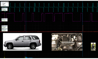
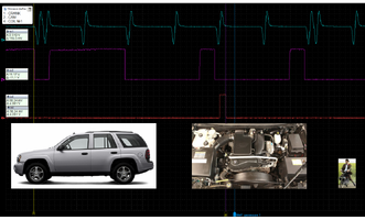
This is all well and good. However, without taking another Oscilloscope Sample for comparison against the (CMP) Hall Effect Square Wave Camshaft Position Sensor say on Channel #2, You will not know what any of its Diagnostic VALUE is in figuring out What is actually Causing the P1345 Code. Here are Two Such Comparisons of a Known GOOD Wave Form vs. a Known BAD Wave Form...NOT readily discernible by the use of a Bi-Directional Capable Scan Tool:
NOTE: The *SIX* A/C Sine Wave Segments shown below in between the Dual Empty Hump Spacing at their Beginning and Ends of the Blue Trace for the Crankshaft are indicative of the Early Model GM LL8 4.2L Crankshaft Reluctor Wheel Cut-Outs located near the 5th Mains Bearings Position in lieu of the Later Model (60) -2 Versions of this Design.
Take Notice of how in the Purple Trace presents with Three Large and Three Small Square Waves present, they represent the identical Positions of the Outer Cam Phaser Notches that likewise register as they pass by the (CMP) during Camshaft Rotations right where the Pick Up is Bolted into the Upper Front Passenger Side of the Engine Head.
Meanwhile, in correlation, the #1 Cylinder at TDC of the Blue Trace should be coincidental with the matching falling and rising edges of those Six Notches. These Two Signals inform the Diagnostician about whether or not these alignments have drifted too much indicating a Stretched, Worn Timing Chain associated with a fully expanded Timing Chain Tensioner and Badly Grooved Timing Chain Guide often evident in High Mileage GMT360 Early Model LL8 Engines:


All Scan Tools show the EFFECTS of such Automotive Problems... while Stand Alone Oscilloscopes and Higher End Scan Tools (Snap-On Zeus, Verus, Solus, Modis,and Vantage PRO Graphing-Oscilloscope Multi-Meter) with their additional Features of having a Four Channel Oscilloscope and a Graphing Multi-Meter Built-In ...along with 250,000 Directed Component Tests are Features that allow them to Hone In on the Precise CAUSES of Failures and then facilitate FAST and ACCURATE Parts Replacements and Other Repairs,


