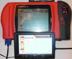
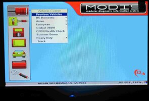
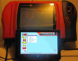
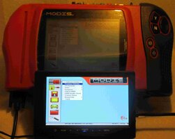
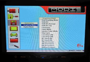
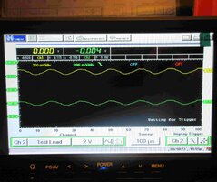
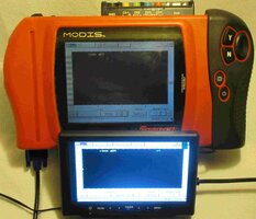
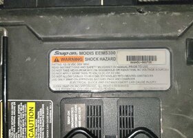
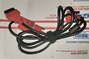
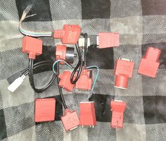
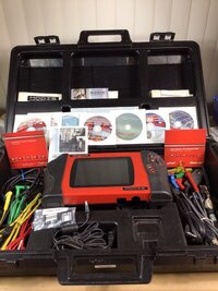
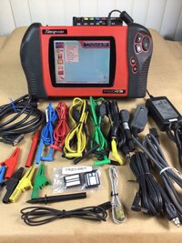
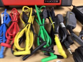
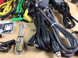
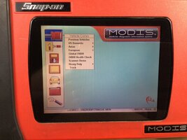
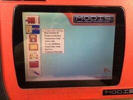
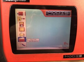
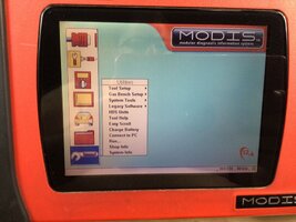
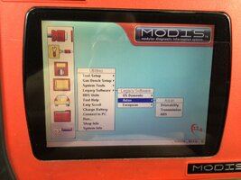
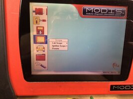
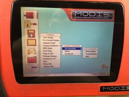
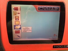
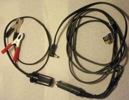
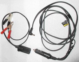
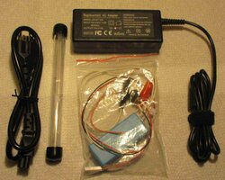
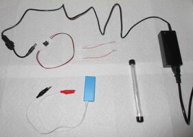
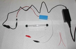
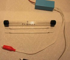
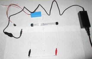
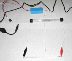
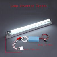
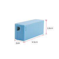
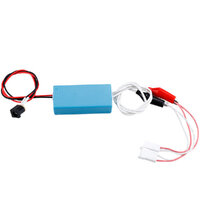
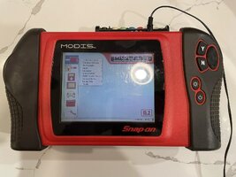
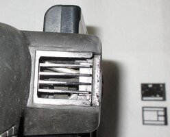
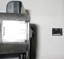
While continuing to delve ever deeper into the "Mysteries of The Snap-On Modis"... I dosed myself with enough of my OWN Medicine so as NOT to assume the the OEM LCD Back-Light Bulb was
THE Cause & Origin of the Low Light appearance of the Screen once the Modis is Powered ON.
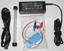
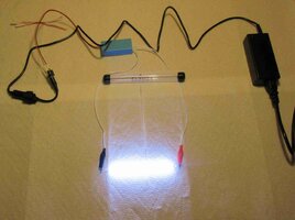
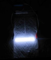
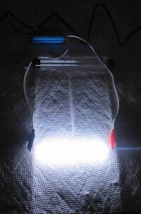
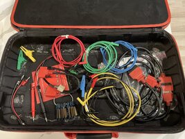
The results actually surprised me in that instead of either NOT working at all, or being so DIM as to prove that THIS was the Problem.... when the CCFL Tester High Voltage Output Power was applied to the Pink & White Bulb Input Wires... The OEM CCFL Lamp Lit up
VERY BRIGHT.
Uh Oh... So if the Bulb (Lamp) is
NOT the actual problem...
then WTF is going on here to make it NOT Work? Hmmm... Time to Tear into the Modis and get into the MOBO and see the Screen Layout inside of this complicated Scan Tool to look things over.
THIS is *STUFF* Worth Knowing ....if you want to repair any "Dead Screens" on your Resurrected Snap-On Scan Tool Tech:
Fortunately... having lived through and learned from the "Post CRT - TV Screen" epoch of having Giant Cathode Ray Tubes Magnetically Guiding an Electron Beam from Top Down and from Left to Right against and across the Phosphorous Coated interior Surface of the Giant Vacuum Tubes of Old..."... when the then NEW (Pre-LED) Cold Cathode Fluorescent Lamp (CCFL) Tech emerged in the Mid-1980s, that saved us all an eye-watering amount of money on our Home Electricity Bills ..
.not to mention greatly reducing the amount of added Thermal Emissions from all of those Old Computer Monitors... and I wanted to Know MORE about the subject.
THIS Tech Advancement allowed for the development of the "Portable Notebook-Laptop Computers" that we still enjoy to this day even when so much more computing power is available in our Cell Phones.
It was also around that time frame that the Snap-On Verus, Solus, Modis Family of Professional Scan Tools
(costing around $10,000.00 to $15,000.00 per Kit depending upon the "Extras" in the Shop Purchases) were emerging in the After-Market Auto Service Industry.
What made this transition possible came from the brilliantly conceived ideas that emerged from The Texas Instrument Company creating Low Power Consuming LCD Screens "In Shades of Gray", made famous by all of those Casio Liquid Crystal Display Wrist Watches and TI-XX Scientific Pocket Calculators that were Pounding the Wrists of a LOT of "Time Conscious" Consumers and getting stolen off the desks of every Engineer and College Kid across North America.
Anyways... The
NEXT Best Idea to emerge was to create the LCD Output in the Three Primary Colors...
BUT... that demanded the additional assistance of having BACK-LIT SCREENS feeding Very Bright Light through either Opaque Plastic or Frosted Glass Back Drops to drive enough Photons ...
through... the Color LCD Panels in order for those colors to brightly display on High Tech Scan Tool Screens.
So getting back to the
"What Went Wrong?" part of this Diatribe... THIS is that very Technology explained in just a few Images and with certain aspects pointed out that went
SIDEWAYS on the Modis Mother-Board that I can easily work around as follows:
First...it is important to explain that the
THINNER the Fluorescent Tube being used is... the GREATER the Electrical Resistance becomes in between the two ends and thus...those "Tiny White Light Tubes" can place a very high demand for High Voltage Output coming from any Rapidly Switching Oscillation Coil.
THIS is what a FAILED CCFL HV Oscillation Transformer Coil surface mounted upon the Snap-On Modis MOBO looks like after the In-Dwelling CCFL Tube got Carboned Up inside and pushed the HV side of the Coil to produce on demand until it got HOT enough to FAIL:
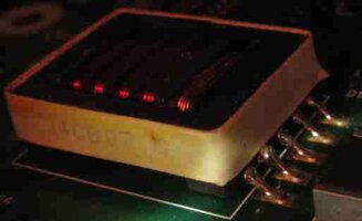
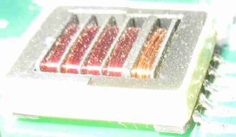
But...since I have been unable to find an OEM Replacement Oscillation Coil EXACTLY like this one that so obviously could be R&Rd as an SMC, my Next Best Idea is to use EITHER an Original, Stand-Alone LCD CCFL Bulb Driver Circuit...or...Switch over to the LED Option and simply find an "Empty Space...Inside The Case" and park a Complete CCFL Driver Unit therein...or...Switch to the Very Fine Versions of the New LED Strips and mount that line of lights along the edge of the 7.2" Scan Tool Screen and Drive the Light independently from a Switched Power Source from the Snap-On Modis MOBO Chassis.
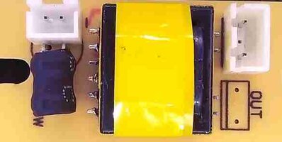
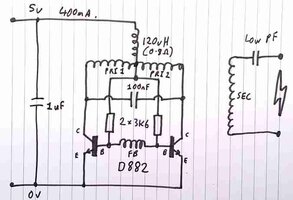
THIS is a Bird's Eye View of what a Classic CCFL PCB-SMC Kit looks like and how it behaves courtesy... a Nice, Little Hand Drawn Schematic:
In a Nutshell... the 5 Volt DC (2 Amps) Input comes in to the Black Resonator on the Left Side of the Board and is *finagled* via a 120 Henry through a few Capacitors while shuttling back and forth between Two NPN Transistors that serves to Jack the Low Voltage-High Amperage Input up to VERY High Voltage @ Lower Amperage in the Secondary Coil Sides on the Right Side of this Tiny Board as a Single HV Output.
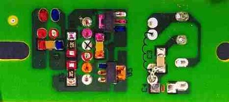
There is a Pico-Farad Capacitor on the Output Side on the RIGHT meant to prevent Sparking even though it has a
VERY LOW Capacitance Level due to the presence of the VERY HIGH FREQUENCY of the HV Output feeding thence into the Pink & White CCFL Tube Power Wires.
That's IT... and THUS... the Snap-On MOBO Circuit can be completely side-stepped by using one of
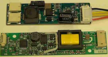
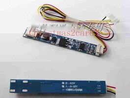
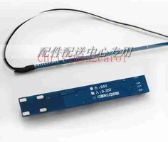
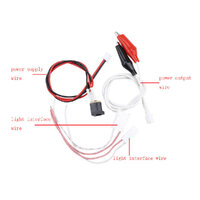
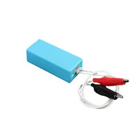
THESE Stand-Alone CCFL or LED Driver Circuit Boards! I have ordered a few more Variations on this Theme because they are very inexpensive to obtain... and one may work better than another when placed inside of the Snap-On Modis Chassis:
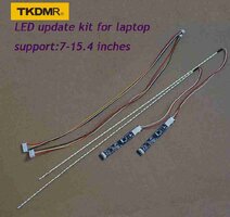
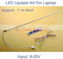
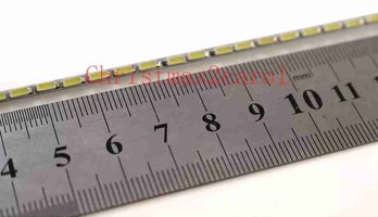
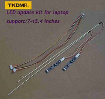
And for the LED Conversion avenue... there are many, ubiquitous LED Driver-Light Bar Kits available like THIS One that can be sized down and still function in the 7.2" Length:
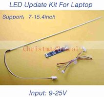
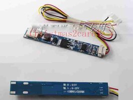
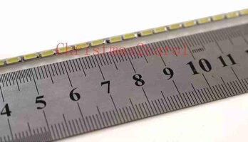
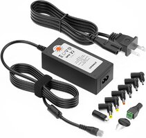
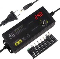
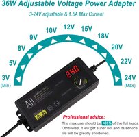
It is NICE to have some flexibility of the Input Voltages as well:
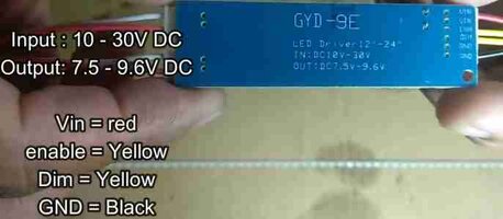
The TOP Board of the two shown below is for the LED Flavor that Drives the Two Tiny LED Light Bars (Dual Outputs). The Bottom Board is the Classic CCFL Driver Board...
Notice the Thermal Sensor leaning up against the Left side of the Oscillation Transformer?
THAT Thermocouple (Thermistor) is meant to sense any impending OVER-HEATING FAILURE as the Brightness of the Color LCD Screen Gradually Diminishes when the Thin CCFL Bulb-Tube begins to FAIL and THAT is what stresses the HV Transformer!
