Reprise's 2003 Sierra Build Project - Blue Crush

Reprise

Original poster
Lifetime VIP Donor
Supporting Donor
Member
Jul 22, 2015
2,724
So, as we all get used to 'life under coronavirus', I've reconsidered having the rear axle noise diagnosed / fixed before beginning my long-planned (and long-promised!) build. Partially, it's because I'm now suspecting that the noise I'm hearing may be U-joint / driveshaft / pinion related, and that whichever it is, it's in 'early stages'. Might be misplaced optimism, but I'm sticking with it, for now.

Which means... this is now a perfect time to start the build, in earnest, since my personal mobility is being limited right now.
- This won't be a 'one-to-two day' project (although I'm sure some of you could do it in that time) -- so, if you're interested in following, you may want to 'subscribe', so that you'll be notified when I post something new / worthwhile.
- For the same reason, don't expect 'daily' updates.
- If you see I've done (or about to do) something 'wrong', don't be afraid to voice your concern. I intend to explain why I'm doing certain steps, as they come along. (but I'm also aware that my postings easily become longish, so striking that happy medium may be a challenge, at times!)

Here's a couple photos of our 'patient'...

As_Purchased_Nov18(approx-unsure).jpg

This first one is how I 'got' the truck. 2003 Sierra 1500HD, with about 230K.
You'll note the C3 / Denali grille / turn signal housings / bumper cover (which is not flush due to the previous owner not using the special brackets required with that cover), along with the H2 rims / big-ass 315/70/16s.
The owner before him had a CB Radio in the truck (that's what those antennas behind the cab are for).
This truck spent the first half of its life in Texas, and there's almost no body rust / only surface rust on the frame. Lucky me.
Those bulging rear fender flares indicate that this truck has Quadrasteer. Thankfully, the previous owners didn't use this for towing boats, as the system is still operable. Incidentally, those flares are... fiberglass, meaning that they'll never rust, like the rear wheelwells normally do. The rest of the bed is steel (and it has a Line-X bedliner, which is in excellent shape, for a 17-year old truck. Lucky me, again.

Over the last several months, I've replaced most of the front suspension, tires / wheels, tailgate (which was dented), the rear axle (a 35-spline Dana 60 with kingpins), new rear hubs (which are like front hubs on a 4WD truck), caught the truck up on maintenance in various other areas, replaced the Flowmaster with a stock muffler / tailpipe, and gotten it to this point:

Feb2020_b4_build(1a).jpg

Yeah, those are Chevy center caps - sue me. LOL Tires are BFG 265/70/17s (highway tread; I tow with this truck, and don't leave pavement). Those are new headlamp / turn signal housings, and the OEM grille / bumper cover. Added a soft tonneau & nerf bars (you don't see the passenger one here, but it's there now)

The gap you see between hood / fender / grille is because I forgot to latch the hood before taking the pic (oops).
I also turned on the QSteer in this pic, to emphasize the 4WS, but you can't really tell, here (it moves a maximum of 14 degrees, so it's subtle). Oh well...
Yeah, it's dirty. Sue me again.

Drivetrain on this beast is an LQ4 6.0L and a 4L80E, to go along with that Dana 60 rear (which has a 4.10 gear). While my previous 1500HD had a lot of torque, compared to the 5.3L Envoy XL I was towing with, this motor is even stronger. Which makes me think it's got a tune, at the very least, and maybe some aftermarket parts. We're going to find out, as I plan to replace / upgrade the following:

- Heads (with new rebuilt 317s)
- Tow cam / lifters / springs / timing set
- Oil pump (not 100% sure on this, yet)
- Intake (and I may relocate the knock sensors to the Gen IV locations on the side of the block)
- Items which get touched on the way to the cam (like the water pump, hoses, etc.
- Tuning / dyno
- Couple addn'l appearance items

All of the above will be on top of the stock (?) bottom end, which has good compression / power / oil pressure, and doesn't burn / leak oil (which is why I may forgo the oil pump upgrade). I also had Blackstone do an oil analysis to make sure that wear metals on the engine looked good before spending $$$$ on this project. After doing the intake gaskets & killing off another vacuum leak or two, this thing is running like a top now (outside of the noise in the rear end that I mentioned at the beginning). But... I want 'more' (typical American...LOL)

Since the 6.0L has a rep for having a bulletproof bottom end, we're going to rely on that, for now. At some point, depending on how these mods work out, I may decide to put on a turbo setup (which works better than a supercharger, at elevation) - if I go that route, I'll probably get a spare block and build it up, given what I'll be spending on the turbo(s).

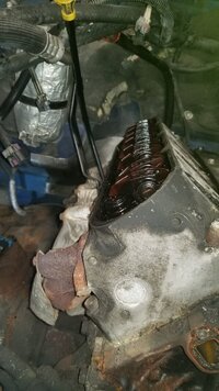
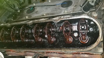
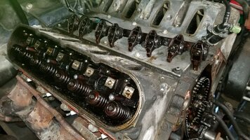
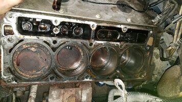
So... with all of that said... let's get started tearing this beastie apart!

(to be continued... )
 

mrrsm

Lifetime VIP Donor
Supporting Donor
Member
Oct 22, 2015
7,619
Tampa Bay Area
If you decide to re-locate the Knock Sensors... Look into the Clearance Issues for the Header Installation... especially if long Tubes are your Choice. What an Awesome Truck, Brother!
 

Reprise

Original poster
Lifetime VIP Donor
Supporting Donor
Member
Jul 22, 2015
2,724
TY, @MRRSM ! Appreciate the kind words, re: the truck. Still lots of work to do.

At this point, I doubt I'm doing headers... here's why...
- While I'm exempt from emissions testing with this truck, due to the 8600lb GVWR (amazing, in IL), and could delete cats / O2 sensors... I'd rather not do that.

- My intent is to enhance midrange / upper RPM HP & torque, where possible, for towing at elevation. 'Shortys' won't be much improvement over the OEM manifolds, and as for long tubes... well, there's the cats to deal with, that I'd like to keep.

- I don't want to make the exhaust drone while driving on the interstate. That's why I took off the Flowmaster (and while I did lose a little bit of responsiveness afterward, as measured by the 'butt dyno', I didn't regret going back to stock).

- If I do a turbo down the line, I'll have to rework the exhaust. Until I decide, I don't want to spend the time / $$$ to do it twice.

TL; DR - we'll see, but for now, I'm hanging on to the stock exhaust.

Spent the afternoon degreasing a set of valve covers and a front crank cover I picked up, thinking I was going to paint them (and wanted to get that done in the garage before putting the truck in). Then I ran across the option of powder coating, and requested a couple of quotes to have it done. So I may not be painting those parts, after all.
 
  • Like
Reactions: Mooseman and mrrsm

mrrsm

Lifetime VIP Donor
Supporting Donor
Member
Oct 22, 2015
7,619
Tampa Bay Area
FWIW... The inexpensive POR-15 "Starter Kit" in either Gloss Jet Black or what looks like the Red-Orange color of the paint on Jay Leno's Maclaren MP412C for contrast vs. the Blue Paint on your Truck would be PERFECT. This Stuff in either color would give you a durable, attractive finish on those Aluminum Valve Covers and other Cast Iron Suspension, Brake Parts and Frame Areas, too:


POR15STARTERKIT.jpg
MP412CREDORANGEPAINT.jpg
 
Last edited:

Reprise

Original poster
Lifetime VIP Donor
Supporting Donor
Member
Jul 22, 2015
2,724
Sometimes I recognize parts I'll need ahead of time, or at a certain point, and buy them beforehand. Or I find a good deal, or they'll save me time, etc. Sometimes all of these things. Such is the case with today's update.

With the amount of room I have to work in, any painting I'd have to do would need to be before the truck went in the garage. Since I wanted to dress up the engine a bit (nothing really fancy), I picked up a set of spare valve covers and a spare timing cover. I think I got these for $25 for all three via CL.

I didn't just want the valve covers painted -- I wanted a 'crinkle' (or 'wrinkled') finish. As it turns out, VHT makes some paint that is supposed to do exactly that, although colors are limited. So I picked up a couple of cans of that, along with some VHT primer. A couple of shots...

ValveTimingCoversCleaned.jpg
ValveTimingCoversPrimered.jpg
ValveTimingCoversPainted.jpg

The observant reader will note that I left the timing cover seal in place. Popping it out after the paint dried produced this nice-looking result:

TimingCoverPost.jpg

To activate the wrinkle/crinkle, VHT specifies 200 deg F for 1hr. Since I didn't want to potentially ruin my household range, I broke out the heat gun. However, all I did was bubble the paint off in the spot where I tried it (the paint is rated to 500F 'intermittent', so I guess they want the heat to be exactly (?) 200F. For now, we'll put these aside, as we're not going to need them for a bit. If anyone's used their household oven for VHT-style paint, and didn't ruin their oven, let me know. I still have time... lol. Otherwise, they'll get their 'curing' after they're installed on engine.


When I first started imagining this project, I always envisioned removing the heads & replacing the lifters when the new cam went in. After calculating what it would cost to recondition the heads (and potential extra costs of acquiring a new one if a crack was found, I decided to pick up an already reconditioned set, to save time / effort (also, '317' castings are supposedly known for developing cracks; you find out via pressure testing the head). Found a nice set of 317s ready-to-go; I think I picked these up for $225 on CL a little over six months ago. I double-bagged them and put them away; when I brought them out, they looked like this:

NewHeadsPre.jpg

Yeah, that's rust on those springs / retainers. So, the lesson for all is... if you're going to store heads, coat them with something so they don't rust!

In my case, I wasn't keeping the springs anyway, so I stripped them out, gave the heads some additional cleaning, and replaced the springs with these...

NewHeadsPost.jpg

No, those aren't blue to match my truck... they're GM LS6 springs, colloquially known as 'blue beehives'. The retainers / locks are the matching LS6 components. About $80 for the springs, close to the same for the retainers (they're titanium, IIRC), and the locks were $40 (? - not sure, but I'll look it up). Add $17 for a spring compressor (a cheapie, but worked a treat) to swap everything out with, and another $17 for a set of digital calipers to take some measurements with (I'll get into this, if people are interested, although I didn't take pics of me actually taking the measurements).

Why'd I choose these springs? Because they're a very cost-effective (& popular) choice for cams up to .550 in. lift. The stock-style springs wouldn't handle that amount of lift, plus they had 230K on them (you'll 'hear' me saying that a few times during this build). I knew nothing about the springs the new heads came with, so didn't plan on using them. The heads came with new seats / seals already installed; valves are stock LS (no fancy sodium-filled, etc.)

Before I started the project, I had gotten a copy of this book (available via Amazon; I got the Kindle version for $14 (had to look it up to get the pic, so here):

1585504173788.png

I find this book pretty useful. While I'm not rebuilding the short block / rotating assy at this point, I may at a later time. I do refer to it often.

That brings me to why I selected another set of 'stock' 317s, vs. going with the 'hot' 799s / 243s...

I did consider heads with smaller combustion chambers. But after speaking with a local machine shop resource, I decided to keep with the 317s, and not have them worked further (e.g.; porting). There's a couple of reasons behind that.
One is my intended use (towing / torque, not max HP / racing).
The other is a desire to be able to use crap gas. Out west, as you get into high elevations, octane is lowered -- the 89 RON that I get at my local gas station here in IL becomes 86-87 RON (as labeled on the pump) in Montana, for example. E85 is another option that I want to be able to use (as it is higher in octane); you see that used frequently up in the mountain areas, as well.

At 8mpg with the trailer on the back, I'd rather not be stuck buying premium. And with a 26gal tank (only size with a CCSB, in this gen truck), fillups come often, on the road. Cha-ching!

Finally, the low-compression 317s (9.4:1 stock) are considered a great option for boost. While I've always salivated over putting a blower on an engine, it turns out that a turbo would be a better option for this truck, and towing, as turbo-equipped vehicles do better with less available air than a supercharger. So, you could say, I'm planning ahead a little bit. If I do it as a 'stage 2' project, I won't be going crazy with the boost - most likely sub-20lb. But that's a ways down the road. And I need to edumacate myself on turbo building / tuning, first.

And that's today's update. Questions / comments, as always, are welcome.
Also, while I'm listing pricing here, it's not intended as a 'brag'... only to indicate what this costs me, in case someone else is looking at doing it. If I swung a really good deal on something, I'll indicate same. I do try and look for best deal available (from reliable sellers).
If you don't like seeing the running costs, let me know (actually, let us know if you do, as well).

So far... (I'll try and get this into a spreadsheet format later).
All costs in USD, unless indicated, but DO include shipping
Labor costs are not included, and you should not assume I complete anything at 'book rate'. If I could, I'd be a pro.

Timing / Valve covers - $25
Paint - $30
New 317 heads - $225 (deal - roughly $100 under similar; twice that if I rebuilt mine)
LS6 springs/keepers/locks - $208
Tools (as above) - $34

Total so far: $ 522.00

Next up: I replace a rear O2 sensor (not part of build, but want to do it before disconnecting exhaust manifolds). I'm not going to document changing this out; just making a note of what I'll be doing before picking this back up in earnest (with parts disassembly)
 
Last edited:

Reprise

Original poster
Lifetime VIP Donor
Supporting Donor
Member
Jul 22, 2015
2,724
@Beacon - No 220VAC. And even if I did, no room to put in a range. Can barely fit the truck in!

Here in the Land of Lincoln, a majority of us have basements, but the energy source of choice for cooking & heating water is natural gas, not electricity. As a side note, we have the most (?) nuclear plants of any state, but pay a rather expensive KwH rate, 'cos it cost lots of coin to build those plants in the '70s & '80s. (That reminds me to check on when those plants are due to start coming up for retirement.)

TL; DR - Appreciate the idea, but not feasible for a couple of reasons.
 
Last edited:

Reprise

Original poster
Lifetime VIP Donor
Supporting Donor
Member
Jul 22, 2015
2,724
At our last update, we went over the heads and springs that I chose for the build.

I also replaced the O2 sensor I mentioned last time. That actually was fairly easy, once I remembered that I wanted to replace the primary, not the secondary (which uses a different harness). Bottom line, it's in.


Today's update will concern disassembly (of a lot of items) :smile: This is a long post, as a result.
(so long, actually, that I had to split it into two, as there's a 10,000 character limit per post!)

I'm not going to explain how to remove a radiator, a valve cover, or a water pump. There are other ways to get that info, and some of you are very familiar with those things, anyway.

I wanted to remove the fenders, and have access to both sides of the engine. But I'd have to pull the hood to do that, and I'd also have to remove all of the front end parts up to the timing cover, anyway. So... I took the majority of the front off the truck. The bonus is that after all of this stuff is out, there's a lot of room to stand in the front (on the frame crossbar, if needed), and just reach right to the back of the engine, as needed. Of the three times I've removed the intake from this particular truck, this one was the easiest. Even disconnecting the fuel lines was easier than normal.

Some assorted notes on disassembly...
- Doing something like this *requires* bagging and tagging bolts, screws, clips, etc. There's just no way around it, as there's too many parts to keep track of & remember.
Get some sandwich bags, and some labels. Tip: Just put the label inside the bag - no need to peel / stick, and no worries about the label getting damaged / lost.

BagNTag.jpg

The bags (along with some zip ties) also are a nice way to protect all of the cooler, fuel, etc., lines that are still in the truck from getting contaminated / leaking fluids.

I figured out by depressing the Schrader valves that there was no refrigerant in the system. So I disconnected the condenser, rather than twist / kink the metal lines further.
The seals tend to become brittle & leak refrigerant, so I'll pick up a kit to replace all of them when I'm putting everything together. And I'll put a vacuum pump on the system afterward, to test things out.

Taking out the fender liners gives additional access through the side, which is a great thing to have - not only for spark plugs and boots, and exhaust manifold bolts, but for the lower head bolts, as well.
My p/s liner was cut / damaged, anyway, so ripping out the old one was a no-brainer. I had put a new liner on the d/s a few months back. Ripping it out again for access, I finally figured out where my P/S fluid has been leaking from - the hydroboost module (from the weep hole) - turns out it's a fairly common thing, as they sell seal kits for it. So I ordered one up today and should have it by the middle of next week.

When I got the truck, the front bumper cover (for a C3 Denali) was held on with only 4 of the 8 or so bolts it came with from the factory. So it was pretty easy to remove the OEM cover that I had put back on the truck.

I was able to get the fan / clutch off without air tools... leave the serpentine connected, and put a cold chisel on the left side of the nut (as you face the front of the engine). A few blows will break it loose (and since the truck looks to have a recent (?) water pump, I'm not going to pretend that if it were the original WP on there for 17 years, that I'd have had as easy a time. Still, not firing up the noisy air compressor was fine with me.)

When you remove the WP, be prepared for about 1/2 - 3/4 of a gallon of additional coolant to come out. So have a pan under the truck, ready to go. If your pan is small, only loosen one side of the pump at a time; it takes awhile for the coolant to finish draining from the top of the motor. Just like it took to finish draining from the radiator, when you opened that up.
One other thing about draining coolant - even though GM was to have discontinued putting the petcocks in radiators from MY '03 onward - I found out after the radiator was out that it actually had a petcock, all the way on the d/s of the radiator. So check, b/c you never know. Mine was missing the rubber hose that tucks up into the fan shroud area -- but I did have the petcock. Wish I knew ahead of time!


The crank bolt / dampener: This was a bit of a challenge. Ok - it was a b!tch...

I had purchased this tool ahead of time, in hopes it would easily remove the bolt. It *did* remove the bolt - but it needed some help from me, first. Outside of that, it is a useful tool, and has power -- but it is heavy, and not terribly well-balanced. It's also a "all or nothing" w/ regard to the trigger - no variability to the power / speed. Don't try to attach a universal joint anywhere in the socket chain on it, as the torque will send it flying.

1587775919593.png

First off... Immobilize the crank, because even with the serpentine belt on, and with sealed heads maintaining compression, the crank will just turn when you put a breaker bar on it. 24mm socket, btw.
Flexplate_Immobilizer.jpg


FPI_Tool_Installed.jpg
I had planned ahead and picked one of these up from Amazon for about $20. It was pretty easy to drop the starter (hey - it ain't a TB / Envoy!) and attach this tool to lock the flexplate in place. Bolts are also supplied (but they're a different size head than the OEM starter bolts. Mildly aggravating to swap sockets, but I managed.) LOL The worst part of dropping the starter was figuring out the sizes of the 8 and 10mm nuts to disconnect from the truck wiring.

With the flexplate immobilized... you, the impact, and your breaker bar can get to work.

First, I tried the gun. HF may advertise 1050 ft/lb of torque, but it didn't look to budge the bolt. Time to get out the breaker bar, with cheater pipe.
Unfortunately, I'm not as strong as I used to be, and I didn't think I moved the bolt. Back to the gun. On a hunch, I reversed direction - and it moved slightly in the tightening direction. So I rocked it back and forth for a bit. Didn't seem to move further. Back to the breaker / cheater. No, I didn't get any stronger. Hooked the gun up again, and it moved a little more when I alternated directions. Now I knew I'd be able to eventually get it off.
Took about 5 minutes, back and forth. But it finally let go, and the 24mm bolt spun right out. Looked like it came out very nicely, too.


On to the dampener...

I knew that the dampener had 3 'slots' or 'indentations' on the back side, in the center hub. That's where I attached my 3-jaw pullers. Which either didn't fit, or one of the jaws was out of commission (cheap HF crap), or the forcing screw wasn't long enough, or the cone at the end wasn't wide enough (I did slightly gouge the crank snout, just inside the outer surface). Off to rent a 'Chrysler' puller from AAP.

The Chrysler-specific tool was made because their balancers are the same as GM's - there are no threaded holes in the balancer to attach a 'duckfoot' puller to.
The nice thing is, they are supposed to be 'just right' to pull LS balancers, too. In those slots I mentioned earlier.
GM also molded 3 'tabs' on the legs of the balancer; that's how the J-tool connects. But we won't reference that tool, because it's expensive, and you don't need it.

Got the balancer puller kit home, and as it turns out... the forcing screw on that was too short, as well. The kit has two 'rods' that are to be inserted into the crank opening, but they're not long enough.
Now I'm getting p!ssed, because I've wasted a lot of time if I can't get that balancer off. But I eventually got it off. Here's how...

- Put some oil on the outer lip of the crank snout
- Get a large 3-jaw puller (I used an 8"), and a 22mm socket (short is fine)
- Set up the puller so that each jaw rests against the back side of those 'tabs' that I mentioned. This means the legs / jaws of the puller will need to twist a bit, to lock in. Place the hex end of the socket against the crank snout, and turn the forcing screw so that the conical tip is resting against the square 'drive' end of the socket. Then start turning the forcing screw.

What happens in this arrangement is that the forcing screw will not reach the end of its travel, resting against the socket. But the jaws will start drawing off the balancer.
Note -- you will likely need an impact wrench to turn the forcing screw after a few turns. Or, you better be REALLY strong.
After several seconds (depending on how slow and careful you are, and how many times you stop and check alignment, etc.) -- the balancer will be drawn off the crank. Halleh-frickin'-LU-jah!

Now the timing cover can be removed. The bolts are all the same length -- even the two on the lower side, underneath the cover.

I removed the timing cover now *just* to check if someone had already put a cam in -- this engine pulls stronger than the last 6.0 I had (I actually owned both trucks at once, so I knew the difference). As it turns out -- this engine looks stock -- no upgrades, just a lot of varnish & sludge (230K, remember?) So I put the timing cover back on, and went back up to the top of the engine, as the rocker arms have to be loosened, at a minimum, before messing with the cam gear / bolts. Do NOT touch those cam gear bolt(s) yet.

Now go and remove whatever you were using to immobilize the flexplate, so that the crank can turn again. Then thread the old crank bolt back in, by *hand*, until it seats. Get your 24mm socket and breaker bar handy, you'll be using them in a few minutes.

(to be cont'd... )
 

Attachments

  • IntakeRemoved.jpg
    IntakeRemoved.jpg
    399.1 KB · Views: 8
  • Bank2Valvetrain.jpg
    Bank2Valvetrain.jpg
    351.7 KB · Views: 8
  • Bank2_Closeup.jpg
    Bank2_Closeup.jpg
    360.2 KB · Views: 9
  • RockerTrayOut.jpg
    RockerTrayOut.jpg
    372.9 KB · Views: 10
  • Bank1_HeadRemoved.jpg
    Bank1_HeadRemoved.jpg
    526.6 KB · Views: 10

Reprise

Original poster
Lifetime VIP Donor
Supporting Donor
Member
Jul 22, 2015
2,724
1587778824372.png

Here, you see the top of the motor with the intake removed. Unless you've recently had your intake off, say, to replace your knock sensors (Gen III engine), I can guarantee you that the surface area will NOT look even this 'clean'. I had done mine recently.

If you have original knock sensors / harness, now's the time to order replacements. You can see my sensor harness is new, as it was replaced just a few weeks earlier, along with the knock sensors. If your harness is old, the connectors under those rubber covers are going to be very brittle, and the retaining tabs *will* break off (you squeeze them to release from the sensor, once you've created some slack between the rubber covers you pried off and the connector).

Thankfully, the harness isn't that expensive. If you have a Gen IV engine, or want to relocate your Gen III sensors to the Gen IV locations on the side of the engine block, then don't worry about breaking the sensor connectors, and you can probably leave those sensors where they are, unless they're new. In which case, you already know you need a 22mm deep socket to get them out.

Leave the valley cover in place, for now; it'll help keep the internals cleaner. If you have a Gen IV engine with cylinder deactivation and want to remove it, get your parts ordered now (usually as a kit.)

Remove the boots from the spark plugs. You can leave the end that attaches to the coils in place, if you like. You don't have to remove the spark plugs (I didn't), but you may encounter some clearance issues removing the head bolts later on, if you don't. If you remove them, label which cylinder each plug was in, so you can evaluate the condition of the plugs / cylinders afterward, if any look 'bad'.

The exhaust manifold bolts are 15mm, while the mount for the dipstick tube is 13mm (thanks, GM). If your bolts haven't been recently replaced, like the prior owner did with mine, you're almost certain to break one or more of them off, due to corrosion / heat, over the years. Go ahead and remove those bolts now, because after the valve covers are off, you'll be ready to remove the head bolts & the heads, if you're going the same way I am. The oil dipstick tube will easily (!) pull out of the pan, and it'll be much easier to remove the exhaust manifold, if you pull it.

I was able to get five of the six nuts off the exhaust studs easily with the electric impact. The sixth one (in the least accessible place, naturally) came most of the way out, but the stud spins freely. I'll worry about that after I get the heads off. I know I can get in with a hacksaw & remove it, no problem.


On to the valve covers, so we can loosen those rocker arms, pull the pushrods out, and finally be able to spin the cam and push the lifters up into their trays. I'm removing my heads, as I'm putting new lifters in, as well as new heads. But the rocker arms still have to be loosened up and pushrods pulled, even if you aren't going to replace your lifters (which I don't recommend, if you have a higher mileage engine like I do).

While some people advise that the coil pack frame can be left in place (after you disconnect the wire harness from it), and removed with the valve cover all in one piece, you're really not going to be able to do that until all four valve cover bolts are removed - and the two inner ones are under the coil framing. So get started removing the five threaded studs that hold the coil frames onto the valve cover (10mm, and does not have to be a 'deep'). You *can* leave one at the very end connected, and swing the frame upward, once you break the torque on it -- then remove the valve cover bolts. Once that's done, swing the frame back, lift off the cover and put it aside. Tip: Label which bank each coil pack assembly was on; it may be helpful if you have to trace any issues later on, if you reinstall the coil packs on the sides they were originally on. That's assuming you're not putting new coil packs in (I'm not).


And now, feast your eyes on that valvetrain... mmm--Mmm! That's what I'm talkin' bout...
1587778861602.png


The rockers can be removed in one group, via a bar that holds them. However, don't just put your 8mm socket on the rocker hold down screws and start turning freely, yet.
First, make sure that the rockers you're going to loosen aren't fully compressing the springs. If you need to, turn the crank (always clockwise) to get the rockers you want to loosen off the compression stroke. Then loosen the rocker arms. That way, you won't strip the threads (they're aluminum, remember).
You'll actually be able to hear the air escape from the cylinders as you turn the crank.
You don't have to fully remove the rocker to get it off the pushrod. If you're removing the pushrod, label them as to cylinder, whether intake or exhaust, and identify which end is top. Why do this? Because you want to examine for wear - and also to see if any are bent. Bent stock pushrods are a fact of life with the LS motor. You can check them by rolling along a flat surface. But clean them first.

Fully loosen the bolts from the rocker arms (8mm). If you leave them in the rocker arm, you can lift them all out at once with the bar they sit on. Convenient.
1587778903238.png


I put the motor at TDC before removing the cam sprocket bolts & the sprocket.

I had the idea of leaving the pushrods in, as I spun the cam - that way, I could tell if any weren't at the top of their travel, and didn't get captured in the lifter tray.
However, this didn't work too well. I pushed the pushrods down until they stopped their travel, then put a WP bolt in the cam and started turning.
About 3 or so turns later, the cam stopped moving. I knew enough not to force it, and went on to pull one of the heads.

The five top head bolts (10mm) get pulled first. These can actually be reused, if desired. They're torqued lightly enough that a 1/4" ratchet will loosen them up.

When you loosen the 10 main head bolts, try and work from outside toward the center, if you can. Also, break the torque on the bolts by hand -- that way, you'll be able to tell if any of them look like they will cause an issue. I broke them in reverse order, and gave each 4 x 90 degree turns to start, before fully removing any. I figured that way, the clamping would be released fairly evenly (although the LS book I mentioned earlier didn't specify this). Get a drain pan ready, because coolant will start draining out of the back side of the head / block, once you back the bolts out 5-6 turns or so.

If you have a 2003-2004 engine, check the length of the two upper bolts, relative to the eight others - if they're shorter, make sure to replace with the same length bolts. If you buy a set of bolts, they're always grouped by '98-'03 and '04-onward. But consider this... there have been people with 2004 trucks that had the *shorter* bolts. And some 2003 trucks had the *longer* ones. Chalk that up to GM's parts bins (hopefully, the right bolts got installed into the right blocks, back in the day). My 2003 had the shorter ones, btw.

Also, with regard to the bolts, I was originally going to replace the head bolts with a new set of GM torque-to-yield (stock). However, some of the bolt locations make it a bit difficult to reach, with the engine in-car. Especially in the very back of the motor. I know it will be worse when installing them, given the TTY method. Given this, I'm seriously considering a set of ARP bolts now, as they don't require a TTY sequence. They're also reusable. But they're also hella expensive. I had already decided I'd use an ARP crank bolt; now I get to decide if I want to try TTY bolts or not.

For those of you who ask "why not put in a stud kit" ? Because I'm worried about clearance to put the head on with a stud kit, with the block in the truck. Besides, I'm not racing, just towing :biggrin:

With the last of the bolts out, you can lift off the head. I was pleased to see that I could still see the honing marks (crosshatch) on the cylinders on the side I pulled. 230,000 miles, and the cylinders were pretty much as they left the factory. That was nice to see.

There will be coolant in the three rearward cylinders on bank 1, if you put the crank at TDC. Get that out now, and dry the cylinders. I put some WD-40 in mine, to keep moisture from starting to rust the cylinder walls (that's what that little white spot is, on #5, below).

1587778944212.png

Finally, I got to pull the lifter trays, to see if the lifters were successfully captured back into the trays, when I spun the cam.
NONE OF THEM WERE.
Why do I capitalize that? Because if you are going to install a cam in a high-mileage motor, without replacing the lifters, and expecting to push them back up into their trays, then inserting the rods in the upper oiling passage in the block, to retain them as you remove the cam -- you may find that they weren't captured, at all (when one or more of the lifters makes a 'clink' sound as it falls into the rotating assembly).

In other words... if I'm personally putting a cam into a motor with a lot of mileage - I'm going to pull the heads, myself. Period. I am *so* glad I didn't try pulling the cam after spinning it.

I was able to get one of the lifters out with a magnetic tool (you can see it sitting on the valley cover, above). So I'm not too worried about the lifters dropping into the rotating assy. But I know that one or more of them is caught between the cam lobes and the lifter bore.

Stopping for today, and will pull the other head / all the lifters out tomorrow, then remove the cam. But I've got enough of it apart to stop here, and update the thread.

(out of room here; will update cost totals at next update)
 
  • Like
Reactions: BrianF and Mooseman

Reprise

Original poster
Lifetime VIP Donor
Supporting Donor
Member
Jul 22, 2015
2,724
Putting in one more update... I had to reattach pics to the 2nd post, and they display in 'miniature'.

If there's something I wrote about that you'd like to see a picture included on (besides the above ones), let me know and I'll see what I can do about adding it (full size, for visibility). However, I'm up against the 10K text limits, so if you need further explanation of something (as if!), that'll have to be via a new post. Thx.

Since I made a 3rd post, I'll put the cost update, here...

Next up - put in another parts order and clean, clean, clean, while I'm waiting for the parts.
Tune in next time, when we get to see Reprise use a Roloc wheel!

Cost update:

Parts: None

Tools:
Tool to immobilize flexplate: $22
HF Electric impact gun: $80
Ares dampener puller tool: $35 (didn't use, but stuck w/ the purchase)

Subtotal: $137

Running total: $659
 
  • Like
Reactions: BrianF and Mooseman

Reprise

Original poster
Lifetime VIP Donor
Supporting Donor
Member
Jul 22, 2015
2,724
Yes, I made it back from Mordor - alive! LOL

I'll spare the suspense... I've finished the mechanicals, started up the truck, and broken in the cam (more on this later). It's Alive!

The good thing is that I kept notes as I worked on this, and can now update the thread. While I could post all the updates one after another, I decided awhile back that I'd post an update, wait a couple of days for any comments / questions, and then post another update. That way, no one has to say "back in post 1,104, you said... " :bonk:

So... without further ado, here's the 'beginning of the rest of the updates'...
 

Reprise

Original poster
Lifetime VIP Donor
Supporting Donor
Member
Jul 22, 2015
2,724
Last update, I mentioned using Roloc wheels (also known as 'whizzer wheels').
Today, I'm back to say...
Do NOT use a Roloc on a 'critical sealing' surface (e.g.; a block deck or head surface). Even a white or yellow (the two least abrasive, respectively). Even on cast iron.
Besides the distinct possibility of creating low spots on those surfaces, a Roloc will throw off fine aluminum oxide particles as a result of using it. If these find their way into the engine, they can ruin a bearing in as little as 1500 miles (per GM bulletin).

Are there uses for a Roloc in our project? Yes, and we'll get to those later.


Cam removal:

I had some trouble removing the camshaft, but was able to get it out by reattaching the cam sprocket and chain (using two water pump bolts in lieu of the cam retainer bolts), then using the mechanical advantage of the engine to turn the crank with one hand, while at the same time spinning the cam out with the other. You'll only be able to get 2-3 inches of the cam out before the sprocket & chain bind on / slip off the crank sprocket, but that will be enough. If you find that you can't pull your cam out, give this a try. I've not seen it described elsewhere.

0426_cam01.jpg
(stock cam removed; lobes were in good shape, as were the rollers on the lifters)

With the cam and valley cover off, I was able to backlight the cam bearing area via the valley, and I could see all the way to the back cover. Frankly, it looked a mess - just like the front cover did, when I pulled it off. I seriously considered taking the block out of the truck and just doing a full rebuild on it. But I knew that would add money and time to the build, and I had faith that the bottom end was good.

20200426_175605.jpg
(no, this isn't a scene from the 'Alien' movies; that's the coked on oil on the inside back cover (flexplate side)

So... I pulled the oil pan, pump pickup tube, and windage tray. Except for the crank side of the windage tray, those had a good amount of sludge / coking on them, too. But the rotating assembly / block walls / back side of the cylinder bores looked good - just a lot of varnished surfaces. Seeing that, and doing a little sleuthing on the condition of the cam bearings, I decided not to remove the block or break it down further. I also solicited advice from some of our members here, who agreed with me. When you think about it, it makes sense that the rotating assy wouldn't have much in the way of sludge / gunk - after all, it's constantly rotating 1000's of times / minute!

20200504_155049.jpg
(underside of rotating assy; crank snout on LH side; RH side shows the 24x reluctor. Again - not bad for 250K mi, IMHO)

Motor Mounts

With the pan off, and the motor down to the block & rotating assy, I figured it only made sense to change out the motor mounts, so I ordered up a set. Turns out that the one on the passenger side had lost the top part of the rubber mount -- so when I got it out, the top of the mount moved freely within the lower part. So they needed to be replaced, anyway.

Tips on replacement:
The frame crossmember is held on with four 19mm bolts. GM uses yellow locker on the bolts. So they'll be in there, tight.
You'll need to remove the aircon compressor bracket (meaning that you'll need to take out the compressor itself, as it hides at least one of the bracket bolts.
There's one bracket bolt (bottom rear) that is difficult to remove, due to interference. I had to take a 15mm open-end and flip the thing every 1/16th of a turn (kinda like taking out a P/S line).
(note: I learned at reassembly time that it was much easier to get to this (?) bolt, from the top end, using a regular socket / ratchet. So go at it from the top)

You'll also want to remove the last bolt on the other side holding the P/S pump to the block. It's a 15mm, too.

Break the torque of all three mount-to-frame bolts first, as well as the mount-to-block bolts (which are only about 1.5" long). It's OK to remove the two bottom bolts on the block side, if you're worried about the jack blocking them in the next step. All are 15mm. You'll want a breaker bar or impact for the frame bolts, for sure. The block side bolts loosen easily.

If you have the oil pan off, jack up one side of the engine by the block side rail only. Don't place a board across the two sides (especially if you can't get the crank fillets / counterweights / rod ends below the crank bearing caps -- you'll stress the crank / assembly, if you do). And don't place boards near the back of the motor, so that you don't stress the rear cover / crank seal / etc., etc.
I cut boards 12" long, and placed them on one side at a time, then jacked up enough to take the weight off the mount, removing the remainder of the bolts.
When all bolts are out, jack the side up about 2" further, so that you can get the mount out. It'll come out easier moving it backward (toward the trans).
With the old mount out, make sure the holes on the new one line up properly, using the old mount as a template. There is no 'left' or 'right', btw.

20200511_121338.jpg
(raising the block by the side rail - no stress on the rotating assy, this way)

Important -- when fastening the new mount, fasten all four mount-to-block bolts FIRST, before the mount-to-frame bolts. You don't need to torque them down -- just get them attached, first. You'll never line up the mount if you do it the other way around. It took me about 2hrs to get the first mount replaced, and 20min to do the second one, once I figured out the attachment order. Also, if you look at the holes on the motor mount, you see that the ones for the larger bolts are elongated, while the ones for the block side are round and sized with the bolt.

Once you've got all the bolts started, go ahead and drop the jack. If you want to do the lower block bolts from underneath, it's OK. Snugging up one of the block bolts will hold it fine while you tighten the other three.
The smaller block bolts torque to 37 ft-lb, tighten the larger frame bolts to 55 ft-lb. Threadlocker isn't spec'd; I didn't see / use any.

With new mounts in, go ahead and reattach the pan for now, just to keep the bottom end 'safe'. Two bolts will suffice.

While you're there, note the locations of the crank position sensor (passenger side, near the starter), the oil level sensor (same, in the oil pan), and the two coolant drain bolts in the back (driver's side is a 17mm hex, on the angled (cylinder) side; p/s is an 8mm hex that's mounted horizontally (pointing straight down). I ordered up new ones for all of these except the oil level sensor in the pan. Also note the cam position sensor at the rear of the block, and the oil pressure sensor (which requires a 1 1/6 thinwall socket; I picked one up for $7 and change from Amazon, as it's nearly impossible to get out otherwise with the engine in-vehicle, given the short block to firewall clearance.)

If you want the balance of the coolant out of the block (there's still about 2 US qts), remove these drain bolts.
Note: The larger bolt can be loosened enough to control the draining of the coolant. The smaller bolt cannot - it'll all pour out suddenly. Have your pan ready, and your safety glasses on!

You can reuse these bolts if they're in good shape, but be sure to use a PTFE-based sealant on the bolts. I wouldn't use the white tape -- if it unravels inside the block, it can block oil galleys, coolant passages, or find its way into your oil pan (if you're lucky, or somewhere else, if you're not). New ones come with sealant on the threads. I got a new 17mm, which are available in brass. I could only find the 8mm in steel (they're the same size / type as the oil galley bolts, btw.)

With the coolant out, you can go back up top. There's still some coolant in the bolt holes in the block (they're not exposed to the coolant passages, but some spilled in when you removed the heads, just as it did with the rear cylinders.)

Make SURE to blow out the bolt holes of all coolant, especially in the rear locations (no penalty to do all of them, and I heard / saw fluid jump out of the front ones too, so do them all).
If you don't remove the coolant from these bolt holes, you will create hydraulic pressure as a byproduct of tightening the head bolts, and that can crack the block (you won't see it, except for the two rear bolts, and then only if you have the rear cover off). So make sure you do this, if you have the block in the vehicle. There WILL be coolant in those holes!

With that done, we can turn to prepping the block surfaces for gaskets. I like to work top to bottom, and outside to inside. That lessens the chances of getting dirt / grease / gasket scrapings in the block, and on the surfaces you've already cleaned.

Next up: Block surface prep (it'll be a small update, as it's really the end of this one that I couldn't fit)
 

Attachments

  • 1598666453275.png
    1598666453275.png
    383.1 KB · Views: 3
Last edited:
  • Like
Reactions: BrianF and Beacon

Mooseman

Moderator
Dec 4, 2011
25,224
Ottawa, ON
Hey man, haven't seen you in a dog's age. Welcome back! You should change your name from Reprise to Revenant, :biggrin:

Here's a picture of it (mine is 5/8" wide; they also sell them in a 1 1/2" and 2" width,

Stealthy. It's so good, you can't even see it. :biggrin: There was some talk about carbide scrapers in the Tool Talk or the Mail thread. Looks interesting however I can't justify paying $50CAD for a scraper for the few times I would use it.

Years ago, manuals would always warn against using any mechanical gasket removal like sanding or Scotch Brite disks for the same reasons you enumerated so generally don't use anything except scrapers. Maybe the only exception is on the diff cover where stubborn gasket glue was used and I'm using RTV.

So have you determined was causes the cam hangup?
 
  • Like
Reactions: mrrsm

mrrsm

Lifetime VIP Donor
Supporting Donor
Member
Oct 22, 2015
7,619
Tampa Bay Area
Welcome Back, Brother!

In Post #3, You mentioned “...spending all day de-greasing the Valve Covers…” which leads me to bring up a thread from last month that @m.mcmillen made mention of as being THE solution to the mysterious problem of having, “Excessive Oil Consumption in the 5.3L Engine…”.

He explained that the main culprit turned out to be the Poor Design of the GM LS Engine Driver’s Side Engine Head Valve Cover. FWIW… His information lead those interested among us to seek out and obtain the GM OEM Updated Design for the LS Engine Left Bank Valve Cover here:

Genuine GM 12570427 Valve Rocker Arm Cover:

https://www.amazon.com/dp/B00F66SLG8/?tag=gmtnation-20

I know you’ve already endured the task of painting the Old Valve Covers Blue but considering how much Carbon and Thick Oil Build Up your High Mileage Project Engine Head Valve Train displayed in your tear down images, having this New Cover Design on your “Left Flank” would be yet another way to help the newly Re-Built Engine avoid any Old, Bad (Oil Drinking) Habits. :>)

GMLSNEWDESIGNVALVECOVER1.jpgGMLSNEWDESIGNVALVECOVER2.jpgGMLSNEWDESIGNVALVECOVER3.jpg
 

TollKeeper

Supporting Donor
Member
Dec 3, 2011
8,039
Brighton, CO
Did you come up with a name yet?
 

Reprise

Original poster
Lifetime VIP Donor
Supporting Donor
Member
Jul 22, 2015
2,724
Stealthy. It's so good, you can't even see it. :biggrin: There was some talk about carbide scrapers in the Tool Talk or the Mail thread. Looks interesting however I can't justify paying $50CAD for a scraper for the few times I would use it.

Years ago, manuals would always warn against using any mechanical gasket removal like sanding or Scotch Brite disks for the same reasons you enumerated so generally don't use anything except scrapers. Maybe the only exception is on the diff cover where stubborn gasket glue was used and I'm using RTV.

So have you determined was causes the cam hangup?

Ran out of room and had to juggle my text around, but the pic of the 'Super Scraper' is at the end of the post. I got that one based on a couple of machinists posting about using it on head surfaces. Yeah, it's more than I wanted to spend (and, of course, that's the cheapest I could find it), but I *do* see myself using it again. Things like this are why my build costs went 'cha-ching!', in the end.

In Post #3, You mentioned “...spending all day de-greasing the Valve Covers…” which leads me to bring up a thread from last month that @m.mcmillen made mention of as being THE solution to the mysterious problem of having, “Excessive Oil Consumption in the 5.3L Engine…”.

He explained that the main culprit turned out to be the Poor Design of the GM LS Engine Driver’s Side Engine Head Valve Cover. FWIW… His information lead those interested among us to seek out and obtain the GM OEM Updated Design for the LS Engine Left Bank Valve Cover here:

As it turns out, I did implement your solution - I had purchased a second set of valve covers and a front cover from a guy on CL (used, so I had to clean them, but that allowed me to paint them and leave the truck intact (and outside -- it's really cramped with the truck inside the garage).

So, as you referenced, GM redesigned the VC (twice, in fact). I had the original 1st design, which used a PCV valve. Since the later versions did away with the valve, I decided I wasn't going to just plumb up VC to intake, long-term. Stay tuned! 😉


Did you come up with a name yet?

No! And I've put more thought / effort into it than I should've, to this point. One of the issues is that I either want to get a vanity plate incorporating the name, or a mural graphic painted on the tailgate ($$$). The problem with the plate is that I'm limited to 6-7 letters (and no numbers, as my state has this registered as a 'B' (Class 2) truck. Everything I want is pretty much taken, off-limits, etc. Besides the cost of the tailgate mural (are those passé, now?), it's something that would be done after the rest of the truck is resprayed (and I'm not ready to do that, yet)
But - if you've got ideas, I'm more than willing to entertain them - pass them along!
 
  • Like
Reactions: Matt and Mooseman

Reprise

Original poster
Lifetime VIP Donor
Supporting Donor
Member
Jul 22, 2015
2,724
Head and block prep:

20200426_180115.jpg
(Here's a good 'pre' cleaning shot of Bank 2 (PS). Here you can see the honing marks / crosshatch
still present on the cylinder walls. I got lucky on the carbon 'ring' at the top ridge - was able to just wipe it off with a bit of effort, no scraping. You also see the carbon build up on the piston heads (again, fairly minor, compared with some other engines. All in all, not bad for it's age / mileage
)

If you've never used a carbide scraper before, you're in for a treat. The thing requires almost no pressure, and works well by 'pulling' it back, instead of 'pushing' it forward (easier to control). You *can* push it, but you can get most of your surface clean by just lightly dragging the blade back. Save the 'pushing' for the last little bits that don't come off. You won't need a ton of pressure in that direction, either. Use brake cleaner or solvent of choice liberally, as needed. Note that you may still see some (gasket) discoloration in areas afterward; this is OK, as long as you've got the surface cleaned properly.

While you want to get the entire surface as clean as possible, the most *critical* areas are the 1/4" or so surrounding each of the cylinders. Use your bare finger to trace along the surface of these, at a minimum, and make sure they're ab-so-LUTE-ly smooth. The more time you spend on prepping this surface, the better seal / result you'll have. If you're reusing your heads, then this applies for that surface, as well (I have newly prepped heads, which saves me a bunch of cleaning / prep.)

I recommend doing this over several sessions, instead of 'all at once'. You'll see places you missed and will need to go over again when you return. Also, look at the surface from different angles; you'll often 'see' something you missed that way, too. Each time you step away / take a break, re-coat the surfaces with WD-40, to guard against rust / oxidation -- especially the cylinder bores.

Do NOT use the scraper inside the cylinders. If you really want to decarbon the pistons, put them at TDC, first. I prepped #2 here to show you what that looks like (I'm not worrying too much about the rest; mine aren't covered with a ton of carbon, which kind of surprised me, given the mileage of the motor).

20200521_174211.jpg
(Still a bit of elbow grease needed; this is about 75% through, I'd say. The top LH corner is where I
originally attempted using the roloc (darker); rest is by hand. One of the new motor mounts is visible; you can see the misshapen cover plate where I tried to beat it into place. The other one,
I got smart and put the block bolts in, first, then the mount to frame bolt, which is correct (last post))


Finally, the 'sheen' of the WD-40 on the block can help you visualize if everything is smooth, as well.

Don't forget the front side of the motor (WP inlet / outlet, front cover gasket surface). Liberally spray WD-40 onto / into these surfaces, too, especially if you've got an iron block.

That's enough for this update. We're now ready to put in the new cam / lifters / heads, which will be our next post. (because you want / need cam & lifters done before the heads - my bad!)

Cost update (rounded up to nearest USD, shipping costs not included):

Parts:
Motor mounts: $26
Cam sensor: $26
Crank sensor: $21
Oil pressure sensor: $33
Oil level sensor: $18
Coolant plugs: $12


Tools:
Scraper: $28
Oil pressure sender socket (Lisle, via Amazon): $7

Subtotal: $171


Running total: $830
 

Reprise

Original poster
Lifetime VIP Donor
Supporting Donor
Member
Jul 22, 2015
2,724
Cam & Lifters

The day before you plan on installing the lifters (if new, which I'd recommend, anyway), clean them with mineral spirits and let them soak in 30W SAE oil overnight. You can throw your timing chain in the soak, too.
There may be some 'oil' on the lifters & cam, but it's not lubrication oil, it's there just for preventing corrosion during storage. That's why you use the mineral spirits to clean both.

LS7_Lifter_Oil_Soak.jpg
LS7-spec lifters (Eaton) in straight 30W. Note the lube orifices pointing upward.

On to the cam. Here she is:

Comp_Cam_Box.jpg
Part of Comp's 'XFI Extreme Truck' series. This one is for the 6.0L, and emphasizes torque.

Originally, I was going to put cam lube on the bearing journals (the larger round sections between the lobes), as well as the lobes. But no one recommended that. Put OIL on the cam journals, and cam lube on the cam lobes.

As I was considering how much of the oil would be scraped off the journals as the rear ones went past all the other cam bearings, I took another wooden dowel, attached a denture brush to it ($1, at the dollar store), and cleaned the bearings one last time, then put assembly oil on the brush and spread it around the bearing surfaces. With the valley backlit, light will shine into the area, and you can see what you're doing.
Maybe it'll help, maybe not. I figured it couldn't hurt, so what the hell...

Cleaning_Cam_Journals.jpg

Now it's time to finish prepping the cam. Clean it with mineral spirits (if you haven't already). I used gloves, although no one said I had to.
Take your cam lube and spread it along the top of one lobe, so you can see how viscous the lube is, if it runs off easily, etc. Go ahead and rub some on the underside of the lobe, but for now, concentrate on the top half. Leave the journals bare for now.
Once the lube is on at least the top of all sixteen lobes, turn the cam over 180 degrees. Now lube the other side of the lobes. After that's done, clean off your hands, and put your assembly oil on the journals. You can leave it off the two front journals for last, if you like.

Cam_Insertion.jpg
Inserting the cam...

Remember that your engine block is canted, if still in-car, but it won't help much to try and keep it at the exact angle while you put the cam in.
Also remember that the journals and bearings are all equally spaced, so if you see the part of the cam you've inserted squarely resting on the front bearing, so are all the others that are in the engine. This gives you a chance to change your grip, as needed. With the journals oiled, the cam should easily slide past each bearing.

Have your water pump bolts ready (to use as 'handles'), but you don't have to have them screwed in at the outset, if you prefer.
Grab the cam in a place where you'll be making minimal contact with the lobe / journal surfaces.
Line up the journal with the bearing, and slide the cam up to & onto the second journal. Don't worry if you 'bump' a lobe edge against the block; as long as you're not forcing the cam in, you'll be ok.
As you go in further, you'll need to lift the cam end as best you can. The worst of the segments is the very last one, as you have little surface left to maneuver the cam. Rotating the cam so that the adjacent lobes can re-center should help. Back the cam up slightly, if needed, so that you're not rubbing the edge / surface of the lobe against the block. If you didn't lube the last journal or two with oil, don't forget to do so, now!

To tell the truth, I forgot to rotate the cam as I put it in, but the only segment I really had any trouble with was the last one. About 7-10 seconds of fiddling, and I got the last one in. Halleluia! Crack open a beverage, and locate your *new* cam retainer plate, as well as your cam position sensor. Note whether you have flush or recessed bolt heads - there are different versions. And if you have a Gen IV motor, those bolts likely have Torx heads (and use a different torque spec)

Lube the retainer plate gasket, the cam thrust bearing (front facing surface behind the retaining bolt(s)), and the area on the retaining plate that comes into contact with the thrust bearing. Thread the bolts on; if you're sure you won't be fiddling with the cam journals any longer, put some blue Loctite on the bolt threads and tighten to spec (18 ft-lb for Gen III 'conventional' head bolts). Also lube the o-ring on the cam position sensor, if you want to install that now, and tighten that to spec. If you have a new oil pressure sensor, now's the time to get that installed, too, while the heads & intake are still off & it's easy to reach BTW, a special (deep) 1 1/16" socket will make quick work of the OPS, and you can get one for $7 and change. Well worth the spend, if you're doing this in-car (no room for a wrench between it and firewall)

Because Comp's cam lube is sticky, but does run off somewhat, I decided to get the lifters in at the same time, so that they were resting on the lobes and preserving some lubricant on those resting areas, as I know it's going to be many days before I'm in a position to start the engine. (little did I know just 'how' many, as it turned out, and that's not good, either)

Take the lifters out of the oil bath and wipe off the bottom roller. Then apply your cam lube to the entire roller surface, and insert into your (new) lifter trays. Note the flattened surface on opposite ends; they only fit in the tray when aligned properly. Don't bother wiping off the oil on the side of the lifter; it'll lubricate the bore when you insert it into the motor. If you want to pre-lube the lifter bores, just in case, that's fine, too.

You'll apply lube to the pushrod ends, so don't worry about putting too much on the plunger end. You don't want to block the oiling hole on the pushrod or the plunger. Per my sources, it does not matter whether the side oiling hole(s) on the lifter is facing toward the engine front or back (yes, I *did* check!)

When you put in the lifters and trays, they'll require a bit of a 'push' to get them fully seated in the block. Don't overtighten the retaining bolt - 88-106 *inch-lb* is all that's needed. I tightened to 100 in-lb.

(edit to add: The lube had dropped off by the next morning (on both the cam and the lifters), so I reapplied to the lifter rollers, and put them in contact with the cam lobes using the end of a pushrod. Each time I did this, I turned the crank / cam one full revolution (back to TDC), to ensure that I didn't cause interference between a lifter and the cam (I did do this when removing the old ones, as I (think) I mentioned in an earlier post). But it seems OK to do it when putting new ones in.

With the cam & lifters in, we'll go back to the cylinder bores, clean them again, and this time, apply some oil to the walls, as you're going to be turning the crank a bit, and once the heads are back on, that will be the end of your access to the cylinder bores. Put cylinder #1 at TDC, where the alignment dot on the crank sprocket is at 12 o'clock. Put the cam sprocket retaining pin at right about 3 o'clock (this will put the cam sprocket alignment mark at '6', which is right where you want it - lined up together with the crank dot). Tip: If the marks are hard to see, you can use a Sharpie 'paint pen' (about $5 at Home Depot) to make the dots 'white', and easier to see - especially the small crank dot.

Lube the back of the cam sprocket where it attaches to the cam, then snug the bolts on and align the timing mark with the crank sprocket mark (classic '6 and 12' positions). If you want to lock your crank / flexplate in position, you can, but it's not absolutely necessary. Remove the cam sprocket & retrieve your NEW timing chain (I'm using a single roller / stock LS6 replacement; if you're doing a double roller, then you'll have some extra different steps, which I won't go into here.

Drape the chain on the cam sprocket, and bring it over to the motor. While holding the cam sprocket / chain in one hand, use the other to get the bottom of the chain links on the crank sprocket, then lift the cam sprocket back into alignment with the cam, and get the bolts started. Once all three are in, remove one at a time, apply blue locker, and torque to 26 ft-lb (3 bolt), or 66 ft-lb *plus* 40 degrees (if you're using a Gen 4 cam).

Marking_Timing_Dots.jpg

Some of you will no doubt say... "gee, I would've put a whole new timing set in" (new cam / crank sprockets, along with the chain). And you might've even said "why not a double roller" ?

I'll answer the second question first. A reminder... this is not a racing engine, and I don't expect to be revving the hell out of her. A single roller is fine.
As for the timing set... I *did* order one... a Cloyes set. Only $37, too (it was a cast set, not a forged, but so was the OEM that lasted 230K).

Problem was, when it came, I opened the box and the cam sprocket had scratched / gouged the crank sprocket in several places, due to the crap packaging Cloyes used (no wrapping / separation of the two main pieces). The cam sprocket was also heavier than my stocker (which has holes drilled along the entire circumference), and my OEM cam / crank gears were still good, comparing the teeth on them to the new set. Plus, finding the right puller to get the crank sprocket off was proving difficult.
So... I sent the Cloyes kit back, and ordered a LS6-spec chain (also a Cloyes). That was my original plan, anyway (and only ran $18). It's a tiny bit thicker than the stocker.

Next up: Head gaskets & head install
 

Reprise

Original poster
Lifetime VIP Donor
Supporting Donor
Member
Jul 22, 2015
2,724
Installing the heads

(Note: If you have new GM bolts with factory thread sealant...
Do NOT thread in your new bolts until you're ready to immediately perform the tightening sequence. The threadlocker will activate, and when you come back later to tighten them down, you'll have used up the locker and will have to draw them back out (with effort), remove the head / gasket, chase the holes - again, and reapply threadlocker. Ask me how I know. I'm talking 24hrs, not 24min (although I wouldn't wait 24 minutes to tighten them, either.))

I showed the rebuilt 317 heads I got earlier, and after installing the blue beehives. Now it's time to put them on.

Before attaching the heads, you'll want to use (or make) a cleaning tap to chase at least the M11 (large) bolt threads in the block. My old bolts themselves came out clean, and I initially thought it was a wasted purchase to have bought the tap, earlier. But it wasn't. It turns out, one of my threads on the first side had some garbage (old threadlocker) in it, as I could not get the bolt seated, even with a ratchet (I'm glad I didn't seat them with the impact!) There were actually 2-3 bolts like this, but I was able to get all but the last one seated. I backed the bolt out, and ran a cleaning brush with some solvent through. Nothing solid came back on the brush, but I was then able to get the last bolt seated without trouble.

At that point, I took the cleaning tap, put some WD-40 on it, and went through all ten of the M11 bolt holes on the other side of the block. Most came out pretty clean; just a few particles of orange sealant here / there. But the last one came out with several chunks of sealant, including a couple of monsters left at the entrance to the hole. That would've caused me the same trouble I had on the first side.

20200526_145242.jpg
ARP's M11 'cleanout tap'. Make your own with an old M11 head bolt and a grinder.
Just make sure you clean the bolt holes in the block.


With that done, make sure you have your two dowels present in the bottom (or cut the heads off two old bolts and use them as dowels). The ones on the front side of the engine stayed in the block; the ones at the rear came off with the old heads. I was able to pull them out of the heads and re-insert them into the block (you'll need to squeeze the open ends together a bit to get them started in the block, then tap them into place.) The gasket won't stay in place at an angle (in-car) unless you have 2 retainers in place on the block. Personally, I think it's just fine & dandy to reuse the old ones (I did), even though you can pick up new for about $10.

One last wipe of the head surface / double-check for smoothness, and it's time for head gaskets. You want nothing at all on the surface, so wipe off all WD-40 off the deck, or whatever you used to keep moisture off of it.

I'm using Fel-Pro MLS Perma-Torque; at the time I ordered the gaskets, the GM versions weren't readily available from vendors that I trusted to actually send me 'genuine GM'. But the GM MLS gaskets are considered very good; I would've been happy with them. The Fel-Pro are .02 cm thinner (stock thickness is .051), but even coupled with a mini 'cleanup cut' on the head mounting surface, I doubt my compression ratio has changed (and that's just fine, since my 'stage 2' plans include boost).

20200526_143728.jpg
Test placement of head gasket. If doing this in-car, you'll need both dowel pins (top/bottom right),
quick reflexes, or a third hand.


A shoutout here to a vendor who seems to be a straight shooter and good with pricing - Michigan Motorsports. They sell through both Ebay and Amazon, but their best prices (sans shipping) are on their direct website. They were also prompt with responses when I e-mailed them with a couple of questions on part sourcing, etc.) I got my lifters, trays, pushrods and rocker arms from them, as well as the head bolts. (so, basically, the valvetrain, minus the cam.)

The lifters were from Eaton, and the pushrods & head bolts were from Brian Tooley Racing, which has a good rep of its own. More on the rocker arms later.

Because I have a pre-2004 motor, I have the two shorter M11 (15mm) bolts at the top left / right sides, and different TTY specs for them, compared to 2004-onward. So I won't detail the values here, so as not to confuse anyone with a 2004-on engine.

You'll need a torque angle gauge (I got a cheap one for about $7 on Ebay, but it broke at first use), or you can make your own (degree wheel), or use an electronic torque wrench that can also do angle measurements).
The ten M11 bolts get tightened in 3 stages, while the five M8 (10mm) bolts get a straight 22 ft-lb in one pass, *after* the ten large bolts are fully tightened.

Some notes on TTY vs. reusable (e.g.; ARP) bolts...
- Doing this in-vehicle, I found the use of the angle gauge troublesome (broke on first use), as well as the torque wrench (which, thankfully, had torque-to-angle, along with regular torque capability.)
The torque wrench was accurate with regard to angle, but it also read out the equivalent 'actual' torque - which varied. And, yeah, I'm a bit concerned with that.

- Also, the rear bottom bolt on both heads had clearance issues when inserting (as well as removing). To overcome, you have to place the head on the block / gasket with the end bolt pre-inserted in the head.

For those reasons, if I ever do this again, I will likely purchase the ARP bolts. The TTY bolts were $48 for both sides, while the ARPs run $175 for both sides. But it's worth an extra $130 or so (to me) for the extra confidence in using an actual torque, vs. 'hoping' you got it right with TTY. I will *not* be a happy camper if I have to tear this down again / replace the head gaskets due to this.


And with that, this is starting to look like an engine is in the truck again... LOL

20200624_122245.jpg
Heads bolted down (image taken out of sequence; this shows the front cover on)

Since you have now blocked off access to the cam & lifters, you can go ahead and install the valley cover, if you like, or at least place the cover over the valley to keep stuff out of the motor. If you want to replace the round grommets on the 'towers' that isolate the knock sensors (Gen III engines), Fel-Pro *does* include them with the valley cover gasket; they're the only one I found that does. I probably could've reused them, but wanted new ones.

20200624_115332.jpg
Underside of valley cover w/ new grommets installed. The swirl marks were from the yellow Roloc wheel; this is something that is fine to use it on (just follow up w/ cleaner / solvent)

If you think that looks bad... Here's what it looked like when I took it off...

20200516_123338.jpg

Next update: Pushrod / Rocker arm installation, and setting valve lash (optimally).


Cost update (some of these were from prior update):

Lifters & trays (Eaton)- $160
Camshaft (Comp) - $390
Head bolts - $48 (for two sets) - BTR

Head Gaskets (Fel-Pro): $58 /pr
Cam thrust plate: $20 (approx)
Timing chain (Cloyes): $18

Tools:
M11 cleaning tap (ARP): $45
(ouch, but glad I got it; you can also make one with an old head bolt, as I found out later. Ouch again.)


Subtotal: $ 739


Running total: $1569
 
  • Like
Reactions: Mooseman

Reprise

Original poster
Lifetime VIP Donor
Supporting Donor
Member
Jul 22, 2015
2,724
Rocker arms & pushrods

As mentioned earlier, I went with BTR pushrods (Cr-Mo, .080)
While I could've reused my rocker arms, and installed a trunnion kit, I found that it was actually cheaper to buy new ones with pre-installed trunnions, vs. getting the installation kit, buying an inexpensive press, and doing the conversion myself. Plus, I wouldn't have any issues with possible wear on the OEM rocker tips from the old pushrods. So I went with new, which gave me an entirely new valvetrain (valve guides & seals / springs / retainers / locks / rockers / pushrods / lifters / cam), and a stronger one than stock. Peace of mind, let's call it. And I'll never need to replace any of it - 'buy once, cry once', even if I do a total engine rebuild, later on.

The rocker arms were pretty much duplicates of the stockers (with trunnions installed). They also came with hex (allen) head bolts, but I decided to use the old ones, after measuring the length of old / new, against the old / new rocker arms (you don't want a longer bolt to bottom out against the bottom of its bore). I suppose you could get 'finer control' with the allen cap bolts, but since I was using the 23 ft-lb tightening spec, along with 'Exhaust Opening / Intake Closing', I decided the stock bolts were fine.

Old_New_Rockers.jpg
Comparison of old / new rocker arms.
Thankfully, I found no evidence of needle bearing separation with the old ones


If you haven't already, push all of the pushrods down onto the lifter surfaces, and ensure they're sitting in the center of the top of the lifter. You can't see that now, with the heads on, but it's easy enough to feel.
Take a rocker arm, and face it in the direction it would be installed on the engine (rocker arm's 'cup' end toward the valley), then turn it upside down. Make sure you're looking at the 'round' surface of the trunnion (that sits on the rocker tray). I placed assembly lube on the rocker, as follows (this is my own anal-retentive procedure, not anyone else's):

- 1 drop in the 'cup' (that sits on the pushrod)
- 1 drop on the opposite (tappet) end
- 1 drop on each direction surrounding the hole for the installation bolt (4 total) - this will lubricate the seat it sits on in the lifter tray.
(you can put the lube on the seats of the lifter tray instead, but expect it to run down and not stay in place long)

Lubing_Rocker_Arms.jpg

BTW... by this time, I had gotten a bottle of Permatex assembly lube, as it seemed to be highly rated. But I don't think it stayed on the parts much longer than the Comp lube did (they pretty much looked identical).
Oh, well... I tried. :sadcry:

There must be a hundred different ways to adjust lash (and some of you are saying... "Lash is automatic on the LS". Well, it might be, but there's no harm in optimizing it. Even GM's procedure per the Service Manual references two crank positions to set the lash on half of the valves on each.

Here's what worked for me, and is hopefully easy to understand...

We'll assuming your timing is still set 'dot to dot' (#1 at TDC). But you can start this with any cylinder. I wanted to turn the crank as few times as possible, since there was no oil in the engine. So I did this in the firing order (1 - 7 - 8 - 2 - 6 - 5 - 4 - 3, for most LS motors). The advantage of this is that you're never more than 90 - 180 degrees from positioning the next valve to be tightened. The chart below (which took me a bit of effort to find) shows the relationship between crank rotation and the valve positions for each cylinder.

LSx Cylinder Timing_Post.jpg

After lubing the rocker, flip the rocker right side up, and place it on the intake valve of #1. Repeat for all sixteen rockers, and thread the bolts in finger tight, while keeping a little pressure on the pushrod, to ensure a connection between rocker, tray, pushrod, and the tip of the valve. If you prefer, you can start the thread, then use an small (1/4" drive) 8mm socket / ratchet to spin it (one-fingered... lol) about ten full turns to each (stock) bolt, until it *just* stops. At that point, you should still be able to feel the pushrod be able to move left & right, but *not* move top to bottom. This is just about 'zero lash' (I say 'just about', because for a hydraulic cam / lifters, this is a good enough measurement; not to mention that if your hands are larger, it's tough to get your fingers in there to check the pushrod movement, especially if the pushrod is close to the head.

BTW - 'Real' zero lash ensures a slight drag on the pushrod turning left / right. That's really beneficial for a solid lifter cam, but our hydraulic valvetrain won't require that extreme amount of precision). The world has moved on from the stuff your grandpappy used to hop up his rides (well, most of the world, anyway - solid lifter cams are still used in some racing applications, for example)

Now, turn your crank bolt clockwise, until you see the exhaust valve start to open (it's the one on the RH side of a pair, or directly above the exhaust port.) As soon as you see the spring move downward and the exhaust valve start opening, stop turning the crank. Make sure the INTAKE rocker / pushrod are seated, then torque the intake rocker to 23 ft-lb. Then move to the next cylinder in the firing order, and repeat this process on the next pair. Do all of the Intake valves in sequence, and you'll minimize crank / piston movement.

Keep in mind that as you move the crank / cam lobes, some of the pushrods / lifters may not 'fall' down by themselves (especially at the beginning). So make sure you press down on them again prior to turning the crank, or you may not see the exhaust valve move like you were expecting to. If you're turning the crank and not seeing any pushrod / valve action, this is probably the issue. And if you're thinking, "he's mentioning this b/c it happened to him" - you'd be right.

Once all eight intake valves are done, you should be back at your starting cylinder. Now turn the crank until the first of the INTAKE valves moves all the way down, *and* comes almost all of the way back up (put your eye at the level of the pair of springs you're working with; when you can see the intake valve coming up, and get to 1-2 coils 'lower' than the exhaust valve, stop.)

Now, tighten the (opposing) EXHAUST valve to 23 ft-lb.
Repeat this process with the remainder of the exhaust valves, until you cycle through all the cylinders again.

The 'simplified version' of all of the above...
- You're ensuring the lifter controlling the valve that you're tightening at the time, is on the base circle of the lobe (by putting the *opposite* of the pair, 'on the lobe')
- This ensures that the corresponding valve will fully open, at the proper time -- maximizing the airflow in & out of the cylinder.

When you're done with all of this, it's a good idea to run through again and double-check. Or at least double-check that all of the rockers are torqued correctly, and you didn't miss any.

BTW, if you thought this was a lot of work / PITA... there's a YT vid from a pro mech who shows how to do all of this on a SBC with very minimal cycling of the crank. Works for any hydraulic cam, according to him. HMU if you want to see it, but can't find it. I do think his way made sense, but decided to use a hybrid of two other methods that more or less agreed with one another (one being my LS rebuild book).

With the valves adjusted, you won't need to see the crank / cam timing marks anymore, so we can put the timing cover on. (edit: after the oil pump!)
Use a new seal. You can pop the old one out fairly easily with a couple taps of a hammer on a flat screwdriver or chisel on the back of the seal. Clean the cover mating surface well.
Instructions advise that you can put oil on the cover surfaces, but not on the seal, itself. That didn't make sense to me, unless the worry is about getting oil on the wrong areas of the seal. That, I understand.

Thankfully, I was able to get the new seal (Timken) on 2/3 of the way by hand (and with no oil!); the remainder with a deadblow hammer.) The goal is not to have any of the seal protruding past the front surface of the cover - it should seat flush with the cover, or just slightly lower.

BTW, if you're worried about seating the seal properly, there are replacement covers available with the seal pre-installed (both front / rear). But I didn't find the front one difficult at all, and I didn't touch the rear one.

Use a new gasket for the front cover, and do NOT torque the cover on, yet - leave the bolts loose enough so that the cover moves freely both left <-> right, and up <-> down. This will allow you to 'automatically' align it with the balancer, when it is drawn onto the crank snout. Make sure the seal is clean & dry with nothing on it, especially the inner flange, before moving on. Same for the surface of the balancer that rests against this seal.

Cost update:

New stock-style rocker arms w/ trunnion kit pre-installed: $180
Cr-Mo Pushrods .080 wall thickness (BTR): $100
New (to me) front cover: $15
VHT paint: approx $20 for primer & 2 cans of color.
Front cover seal: $ 10 (Timken #: 100470 )
Timing cover gasket (AC Delco): $ 19

Tools: Pushrod checker (Comp Cams): $24


Subtotal: $368

Running total: $1937

Next up: Oil pump / pickup tube; Harmonic Balancer Install
 
Last edited:
  • Like
Reactions: Mooseman

Reprise

Original poster
Lifetime VIP Donor
Supporting Donor
Member
Jul 22, 2015
2,724
(Short update today; only the oil pump & related is covered)


Oil pump, pickup tube & windage tray

After picking up the Melling high volume pump earlier, I decided after pulling off the pickup tube that I didn't want to reuse it, even though it didn't show signs of clogging. Thing was, I really couldn't tell what was *inside* the tube, as it's curved, and the screen end isn't removable. So I decided to get a new one. Melling actually recommends this -- and they sell a 'kit' that contains the pump and tube, that's actually cheaper than getting them separately. If I'd ordered it to begin with, I'd actually have saved $10 over returning the pump alone and reordering it with the tube, due to a restocking fee -- but at least I have peace of mind that I have a clean path for the lifeblood of the engine. New O-rings come with both the pump and the tube. Basically, if your tube has a recessed surface for the O-ring, and then bumps back out to the original diameter, then you use the green or red o-ring (it came pre-installed with the red, which is the GM 'revised' spec).

Melling_Pump_Pickup_Kit_Label.jpg
Melling's High Volume pump and pickup tube - together in one kit. Recommended by Melling (and me)
(can't remember if they have a similar kit for those who want the HP / HV pump, etc.)


20200606_105338.jpg
Reverse view of the Melling High Volume pump. The part that makes it 'HV' is the thickness of the gerotor (silver inset), vs. the stock pump.

If your pickup tube is a flat surface at the end (no flange / taper), then use the blue / black o-rings (these are much thinner). I think early LS motors may have used these -- most all newer ones should use the red (or green). There's actually a small size difference between the red & green ones as well, so if you only have a green one, and want the peace of mind of having a red "2nd design", Fel-Pro sells them as a single item for about $7 (I have one from when I was going to replace the oil pan gasket on the old (1st) Sierra -- GM advises to install a new o-ring on the pickup tube by default, if the pan is being dropped)

If your oil pan is off, like mine was, then attaching the new tube to the pump with that single 10mm bolt is child's play.
(on edit) : I don't know how you'd attach the tube w/ the pan on! D'oh! But some of you may not be swapping out the tube. It's a LOT easier to get that pump-to-pickup tube retaining bolt out with the pan off (although it can be done with pan intact; I actually did this, but it's tedious work)

Take your ten windage tray nuts, reattach the tray loosely (and note the orientation - it has 'rear' printed on the outside surface -- you *did* notice it when you cleaned it, right? LOL
Two of those 13mm nuts hold the pickup tube on (you'll see where; one on each side). Leave those two nuts a little loose until you get the tube attached to the pump inlet.

Put some oil on the surface of both the o-ring, and the inner surface of the oil pump that the tube seats into (e.g.; the inlet). You'll need to give it a decent push to get the tube seated properly in the pump housing, and if it's not about 'even' on both sides when it goes in, pull the tube out, straighten out the o-ring as needed, and reattach.

The two flanges should pretty much meet together without having to be drawn together with the bolt. It sounds harder than it is, but it's important -- if there's not a good, tight seal, you'll have no / low oil pressure, and be taking this all apart again. For that reason, if you wanted to check the oil pressure before finishing reassembly, I don't think that's a bad idea. I'll be pre-lubing / pressurizing my engine (and not by cranking the starter). More on this later.

The single 10mm pump-to-tube bolt tightens to 106 INCH-lb, and the 13mm windage tray nuts are 18 ft-lb (I just adjusted my torque wrench for 9 ft-lb for the tube bolt, since there's only one of them).
I did put a drop of blue locker on the pump-to-tube bolt, just to be safe (I think it's recommended / spec'd in the service manual, too)

Melling also encloses a lighter weight pressure relief spring, instructions on how / why to change it out, and instructions on installing the pump, with advice to prime it (either remove the front cover, with the seven Torx-style bolts, or add oil via the block (there's a galley plug on the front driver's side; it adjoins the pump cavity).

WRT the spring, they state that leaving the default spring installed won't raise pressure at idle -- but I can tell you in retrospect that it definitely does. I had about 38psi, per the dash gauge, with the old pump. Having finished and started the truck... with the new one, idle pressure is now a notch or two away from the 60lb (!) mark, and raises with engine speed.

Thankfully, it doesn't peg the gauge -- but if your oil pressure is near spec, beforehand, and you are concerned about this, you *may* want to swap out to the lower pressure spring, if you get a HP (or even just a HV) pump. I'm not tearing everything apart to swap it, but if the engine ever comes out of the truck, I will swap out the spring.

Note: Melling also carries 'stock replacement' pumps, if you don't want to go the HV/HP route - the one for mine is a '295' (similar part #s, as you can see). Since the OEM pump can cavitate above 6000 RPM (just when you *need* the oil!), I wouldn't hesitate to upgrade the pump, if the opportunity presents itself. The Melling pumps fix the cavitation issue (others may, too, but Melling seems to always be regarded as the 'go-to' choice, in pumps. YMMV.)

Fun fact: The LS engine only requires 6psi per 1000 RPM, and as little as 4psi will float the crank journals on their bearings. More is better, of course.

You'll often see advice that the pump must be aligned to the block to within a few thousandths, with feeler gauges (again, by removing the front cover). You can also spin the crank a few times once the pump is on, and it should align perfectly with the crank sprocket. I found no issues doing this, and everything worked out ok.

20200606_112154.jpg
New pump in place. Melling advises that the pump be primed. I decided that it was going to get primed when I pre-lubed the engine. More on this, later. New pickup tube is attached, but obscured by the oil pan (which still needs to be cleaned / re-gasketed; it'll be done shortly)


With this done, it's time to put the balancer on. Or you can finish up the pan now, if you like. I'm doing the balancer first, so that I can later align the front cover to the oil pan / block (e.g.; I'll be aligning oil pan to front / back covers, as it's a tight, critical spec. Basically, they have to be flush with one another. Thankfully, I didn't remove my rear ('main') cover, so it shouldn't be as hard. More later. On to the balancer!

Cost update:
Melling HV oil pump / pickup tube kit: $170 (Melling #: M295HV324S)

Running total: $2107


Next up: Front cover; Harmonic Balancer
 
Last edited:
  • Like
Reactions: Mooseman

littleblazer

Member
Jul 6, 2014
9,265
When I did the heads on the vette, I used a block sander lol. I have a .015 shim gasket in there... hasn't leaked yet. Good work friend.
 

Reprise

Original poster
Lifetime VIP Donor
Supporting Donor
Member
Jul 22, 2015
2,724
Harmonic Balancer / Front seal & cover install

Old_Balancer_Cracks.jpg

- If your balancer looks like this one does (note cracks through the rubber isolator), it's best to get a new one, rather than reinstall the old. Or, if you're wanting something like an underdrive setup, or a blower pulley, you'll put that one on, instead of the stocker.

It's a good idea to put some anti-seize on the inside surface of the balancer and the outside of the crank snout, so they don't fuse together easily. Pic below.

If you don't have the Spent-More tools (about $100), you can ensure alignment of the front timing cover seal by attaching the front cover loosely, putting the balancer on first, then tightening the front cover afterward.


DO NOT use *only* your old crank bolt to draw the balancer on. You WILL strip the first few threads of the crank. (per the author of my guide)

Either get a balancer installation tool that will work for LS balancers (which seem to be few and far between; I couldn't find any for rent that I trusted), OR you can do the following:

Get some threaded rod, at least 10 ('fender') washers, and two nuts that will thread on the rod.
The proper size is M16 - 2.0 (coarse), and the rod should be at least 120mm long (about 4.75 in); longer is fine; mine was 24in, and I didn't bother cutting it down. All good.

If you don't have M16 available at your local hardware, 5/8 - 11 (coarse) threaded rod is the closest size to M16 - 2.0; it's a little smaller. This works because the tension is not going to be on the rod, but the nut you use to draw in the balancer with. So you won't bugger up the crank threads. I used the 5/8ths rod and everything turned out OK.

Immobilize your crank / flexplate, however you prefer, to keep it from turning.

Anti-seize_on_inner_balancer_surface.jpg
It's recommended to apply some anti-seize to both the crank snout and the balancer surfaces, so they don't become too hard to separate later on (I imagine it also helps lube the press fit!)

(the day before, if needed) - Take one nut, and either weld it onto the end of the threaded rod, or put some red locker on it (what I did, since I have no welder). This end will be held in place, with no tension on the rod.

(when the locker is set) - Lube the other end of the rod with some grease, enough for the other nut to have contact with as you tighten it. Then lube up the front / back of the stack of washers (the first / last are fine; you don't need to put the grease on all of the washers, although you won't hurt anything by doing so.) Slide the washers onto the rod so that they stop against this nut.

Stage your balancer as evenly as you can against the crank snout. Precision measurements aren't called for (yet)... just make sure it looks even as you place it on as far as you can get it (which won't be far, since this is an interference fit).

Then, thread your rod into the crank until it stops, backing it off about a 1/4 turn (this further ensures no tension against the crank threads). The washers should now be hitting the front surface of the balancer face (and won't touch the crank snout).

Use your tool of choice to brace against the back nut, on the end (I used a breaker bar, and a 24mm socket, same as the crank bolt itself, is a perfect fit).
Now, with a wrench (I used an adjustable, as I don't have a 24mm open / box end), start turning the nut at the balancer end. It will take a little effort (not a ton), but you should immediately detect the balancer being drawn onto the crank. It'll take several turns (remember what pulling it off was like?)

If things start feeling tight, it's OK to back off the nut, unthread the rod, make sure everything's looking good, and restart the process. I did, more than once.

Also, keep an eye on the lip of the balancer, as it draws up to and past the timing cover seal. If all is well, you'll notice it perfectly surrounds the seal, and there's no longer any play in the cover. If that's the case, you'll be good to torque the bolts down in a few, after you finish drawing the balancer onto the crank snout.

If it suddenly seems there's 'no' resistance on the torquing nut after several turns, back the rig out, and examine the rod (if you used the 5/8ths; you may have sheared a bit of thread off the rod (don't worry, it's the rod, not the crank thread)). Reapply grease as needed; if you want to file down the end of the rod to be safe, that's OK. I didn't. I did recheck (more than once) to make sure the crank bolt continued to thread in properly - it did.

Used properly, this process has the tension on the rod and the nut and the balancer end -- not on the crank threads.

When you start getting toward the end, you may need to use something longer. Either more washers, a sleeve, or... at this point (per my rebuild manual), you can now substitute your OLD crank bolt - there will be enough threads engaged where you won't need to worry about stripping it. But make sure to use a couple of washers so that the bolt itself continues to 'spin'. I had to do this, myself, for the very last few turns.

Once it fully seats, you'll be able to tell by feel. You also have to measure the distance between the end of the snout and the top of the flat surface of the balancer, adjacent to the snout.

The spec calls for a gap between snout and balancer of 2.40 - 4.48mm (0.094 - 0.176 in) clearance between the two. You'll need a set of calipers for this. The pic below shows this.

As long as you're between these two values, you're OK. If there's too much clearance, reattach the rig and try again, until you can get between those values.
If there's too little clearance... sucks to be you, I guess :sadcry:

Mine stopped at 3.49 mm; being somewhere in the middle of the range, that seems to make sense (to me). I did measure the four sides; they all came in between 3.49 - 3.53mm (and I'll chalk that up to imprecise use of the tool.


Caliper_Shot.jpg
Measuring_Balancer_To_Crank_Distance.jpg
Caliper_Reading_mm.jpg

If you want to stop here and torque the front cover down, go right ahead. Rest up, because the next part of the balancer process is going to require some strength.

I actually bought the ARP crank bolt; it was approx $36, but I envisioned that I might want (or need) to remove it again, so it was worth the spend, to me (and also see my remarks about the TTY head bolts, earlier).
Unfortunately, this also means that you have to get a 27mm socket in 12-point, because this bolt only comes in that format (per ARP's own website). The socket, you can get at Home Depot (although it might have to be shipped to your local store.) I show it in the pic below.

New_Crank_Bolt_and_Socket.jpg
ARP_Crank_Bolt_Instructions.jpg

I'll let you read the procedure for a factory-type TTY crank bolt for yourself. Basically, the first torque with the old bolt is to ensure the balancer is fully installed on the snout. But we've done that already, so we can go right to the main torque procedure, per ARP... which is to simply tighten to 235 ft-lb (after putting their special sauce on the bolt threads, under the bolt head, and on the balancer face that contacts the washer, per the instructions). Simple. Or, at least with my torque multiplier, it was simple. That's the tool you see between my clicker wrench and the socket in the pic.
My multiplier tool works at a 5:1 ratio, meaning that I only had to set the wrench to 47 ft-lb. I did also double-check with my digital torque wrench, just for grins (I've had enough experience with and double-checked the multiplier enough times now against the full-on torque, that I do trust it.)

Torquing_Crank_Bolt.jpg
Tightening the crank bolt, using a 5:1 multiplier (left side). The tool and the torque wrench turn in opposite directions, so it's being braced by the frame rail while I reduce pull to 47 ft-lb :ok:

BTW, ARP's fastener lube seems to be graphite / moly-based, given the color / texture, and how it stained my fingers. IOW, nothing really special. I'd guess that you could also use a similar grease, if you had to. Thankfully, ARP sends a generous amount - I might (?) have used 10% of the packet, and I was pretty liberal with the application of it.

Reprise Tip (for those truly anal-retentive): With the crank bolt / balancer installed, it's probably not a bad idea to test fit the water pump, to ensure the pulley is aligned with the balancer. No need to torque it in place; just put it on (with the gaskets) and gently snug the bolts, then look to see that the angle and the fore / aft positions between them look good. Mine did, thankfully. If not, you have the opportunity to make any needed adjustments before getting everything back together and discovering it later.
TestFit_WP.jpg
WP_Balancer_Alignment.jpg

Cost update:

Balancer (AC Delco): $ 62
New crank bolt (ARP): $ 38
(not going to count the WP, as it's stock and a wear item)

Tools:
12-pt 1-1/16 socket for 12pt ARP crank bolt: $8 (Home Despot)
Threaded rod / washers / nuts: $10 (Lowe's)

Subtotal: $ 118

Running total: $ 2225

Next up: Oil pan cleaning / installation (we're getting close!) :woohoo:
 

littleblazer

Member
Jul 6, 2014
9,265
Never seize on a tapper or press fit joint has always been told to me as a no no. Idk why. Keep up the good work.
 

Reprise

Original poster
Lifetime VIP Donor
Supporting Donor
Member
Jul 22, 2015
2,724
Littleblazer - I get your logic. And we all know the back-and-forth on whether lug nuts should have it applied, etc.

If you don't want to use anti-seize, moly-based grease is also OK. Besides the fit, etc. -- the other reason to use it is to prevent galling on the crank snout -- it's supposed to be nice & smooth.

Thanks for the kind words. I can see you're following along - appreciate! :thankyou:
 
  • Like
Reactions: littleblazer

mrrsm

Lifetime VIP Donor
Supporting Donor
Member
Oct 22, 2015
7,619
Tampa Bay Area
Just curious... But in Post #17... You resorted to using Manual Scraping of all the Piston Heads. Is there any reason why you did not just Spray in some ACDelco Foaming Top Engine Cleaner? Doing so would have made all of that clean up just a matter of wiping out all of the completely dissolved Black Carbon and Gas Gum Deposits of "Mung" inside and out after just a few hours of passive soaking very easy.

Also...with the Engine Heads removed and enough of the ACDelco TEC sitting-soaking down inside those 8 Cylinders... the Untreated Carbon Deposits that still remain impacted around all of the Low Tension Compressions Rings would have had the chance to loosen up and dissolve away from being solidly stuck inside of the grooves around all 8 Pistons. That treatment would have offered better compression during your pending initial Re-Build Start Up.

Most of that glommed on Greasy Black Crap that can be seen in the early Tear Down Images of your Motor got there due to having Impacted Compression Rings that allowed Too Much Cylinder Combustion Blow-By. So it bears mentioning that this phenomena WILL continue to prevail unless those Eight Cylinders can get treated with something as powerful as this ACDelco TEC Solvent.

Choose your Poison...
A Substantial dousing with Berryman's B-12 ChemTool intentionally squirted liberally down inside of each Spark Plug Hole may STILL be able to do this job of making those Rings 'As Free as Willie'. :>)

Also... In Post #23 ...You've suggested getting "Some Threaded Rod..." and create a Home Made Version of the Proper HB Installation Tool. Allow me to add in the suggestion that for anyone else intent on performing this task... with or without the need for a Complete Engine Overhaul... Instead of having to lurk around in the HW Sections of Home Depot or Lowes risking a COVID-19 Infection... Just spend the $14.00 needed for getting THIS Complete HB Installer ToolKit via an online Amazon Order and STILL receive the benefits of Meeting these OEM Installer Specs:
LSENGINEHBINSTALLERKITSPECS.jpg

https://www.amazon.com/dp/B07CYPT87S/?tag=gmtnation-20

61VcBUY+v+L._AC_SL1500_.jpg71BGPMXiECL._AC_SL1500_.jpg71OU5meVaqL._AC_SL1500_.jpg71yWUNXQJmL._AC_SL1500_.jpg

After the HB is completely seated and the HB Installer Tool Kit is removed, Don't forget to Spray out the Hollow Thread lines inside of the Nose of the Crankshaft with Brake-Kleen. Doing this will avoid the risk of Hydro-Locking that ARP High Grade 10.9 HB Retention Bolt if any Dollops of Thick Grease still happen to remain hidden deep within.
 
Last edited:

littleblazer

Member
Jul 6, 2014
9,265
Littleblazer - I get your logic. And we all know the back-and-forth on whether lug nuts should have it applied, etc.

If you don't want to use anti-seize, moly-based grease is also OK. Besides the fit, etc. -- the other reason to use it is to prevent galling on the crank snout -- it's supposed to be nice & smooth.

Thanks for the kind words. I can see you're following along - appreciate! :thankyou:
All good. Used it once on a taper fit prop shaft. Big old 1-1/2 fit with a 2 inch nut used to compress the taper to the collar. Popped it in reverse and it sheared off the keyway. Wondering if its a taper vs press fit type thing also. My factory hub was actually installed with rtv on it in the escalade. Really didn't want to come off lol.
 

Reprise

Original poster
Lifetime VIP Donor
Supporting Donor
Member
Jul 22, 2015
2,724
Just curious... But in Post #17... You resorted to using Manual Scraping of all the Piston Heads. Is there any reason why you did not just Spray in some ACDelco Foaming Top Engine Cleaner? Doing so would have made all of that clean up just a matter of wiping out all of the completely dissolved Black Carbon and Gas Gum Deposits of "Mung" inside and out after just a few hours of passive soaking very easy.

Also...with the Engine Heads removed and enough of the ACDelco TEC sitting-soaking down inside those 8 Cylinders... the Untreated Carbon Deposits that still remain impacted around all of the Low Tension Compressions Rings would have had the chance to loosen up and dissolve away from being solidly stuck inside of the grooves around all 8 Pistons. That treatment would have offered better compression during your pending initial Re-Build Start Up.

Most of that glommed on Greasy Black Crap that can be seen in the early Tear Down Images of your Motor got there due to having Impacted Compression Rings that allowed Too Much Cylinder Combustion Blow-By. So it bears mentioning that this phenomena WILL continue to prevail unless those Eight Cylinders can get treated with something as powerful as this ACDelco TEC Solvent.

Choose your Poison...
A Substantial dousing with Berryman's B-12 ChemTool intentionally squirted liberally down inside of each Spark Plug Hole may STILL be able to do this job of making those Rings 'As Free as Willie'. :>)

Also... In Post #23 ...You've suggested getting "Some Threaded Rod..." and create a Home Made Version of the Proper HB Installation Tool. Allow me to add in the suggestion that for anyone else intent on performing this task... with or without the need for a Complete Engine Overhaul... Instead of having to lurk around in the HW Sections of Home Depot or Lowes risking a COVID-19 Infection... Just spend the $14.00 needed for getting THIS Complete HB Installer ToolKit via an online Amazon Order and STILL receive the benefits of Meeting these OEM Installer Specs:
View attachment 96957

https://www.amazon.com/dp/B07CYPT87S/?tag=gmtnation-20

View attachment 96958View attachment 96959View attachment 96960View attachment 96961

After the HB is completely seated and the HB Installer Tool Kit is removed, Don't forget to Spray out the Hollow Thread lines inside of the Nose of the Crankshaft with Brake-Kleen. Doing this will avoid the risk of Hydro-Locking that ARP High Grade 10.9 HB Retention Bolt if any Dollops of Thick Grease still happen to remain hidden deep within.


@MRRSM , thanks for this post. I may / may not always agree with you, but your posts do provoke thought - and I always like that. Re: this post, I actually had to do a bit of research (more below)

Re: GM Top End cleaner... I didn't think of it, and to tell the truth, my scraper made quick work of removing the carbon off the piston tops (which was light in quantity, compared to some engines I've taken the heads off of. So I didn't see it as much of a hardship / challenge, TBH.

- Impacted compression rings... This was the one I wasn't familiar with, and actually had to do a little research on. First (for the benefit of everyone) - it *is* a thing. I don't know how 'bad' my engine suffered from this (if at all), but when the day comes where I take the motor out and give the bottom end some love (which may not be far away!), I promise you I will check for evidence of this. With the years / miles on this engine, I was actually fairly pleased by what I saw of the condition of the bottom end. Given what I saw of the bores, I saw no evidence of, say, grit being caught in the ring and scratching the cylinders. That doesn't mean it doesn't exist, though, since I didn't remove the slugs from the engine. So you may be right. Time will tell. I do have something to help combat blow-by being fed back into the motor, now. Stay tuned...

Finally, the threaded rod, vs. the tool you posted...
I didn't come across that particular tool (and, believe me, I searched for suitable tools); if I had, maybe I'd have purchased it. As it is, to be honest, I don't see *that* much difference between what I did, and having that particular tool. And cost wouldn't have bothered me.

I appreciate your concern for my health (as I would have, for yours). :grouphug: Was able to have Lowes pick all of the stuff from stock; all I had to do was go pick it up. So my time in the store was minimized (although I'll admit that I ordered ahead more for convenience than avoiding Covid (and we all wear masks here in IL, btw). Cost for all of it (I didn't include it, as it was 'hardware', and not a 'tool') was probably about the same as the tool you found, all told, including gas.

On the leftover grease in the crank snout (not that I had *that* much excess)... if I were worried about a large amount, I'd probably run a blue towel inside the hole, or better yet, make a cleaning tap out of a GM crank bolt. In addition to the brakleen, of course. :wink:
 
  • Like
Reactions: mrrsm

mrrsm

Lifetime VIP Donor
Supporting Donor
Member
Oct 22, 2015
7,619
Tampa Bay Area
Sorry about the sad reality of the *ring* issues....But in the Old Days for GM V-8s... the Compression Rings were MUCH Thicker and MUCH more *Springy* ...which is why they mostly managed to Chew their way into the Cylinder Walls of the 265, 283, 327 and 350 CID Engine Blocks and wear them into "Awful Ovals" in as little as 100,000 Miles.

I still think a proper dousing of those 8 Cylinders with the ACDelco Top Engine Cleaner will help relieve much of this Phenomena. Somewhere out there is GM TSB-Land ...there is Specific TSB coverage about this working in lieu of Lost Compression and the use of the TEC for reducing future Exhaust Gas Blow-By. Once that Carbon and Gas Gum gets dissolved... they will literally tend to *Spring* Back to Life.

Those 'Old Dude's Chevy Motors' also did NOT suffer from the Compression Rings getting stuck within the Pistons Lands and Grooves as easily as their less *forceful* Thinner, Low Tension Modern Brethren. If you take a look at the images @m.mcmillen provided on his 4.2L Engine Overhaul, you can see the artifacts of the Piston Skirt Damage and Cylinder Scoring that can emerge with the loss of the Graphite Skirt Impregnation brought about by Impacted 4.2L Compression Rings. His work for the Owners of SUVs with LL8 Engine Blocks are the Best Ever Signature Rebuild Procedures to Emulate.

Don't Hate me for asking THIS Other Question...


Does your present Stock 4L80E Torque Converter have a "Tall Enough Stall" to handle your New Performance Camshaft Profile once you finally start breaking in the New Motor? If you anticipate the need for Big Transmission Shifting in a Higher RPM Band to be right in that Sweet Spot for the New Cam right now, then you'll have some time to think about this issue well in advance of your Final Engine Assembly.
 
  • Like
Reactions: littleblazer

Reprise

Original poster
Lifetime VIP Donor
Supporting Donor
Member
Jul 22, 2015
2,724
Oil pan cleaning / installation

Now, the only thing I need to do to button up the motor and be able to put oil in it is the oil pan (and the dipstick tube). I've put a couple of pics here for your review.

Oil_Pan_As_Found_small.jpg
Whomever said the 6.0L could take a lot of abuse... believe them.
Oil level sensor is LH side, middle. If you have one, take it out before trying to remove the pan, as the pickup tube will hang on it, and you have to get all twisty-turny. But I got it off w/o breaking anything, thankfully.


In the first one, you can see a light gray / silvery speck in the bottom of the pan (outlined by my crudely drawn red line.) That, my GMTN brothers, is *half* of the *top* end of the drain plug. Meaning that the rest of it was covered by sludge in the bottom of the pan -- easily the worst area in the whole engine to see what it endured over its life, before I took it home. Actually, the pic doesn't show it well, but the 'sludge pile' extended about an inch *above* the top of the bolt, as well. Meaning that, the ability to drain the oil out of the pan was almost completely blocked off. I hadn't noticed that it drained slower than normal, during the time I've had it -- but, boy howdy! does that picture tell a lot. As I mentioned, the old pickup tube had none of this on the screen - miraculous, IMO, given how close it probably was to sitting in this crap (either picking it up, or having its flow blocked off).

BTW, if you drop the pan, it's a LOT easier to maneuver the baffle past the pickup tube if you remove the oil level sensor from the passenger side of the pan, first. Ask me how I know. It's that large plastic hex on the passenger side with an electrical connector (push the tab *in* as you also lift it up). An adjustable wrench does the job well (torque is 115 Inch-lb, so it's not on there too tight). The baffle inside the pan is held in with four 10mm bolts, at 106 Inch-lb; again, not a ton of torque. For the same reason, wait until after you re-install the pan, to re-insert the sensor. It can be replaced easily during an oil change, so it's one of the few sensors that I didn't replace by default, during this project.

Something I learned while cleaning the pan -- mineral spirits make for one *helluva* solvent. I poured enough in the sump to cover the drain plug & its boss, after scooping out the piles of sludge.
10 minutes later, it was down to the bare metal. :yikes:

One thing that surprised me about the pan (it's made of aluminum) was how much casting flash was on the inside of it. I was taking some of it off with my carbide scraper, then decided to try the Roloc wheel on it, which didn't really do anything to remove it. A small grinding wheel might get more of it out; I decided to leave the rest of it alone, and rinsed the pan out with brakleen & compressed air. Looks a damn sight better than it did, wouldn't you say? If I were 'race prepping' this engine, or at least rebuilding the bottom end, I definitely would've finished grinding out all of the flashing.

Prepped_Oil_Pan2.jpg
If I'd had a big enough container, I'd have soaked the entire pan in mineral spirits!

BTW, I know this was the original gasket on the pan, as it was riveted on. Oh -- there's TWO rivets - one on each of the two long ends. No, you don't have to rivet the replacement on, and GM doesn't include rivets with a new one, either.

It *is* recommended that you apply a dab of RTV to the front & rear corner surfaces, where the covers & pan intersect with the block, just for 'extra insurance'.
Permatex's 'Ultra Black' advertises maximum oil resistance, and I had some, so I used that. Sorry, no pics, as I wanted to get the pan in place before it set up.
Oil pan gasket is an AC Delco that I already had on hand.

There's some text cast into the outside bottom of the pan, referencing that alignment & torque were "critical - see service manual".
The back edge of the pan is supposed to align perfectly with the back wall of the engine - it cannot protrude past the edge, and can be forward of the back edge only 0.010 of an inch (some of the 'hot' LS variants are only allowed 0.004 variance, per GM spec). This is almost impossible to measure in-car -- especially if the flexplate is installed.

What I did... first, I tried to align them perfectly. But I noticed a couple of things:
- The rear surface exposed something shiny above the pan - a machined surface. I didn't recall seeing that when I pulled the pan.
- When I had the alignment 'set', I noted that the bolts were not going to torque down to the same place on the pan as previous, based on the outlines of the bolt heads still present on the pan.

Given that, I chose the 'prior' orientation, as there were no leaks / issues with the pan, previously. Everything lined up right with where the bolts were tightening down, by default. We'll see how good my judgment was, as the time / miles accrue. (on edit, after running engine: no leaks, yet)

Torque the shorter bolts around the front three sides of the pan to 18 ft-lb, and the two thinner longer bolts that thread through the pan and into the back cover at 106 INCH-lb. (apparently, many try to torque the thin M6 bolts to 18 ft-lb and snap the bolts... so note the different spec for those two long ones at the back of the pan!) No, I didn't have an issue; just a reminder for anyone who does an R&R on their oil pan.

Install an oil filter -- I put my old one back on, as it was a practically new low micron M1, and I'm going to be changing the oil / filter again after 30 minutes' running time, after I start it. Then again at 500mi.
Since the engine has no prime, I filled the oil filter before putting it back on. Normally (like during an oil change), I'd *never* worry about this.

Re-insert the oil level sensor (and the dipstick!), and you can fill the sump with oil. If you still have the valley cover off, you can even pour the oil into the cast-in holes in the front / back of the valley, if you like. Remember that your engine currently has no priming; we'll come back to that.

If you can get your hands on a ZDDP-based additive, it's recommended to put that in with the break-in oil (SAE 30 recommended - same thing you used to lube parts with while installing on the engine.) I actually have a supply of STP additive (long since discontinued) that has a healthy shot of Zinc & Phosphorus. Figured now was a good time to use a bottle, so I added that. If you're putting in a flat-tappet roller cam, or doing an entirely new engine, you *definitely* want this additive, or something like 'Driven', which is a specialized break-in oil (from Joe Gibbs Racing; about $8/qt)

With the need to turn / immobilize the crank out of the way, I put a new starter on (on edit: Don't do this until you've got the dipstick & exhaust manifolds on, or you'll be dropping it again. And again.)

The old one was working perfectly, but given the age / mileage, I relegated it to 'spare parts' duty (appeared to me to be the factory one from 2003). The nice thing is, it can be used as a spare for either the Sierra or the Envoy (I pray I never have to do the one on the Envoy, given the cramped space in that truck).

All that's left now is to re-attach the intake, the accessory brackets, WP / alternator, plugs / exhaust manifolds (which I'm currently drilling out a stud on one of them), coolant, etc. I'm going to stop here for a bit, before doing those things, as I want to rebuild the Hydroboost assembly (it has a leak; I have a gasket kit), and the A/C system (another leak (?); another rebuild kit), as well as take care of a couple of other things that are accessible now.


Cost update:
Oil pan gasket: GM; $45 (-? ; I purchased it for another truck about 2yrs ago & never used it)
Starter: $65
Dipstick tube: $22 (I broke off the boss trying to bend it around the starter) :badday:

Running total: $2357

Next up: POR-15 application
 

littleblazer

Member
Jul 6, 2014
9,265
Gotta love project creep lol. Keep up the good work man. Doing the pan on the escalade I broke the dipatick tube attempting to remove it... and again when I snapped off the new one installing. That thin metal is damn expensive.:bonk:
Sorry about the sad reality of the *ring* issues....But in the Old Days for GM V-8s... the Compression Rings were MUCH Thicker and MUCH more *Springy* ...which is why they mostly managed to Chew their way into the Cylinder Walls of the 265, 283, 327 and 350 CID Engine Blocks and wear them into "Awful Ovals" in as little as 100,000 Miles.

I still think a proper dousing of those 8 Cylinders with the ACDelco Top Engine Cleaner will help relieve much of this Phenomena. Somewhere out there is GM TSB-Land ...there is Specific TSB coverage about this working in lieu of Lost Compression and the use of the TEC for reducing future Exhaust Gas Blow-By. Once that Carbon and Gas Gum gets dissolved... they will literally tend to *Spring* Back to Life.

Those 'Old Dude's Chevy Motors' also did NOT suffer from the Compression Rings getting stuck within the Pistons Lands and Grooves as easily as their less *forceful* Thinner, Low Tension Modern Brethren. If you take a look at the images @m.mcmillen provided on his 4.2L Engine Overhaul, you can see the artifacts of the Piston Skirt Damage and Cylinder Scoring that can emerge with the loss of the Graphite Skirt Impregnation brought about by Impacted 4.2L Compression Rings. His work for the Owners of SUVs with LL8 Engine Blocks are the Best Ever Signature Rebuild Procedures to Emulate.

Don't Hate me for asking THIS Other Question...


Does your present Stock 4L80E Torque Converter have a "Tall Enough Stall" to handle your New Performance Camshaft Profile once you finally start breaking in the New Motor? If you anticipate the need for Big Transmission Shifting in a Higher RPM Band to be right in that Sweet Spot for the New Cam right now, then you'll have some time to think about this issue well in advance of your Final Engine Assembly.
Its funny. When I did the top end on the 84 vette which has the old school thick ring packs (as well as trw forged pistons that slap until it warms up some and expands... could never hear it myself but was told it happens) I still had most cross hatching left on the walls. I think most of the issues with bores being out of round was sub par oils and lack of fuel control washing the cylinders. The parts used in the 84 were leftovers from the early 70s high power 350s gm still had... very much overkill.
 
  • Like
Reactions: mrrsm

Reprise

Original poster
Lifetime VIP Donor
Supporting Donor
Member
Jul 22, 2015
2,724
Does your present Stock 4L80E Torque Converter have a "Tall Enough Stall" to handle your New Performance Camshaft Profile once you finally start breaking in the New Motor? If you anticipate the need for Big Transmission Shifting in a Higher RPM Band to be right in that Sweet Spot for the New Cam right now, then you'll have some time to think about this issue well in advance of your Final Engine Assembly.

It does. Or, approaching it from another perspective, it's the best option for my application.

I did consider the torque converter, and contacted Circle D regarding what my plans were, what I was doing, and what was the best converter option. Their reply was that the stock converter would provide the most towing capability (so, apparently, the higher stall converters limit max tow weight-?)

I was prepared to put in a new converter if it would benefit me. I figure if the company doesn't take the opportunity to push a product, I'm not going to argue with them.

My new cam is a 'stage 2', if we're using the 1-4 rating system, but given that it emphasizes torque over max RPM / HP, it's probably even milder than other 'stage 2' cams that you might put in a car (or truck). It does increase HP, but there's a lot more lobe overlap, vs. a dedicated 'performance' cam. Given that it still runs as well as it does, on a stock tune, it tells me (?) that I'm (hopefully!) not going to have to radically change the tune to get it optimized.

If I ever take out the trans to build it, I'll revisit this (or, to put in a 6L90 - but that would be a fantasy, at this point, as it requires a 58x reluctor -- which requires an E38 ECU. Or a standalone controller.) At this point, the trans is about the only part of the driveline I haven't touched (except for filter & fluid flush); give me time, and I'll probably overhaul it, too. :bonk:


Doing the pan on the escalade I broke the dipatick tube attempting to remove it... and again when I snapped off the new one installing. That thin metal is damn expensive

It is (thin, that is). Mine actually came out easily. But I could tell the part that went in the block (I'll call it the boss) was stress fatigued -- the owner before me had put in new exhaust manifold gaskets and (the wrong size) bolts, so he had likely removed the dipstick (and who knows about the owners before him).

Anyway, I had put on new exhaust gaskets, as well as the new starter. Then I went to do the dipstick. That's when I found out that the dipstick should've gone in first (I tried fitting it between the starter in place, and the block -- and it broke off the tip / boss, right where it seats. I think it was about $22 for a new one (and I had to wait a couple of days to get it delivered.)

Since I thought the oil might leak out, if the dipstick tube wasn't installed, that turned out to be another delay (of many, it turned out), while I waited for it. I found out later that I most likely would've been fine, even without the dipstick installed. Not on a 'permanent' basis, of course.

I actually wound up dropping that starter 3-4 times, due to various things I was working on. Thankfully, there's gobs of room for them in the full-size pickups.
 

littleblazer

Member
Jul 6, 2014
9,265
It does. Or, approaching it from another perspective, it's the best option for my application.

I did consider the torque converter, and contacted Circle D regarding what my plans were, what I was doing, and what was the best converter option. Their reply was that the stock converter would provide the most towing capability (so, apparently, the higher stall converters limit max tow weight-?)

I was prepared to put in a new converter if it would benefit me. I figure if the company doesn't take the opportunity to push a product, I'm not going to argue with them.

My new cam is a 'stage 2', if we're using the 1-4 rating system, but given that it emphasizes torque over max RPM / HP, it's probably even milder than other 'stage 2' cams that you might put in a car (or truck). It does increase HP, but there's a lot more lobe overlap, vs. a dedicated 'performance' cam. Given that it still runs as well as it does, on a stock tune, it tells me (?) that I'm (hopefully!) not going to have to radically change the tune to get it optimized.

If I ever take out the trans to build it, I'll revisit this (or, to put in a 6L90 - but that would be a fantasy, at this point, as it requires a 58x reluctor -- which requires an E38 ECU. Or a standalone controller.) At this point, the trans is about the only part of the driveline I haven't touched (except for filter & fluid flush); give me time, and I'll probably overhaul it, too. :bonk:


It is (thin, that is). Mine actually came out easily. But I could tell the part that went in the block (I'll call it the boss) was stress fatigued -- the owner before me had put in new exhaust manifold gaskets and (the wrong size) bolts, so he had likely removed the dipstick (and who knows about the owners before him).

Anyway, I had put on new exhaust gaskets, as well as the new starter. Then I went to do the dipstick. That's when I found out that the dipstick should've gone in first (I tried fitting it between the starter in place, and the block -- and it broke off the tip / boss, right where it seats. I think it was about $22 for a new one (and I had to wait a couple of days to get it delivered.)

Since I thought the oil might leak out, if the dipstick tube wasn't installed, that turned out to be another delay (of many, it turned out), while I waited for it. I found out later that I most likely would've been fine, even without the dipstick installed. Not on a 'permanent' basis, of course.

I actually wound up dropping that starter 3-4 times, due to various things I was working on. Thankfully, there's gobs of room for them in the full-size pickups.
I had a damn hard time with the starter in the escalade but the setup is different vs a 2500.

For towing with stalls, the higher up you go the more heat you have. So I would expect that to be the reason why it decreases towing capacity. Stock stall is something like 2600... plenty for a decent cam. In the 60/70e its is like 1000-1500... you'd be pushing through at idle.
 
  • Like
Reactions: Reprise

Reprise

Original poster
Lifetime VIP Donor
Supporting Donor
Member
Jul 22, 2015
2,724
Ah - that makes sense. And I'll guess that fluid temp would have little to no effect on the TC when it flashed, no matter how big of a cooler you threw in. Good to know - thx.
 
  • Like
Reactions: littleblazer

Reprise

Original poster
Lifetime VIP Donor
Supporting Donor
Member
Jul 22, 2015
2,724
POR-15 application
(rust preventative / conversion paint)

Step 1: Surface Prep

I purchased one of the 'starter' kits, and had put it on the side in prep for this build. With the A/C and coolant plumbing removed, I figured it was the perfect time to see how this stuff worked.

The starter kit contains about 7oz each of both a cleaner / degreaser and a zinc-based etching solution ('Metal Prep') in plastic bottles, a small 4oz. container of the POR-15 coating in a can, a foam applicator, a 1" wide paint brush ('chip' brush), and an inexpensive pair of rubber gloves. It ships from a company in NY. Note that the 'starter kits' *only* come with the gloss black coating (it's also available in semi-gloss black, silver, gray, and clear, if you purchase the coating in pints / quarts / gallons)

1600418389406.png
(stock photo): The 'starter' kit.

Since the instructions advised removing loose flaking rust, I took a wire wheel, put it on my cordless drill, and went over the front frame (up to the firewall), applying brakleen and wiping away grease & oil, where needed. Having done this, I didn't see the point in applying their cleaner, and went straight to the Metal Prep.

The Metal Prep does two things - neutralizes rust, and etches bare metal. My front subframe had a mixture of both, after the wire wheel treatment.
You can apply via brush, roller, spray, or dip the parts into solution. It's also listed as 'reusable' (so if you were dipping parts, or had a leftover portion, that would be helpful, I suppose).
The instructions state to apply, keep wet for 15-20 minutes (and NOT to let it dry), then rinse with water. It has a very light purple tint out of the bottle; it doesn't color the metal.

I applied to a flat 2-3 inch wide by about 24 inch long section of the frame, with a spray bottle (e.g.; the top of the frame rail, from the front to the shock tower). This took about 1oz, initially, and I reapplied a few drops to sections that looked like they were getting dry during the 15min wait. I could detect a change in the areas that had rust on them; it looked similar to how paint stripper works on painted surfaces. However, the rust does not then wipe / scrape off, like paint stripper does with paint. After the first section, I applied the balance with the brush; this worked better, with no waste / overspray. A 3-4" trim roller might work great on the wider sections, but I didn't find myself wishing for it, instead of the brush. You'd still need the brush for crevices, etc., which are plentiful in the front of the frame.

To remove it, I filled another spray bottle with water, and gave the treated areas a generous spray, where the water was dripping off the frame. I let this completely dry, overnight, before continuing (the company recommends a minimum 8hr dry time, IIRC). This allowed the garage floor to dry, too.

POR15_FrameRail_Prepped.jpg
Passenger side frame rail, after 'Metal Prep' solution applied.

As far as 'how much did I use'... I think a quart of the prep solution would do a full size truck frame. I did the passenger side from bumper mount to door, and still had almost half of the prep solution left over. The company says it can be 'reused' -- so if you have leftover solution in your tray / bottle / whatever -- you can pour it back in the bottle, and save it for another use.

The Metal Prep is priced at about $19 USD for a quart, and about $38 for a gallon. Since it appears that the product will keep for a long time, the gallon size may be a better deal, especially if you have more than one vehicle to treat with this product.

Step 2: POR-15 coating application

The POR-15 coating doesn't keep as long, especially after being opened. Once opened, it should be used up as soon as possible. Since the instructions specify two coats be applied, 4-6hrs apart, I think it will take more than a quart to do a complete truck frame. I found that the surface had sticky tack after about an hour, in 75-80F & < 50% humidity (don't apply if > 70% humidity, per the manufacturer.)

The POR-15 coating is priced at about $35 for a pint, $54 for a quart, and $175 per gallon. They also have a 'six-pack' of 4oz cans for $60, but it's only available in gloss black (this is the same can size that's in their 'starter kit'. Each 4oz can is supposed to cover six (6) sq. feet, with two coats. Given that pricing and coverage rate, and how the product does not keep indefinitely once opened, I think a quart will take care of a frame, in at least one coat. Or, if you're OK with gloss black, the six-pack of 4oz cans would probably be perfect (for two coats). They do advise the gloss can be removed with 320 grit paper, if desired. I'd probably try a red scotchbrite and go from there.

The coating does spatter a bit, so if you're wearing short sleeves, expect that some of it will get on your lower arms, etc. Gloves are pretty much required (nitrile are fine).
If you can get to soap and water before it fully dries, you can get it off with some scrubbing. Otherwise, you'll need to exfoliate it off, and no guarantees that you'll get it all off, even then. You'll have to wear it off, at that point. I didn't have too many issues; some reviewers reported it took them two weeks to wear it off, to which I'll counter... "do these people bathe, regularly?" 🛀

If you're using a 4oz can, it's easy enough to just paint from the can. If you're using a quart size or larger, I'd just pour out what I needed and seal up the rest.

The one section of the frame that I did took almost the entire 4oz can for ONE coat. That went from bumper attachment point in the front to the firewall / cab in back. Picture attached.
Manufacturer specifies two coats are needed; given that I don't have severe rust on this truck, I'm not making the spend to do the rest of the truck until I see how this wears over a year.

POR15_FrameRail_Painted.jpg
Finished result (one coat; I ran out of the 4oz 'sample can' after doing this rail (4 sides) from front bumper to just past the firewall.) Will leave this on for a year and see how it holds up. And if I order more, it won't be in gloss black (the only color the 'starter kits' come in).

Bottom line: Do I think it's worth it? I'll let you know in a year - I marked the date I applied it on my calendar, a year from now.
For what I got covered with 4oz, I do think it's a bit pricey, but if it's looking 'like new' in a year, I'll probably get more (in gray) and do the rest of the truck. There are alternative systems; this one is probably the best known.

Fun fact: 'POR' stands for 'Paint Over Rust', and the '15' is probably like how WD-40 was named - the 40th iteration of product development that made it to production. ('WD' stands for 'Water Displacement', if you're really curious)

Cost: $25, including extra chip brushes I picked up from HF.
(available from Amazon, but the manufacturer has better pricing on their own website, especially if you can get a 10% discount code, and free shipping, like I did)

Running total: $2382

Next up: Hydroboost leak repair (the attempt, anyway)
 

mrrsm

Lifetime VIP Donor
Supporting Donor
Member
Oct 22, 2015
7,619
Tampa Bay Area
I don’t know why I’ve never run into this Very Important Thread concerning the work done years ago by Matt's ...“The Sloppy Mechanic” (AKA Denmah over at the LS1TECH.com Site) success with his 675 WHP Turbocharging of the Silverado-Sierra Trucks with the 6.0L Motors:

https://ls1tech.com/forums/forced-i...sloppy-mechanics-4000-miles-later-675whp.html

There is SO MUCH GOOD STUFF in Here...!!!... (Still Build Shots of Dis-Assembly, Parts Choices, Dual Walbro Fuel Pump use, HP-Tuners, etc.and on and on) that one rarely finds all in one place which SERIOUSLY Compliment the related Videos parked over on "The Sloppy Mechanic's" YouTube Channel.

Since you mentioned wanting to eventually “Boost” the power of your 6.0L Motor in one way or another… THIS entire thing is “MINT” ...as the Sloppy Mechanic frequently says during many of his On Topic YT Videos… :>)
 
Last edited:
  • Like
Reactions: Reprise

Reprise

Original poster
Lifetime VIP Donor
Supporting Donor
Member
Jul 22, 2015
2,724
Thanks for posting this. I've brought up the page, but will have to read it later, as I have some errands to run today, and plans for tonight. I know there's going to be a lot of interesting content between the two sites.

FYI (to all) on updates - the ones I'd been posting every few days, I'd written earlier, and had them 'on the shelf'. From here on out, I'll have to start composing them again, and I'm kinda catching up on some other stuff right now.


There aren't that many 'installments' left to go, so no need to wait with bated breath. :laugh:
This thread is going to continue for a bit longer, as I'm doing the tuning on the truck now. And a new fuel pump will be acquired / installed soon (which I wasn't planning for, right now).

Stay tuned! :coffee:
 

Reprise

Original poster
Lifetime VIP Donor
Supporting Donor
Member
Jul 22, 2015
2,724
(Figured it was time I got this updated, even if I write it as an off-the-cuff 'one shot' (like most of my posts), vs. saving the draft and editing. Truth be told, if I don't start writing things down, I'm going to forget. So here we go... (I'll edit pics in later; not sure what I have right now)).


With the POR-15 done, it's time to finish pre-oiling, get all the exhaust manifolds / accessory drive back on, new hoses run, intake back on, etc. And, then... Finally (!) get this b!tch started! Woo-hoo! :woohoo:

Pre-oiling
With the oiling system in place, it's time to pressurize the engine.

There's a galley plug on the front driver's side of the engine - it can be removed, and about 8oz of oil poured into that hole, to prime the oil pump. I put that in - or at least thought I did, as I kept noticing the oil pouring back out of the hole before I could get 8oz in. Turning the crank bolt didn't seem to allow me to put more oil in, either. So I buttoned up that plug (with teflon sealant on the threads).

Now, the 'right' way to pressurize is to get a pre-oiler. Melling makes one, but it runs over $400, new. I wasn't going to pay that, for something I might use twice in my life. So I did some research. Found a YT vid where the guy had hand turned the crank and gotten oil in that way -- that didn't work well for me (he used a hand transfer pump; the one I got was useless).

Next, I hooked up a fully-charged battery to the starter (with jumper cables, along with a wire for the small post (which is the 'trigger' terminal, which receives voltage when the key is turned to 'start'). To make the starter run, touch the other end of the wire to the positive (+) post on the battery, and watch it run.

First, I ran the starter for 30 seconds; I could see the crank dampener turning, so I knew the pump was also moving. BUT - when I took the valve covers off, no evidence of any oil, up top.

Ran it another 30 sec -- same thing. Then I increased that to a minute, at which point I found out that this process generates HEAT... the cheapie plastic handles on the jumper cables started getting hot enough to melt. At that point, after checking again, and not seeing oil up top, I disconnected the battery from the starter, and thought about how to solve this problem some other way.

As it turns out, spinning the starter does NOT pressurize the engine, as it would need to spin faster than normal in order to fully / properly pressurize the engine. So... don't try this at home. It does NOT work.

Next, I found out that O'Reilly's Auto Parts rented the '1st gen' Melling oiler (not at every location; I had to reserve it, which I did). When I got it home, I found out that the attachments to hook it up to the oil galley plug (remember that?) weren't the right size. Off to the hardware to find fittings. Again, I found that I couldn't get oil into the engine via this plug (the oiler runs off compressed air, so you need a tank -- which I had).

So... after attempting to fully pressurize the engine and get oil up to the rocker arms, I decided I was probably 'close enough', and figured I'd live with the expected noise for 10-15 seconds at first start. I had applied 30W oil and assembly lube (twice) to everything I put in the engine, but it had also been a decent amount of time since I'd done that (and I could see the assembly lube wasn't like grease -- it was thinner, and would eventually run off the surfaces it was applied to.

Done (sorta) with pre-oiling. Let's get everything buttoned up, before the end of summer, and see how I did, rebuilding the top end of the engine. Hopefully, it'll start?

Next episode... final button-up, along with start / run-in.
 

Reprise

Original poster
Lifetime VIP Donor
Supporting Donor
Member
Jul 22, 2015
2,724
(note: I may have some more pics to post for illustration, but will add them later)

Exhaust manifolds:

Mine were in good shape, as the previous owner had replaced the gaskets (due to a leak, I'm guessing.) The thing was, the bolts looked 'too big' (he had big-ass lockwashers and regular washers behind the bolt heads, too.
Since I also had one of the studs stripped that connected to the downpipe on the psgr. side, and had to hack it off to remove the manifold earlier, I decided to drill that stud out, and put a threaded bolt / nut in its place. This took a long time, both because I wound up using cobalt bits (two of which I broke, even as strong as they are), and then I was 'off' on the hole location by a bit (so I wound up 'egging out' the hole, to get the bolt through both sections of the manifold. Yes, I got new gaskets for the manifold-to-downpipe connection (would you expect any different, from me? LOL) For the exhaust gaskets, I used Fel-Pro cheapies (the previous owner used OEM AC Delco MLS steel). Went to start threading the old bolts in, and it was then that I discovered that the bolts *were* too big, for my new heads, as I feared. Pardon me a bit while I swear up a storm... :Banghead::badday::argue:

Ok... I'm back.

Got replacement bolts via Dorman's 'Help' line, at the local AAP, and they fit perfectly. What I'm guessing is that the old owner used bolts with the wrong thread pitch, either deliberately (he seemed to be worried about leaks, given that he used larger bolts, steel gaskets, *and* gasket sealant), or accidentally. So the old heads are going to have to be re-tapped / cleaned up, if I reuse them at some point. It *still* pisses me off, thinking about it. :Banghead:


Used a little anti-seize on the manifold bolts, and tightened them 'center out' in two stages, just like GM spec'd. (as an aside, I really should go check the torque on them, now that they've been on for a bit).


Moving on from the exhaust manifolds, I went to reattach the oil pickup tube holder, and found out (after I broke off the boss) that the starter goes in *after* the tube, not before). Order up another one, and wait a couple of days.

I think I mentioned this earlier, but I probably took the starter off half a dozen times for other things, before I could finally mount it and leave it in place. And since the old one looked like the original, I put in a new one, and held on to the old one as a spare.

HVAC:
A new water pump was a given, since it looked like the old one was an AAP / AZ special. Put that on, along with some blue Loctite on the bolts. I had ordered new bolts, since the old ones were *so* corroded. Billet, too (I can hear the peanut gallery saying 'oooohhh'... lol).

As it turns out, those bolts were crap, as they were the 'mini bolt head' type, and, sure enough, the thread pitch was off. Off for some replacements at Ace. The two T-stat bolts were OK (and I used blue locker on those, as well, given my experience towing with the Envoy.) As for the T-stat itself... I actually used the old one. I may regret this decision, but so far, so good. New gasket, of course.

Replaced all of the coolant hoses, including from the WP to the heater core (firewall); they looked original, and at that age / mileage, they'd done their job, IMO. The one heater hose had a 'Y' branch, so I sprung for a OEM-style part, there (afterward, I wish I'd just made my own, as it wouldn't have been hard. It also had no quick-disconnect for the firewall end.)

The other heater hose came off the bulk roll at Ace, since I didn't have to worry about quick-disconnects any longer. A couple of worm gear clamps sealed things up nicely.

The coolant recovery bottle was original, and really showed its age. Researching how to best clean it, it looked like it would cost nearly $30 for the chemicals / ingredients, and a new Dorman was only $40, after using my AAP credits / discounts. So I put a new one in. The old one went in the spare parts bin, since it wasn't leaking.


Plumbed in new A/C tubing, since I bent the one when I moved the condenser out of the way, checked the compressor to make sure it wasn't seized (it's a Denso, so I was glad to see it still worked), and hooked up a new drier / receiver, with compressor oil distributed around the system (4oz in the compressor, 2 in the receiver, and 2 in the condenser). I also hooked up a 'deslugger' I'd bought earlier, since the compressor is on the bottom -- ran about $45, but I figure that's cheaper than a new compressor. The device ramps up the speed on the compressor when the truck is started, to help protect it (aka: 'slugging'). Buttoned everything up with new seals between all of the components ($10 for a kit, and it prolly contains enough seals to do 3-4 vehicles).

Accessory Drive:
Hooked up the accessory drive, after making sure I could still get to the oil galley plug for additional priming / pressurizing attempts. Used some washers to give myself enough room on the rented pulley kit to get the P/S pulley driven back on (and discovered the 'correct' way to use the tool; I had damaged it when I rented one earlier to remove that same pulley). There's a 'button' attachment that you're supposed to use, rather than thread the jackscrew into the hex-sided hole.) No matter... I fessed up when I took the tool back, and AAP didn't care; they just source a new one from their supplier. Lesson learned.

With the P/S pump back in place, I checked alignment of the pulley against the crank dampener, to make sure they lined up well. Same for the A/C compressor pulley. Rethreaded the serpentine across the front. Yeah, it was a new belt I had bought earlier and stashed ahead (the old one was still in pretty good shape, so it's now a spare, just like the starter.
WP_Balancer_Alignment.jpg
With a new balancer in place, it's good to ensure it lines up with the rest of your belt drive.


Valve covers & coils got reinstalled / tightened down; new gaskets for the covers. I had waited to snug them down until I finished pressurizing, but try as I might, I never saw oil come up to the rocker arms.

Plugs & wires were installed. GM back-spec'd platinum plugs for this truck, in place of iridiums. The old ones looked almost new, but they were Bosch, so I wasn't reusing them. As for the wires, I found a deal on some Taylor 8mm (stock are 7mm) to 'coordinate' with both the truck's paint color and the valve / front covers that I had painted way back at the start of this project.
PlugsAndWires2.jpg
Not a perfect match, but closest I could find, and got a great deal on them. And they're Taylors.

I swear... next post will cover initial startup, no matter how much I have to truncate the post.
 
Last edited:

Reprise

Original poster
Lifetime VIP Donor
Supporting Donor
Member
Jul 22, 2015
2,724
(Note: The sound file in this post contains 'NSFW' content, so you may not want to play it, if you're at work, etc.)


With all the coolant hoses hooked up, I filled the system with new DexCool / distilled water, since I had no idea how old the coolant was when I got the truck (it did spec OK when I first got the truck, and used a hygrometer to test it, so I wasn't *too* worried about using it to this point. But it was time for 'new'.) Tip: You can find DexCool in both pre-mix & concentrate. Concentrate costs $2 more per gallon, but when combined with a $1 jug of distilled water, you have *two* gallons of coolant. So that's how I roll. Had no trouble bleeding the system (which on the pickups, is done through the coolant overflow bottle.) Speaking of the overflow bottle, the old one was really gunked up. Found out a new one from Dorman was $10 more than the supplies to clean the old one (and saved a lot of work, besides), so I didn't have to think too hard to make the spend for a new one.


Intake Manifold:

Originally, I was going to put on the TBSS intake I bought a couple of years earlier and stashed away; it came with the throttle body, fuel rail and injectors. However, I had forgotten one thing...
The stock TB uses an 8-wire connection, while the TBSS uses a 6-wire. And to make that work, takes a specialized harness (called an 'X-Link'). Cheapest source I could find puts that thing at $250. I decided to get an adapter that will let me use the stock TB on the TBSS intake.

Also, since I'd bought the intake, I've decided I want to convert the truck to Flex Fuel, which takes a couple of additional E85-compatible parts: Fuel pump, fuel composition sensor, and injectors (the TBSS OEMs are not rated for E85.) Given that, I decided to just stick the stock 1st-gen truck manifold back on, and tackle the intake in 'stage 1.5' I'd recently redone the intake a couple of months before tackling this build, and the truck had been running fine.

And with that... it's time to pressurize the fuel lines and see if she'll start. Finally!

Firing it up:

Double-checked all fluids were in and at proper levels. Decided I'd record the 1st startup with my phone, since I never got oil up to the rockers; I wanted to see just how loud the engine was going to be. You'll recall that I did use assembly lube, so I had some protection -- even though the lube was thin and didn't stick to the parts as well as I'd hoped.

Fired up the sound recorder on the phone; got in the truck, primed the fuel lines, and crossed my fingers & toes. Would it start? Take a listen:

(reminder... NSFW @ 1:06... total length is 1:12)

Clicky Here (had to post on a second source; the first host was uncooperative)
Note that this will jump you forward a few posts, but via a new tab / window
(Mods, if there's a way to just do the jump w/o opening a new window, please educate me.) :thumbsup:

I've got a prize for the first person who can tell me *exactly* what happened...
Yes, it's something of value. Not expensive, but it'll have value.

Hint: Remember that the 1500HD is basically a 2500HD, with different badges
 
Last edited:

Forum Statistics

Threads
23,256
Posts
637,330
Members
18,448
Latest member
Bluecorp

Members Online