You are using an out of date browser. It may not display this or other websites correctly.
You should upgrade or use an alternative browser.
You should upgrade or use an alternative browser.
Polarity on Climate Control Bulbs 2006 LS
- Thread starter benjaminblazer
- Start date
Curious about how to figure out the polarity for climate control bulbs. Or curious if someone already knows them, thanks
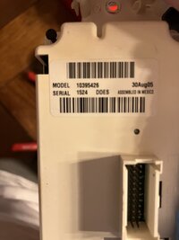
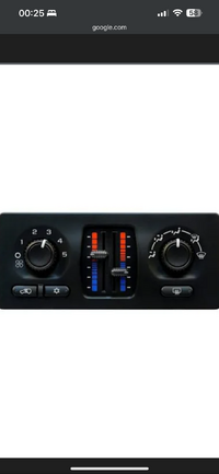
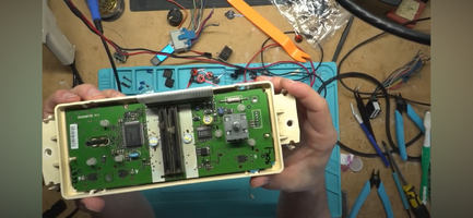
I have the one that’s got a lot more going on in the circuit board. View attachment 115453View attachment 115454View attachment 115454
I have one of these models in my experimental pile.. I'll take a look.
Mooseman
Moderator
There were a bunch of drawings on TV that had the polarities of all modules and switches. Tried to find them and I think they have since been deleted by Photobucket.
Check out our LED Mod thread. The first page has the HVAC module.
 gmtnation.com
Check out our LED Mod thread. The first page has the HVAC module.
LED Mod Thread
Time to make this place feel a lil more homely :biggrin: Alright boys and girls, time to show off your stuff! LED Eyebrows Items used: Pair of 2' side emitting LED strips from Oznium.com Add a fuse (and some wiring) One of the first LED mods I did to my truck. Shown here is version 3.0...
Yeah all i see is this. People say to check resistors for polarity however you can place resistors for these bulbs on either because it’s a series circuit.There were a bunch of drawings on TV that had the polarities of all modules and switches. Tried to find them and I think they have since been deleted by Photobucket.
Check out our LED Mod thread. The first page has the HVAC module.
LED Mod Thread
Time to make this place feel a lil more homely :biggrin: Alright boys and girls, time to show off your stuff! LED Eyebrows Items used: Pair of 2' side emitting LED strips from Oznium.com Add a fuse (and some wiring) One of the first LED mods I did to my truck. Shown here is version 3.0...gmtnation.com
People say to check resistors for polarity however you can place resistors for these bulbs on either because it’s a series circuit.
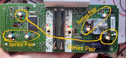
Not sure about exactly how the series works. This is what I have.
Red dots are positive.
Red + green is full + voltage input
Red + white is half + voltage input
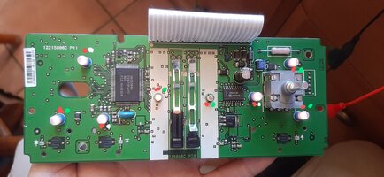
I will update in a short bit to add the 'grounds'
Updated image. Added "grounds" as black dots.
HOWEVER!! None of these "grounds" are either true zero volts, NOR are they equal.
Same goes for the unmarked terminals which measure varying positive voltages approximately half of the input + voltage.
I based these images on a module where I powered the lighting circuits with approximately 6.4 volts then measured voltages at each bulb.
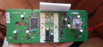

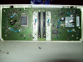
so this is actually the wrong circuit board, i tried this configuration and no luck. there’s actually two different boards with the same front:Updated image. Added "grounds" as black dots.
HOWEVER!! None of these "grounds" are either true zero volts, NOR are they equal.
Same goes for the unmarked terminals which measure varying positive voltages approximately half of the input + voltage.
I based these images on a module where I powered the lighting circuits with approximately 6.4 volts then measured voltages at each bulb.
View attachment 115457
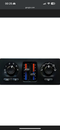
You can see this is the board i’m talking about, (lot more going on in the green):
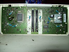
OK, will have a look at another one I have here....so this is actually the wrong circuit board, i tried this configuration and no luck. there’s actually two different boards with the same front: View attachment 115458
You can see this is the board i’m talking about, (lot more going on in the green): View attachment 115459
@benjaminblazer
How about this?
Where I denote "series pair" this means input + voltage comes to the bulb with the red/green dots, exits that bulb and the enters the bulb with the red/white dots, exits that bulb to ground. One complete circuit with 2 bulbs.
There are three such paired sets of bulbs.
At a guess, I would say only one led resistor is needed for each pair of bulbs.
Last edited:
The leds i got im pretty sure have resistors build in, i did my dash and had no issues once i match up polarity. However thanks a lot looks very similar if not the same board i have will try this and let you know! ThanksView attachment 115460
@benjaminblazer
How about this?
Where I denote "series pair" this means input + voltage comes to the bulb with the red/green dots, exits that bulb and the enters the bulb with the red/white dots, exits that bulb to ground. One complete circuit with 2 bulbs.
There are three such paired sets of bulbs.
At a guess, I would say only one led resistor is needed for each pair of bulbs.
The leds i got im pretty sure have resistors build in, i did my dash and had no issues once i match up polarity
I would imagine having 2 resistors in the pair of LEDs would only result in a little less current flow/brightness??
I haven't explored an IPC to see if they also pair up bulbs.
I haven't explored an IPC to see if they also pair up bulbs.
Just checked an IPC. 8 bulbs all individually powered, no series loops.
Huh, that’s odd, must of read something wrong. Does the polarity stay the same then?Just checked an IPC. 8 bulbs all individually powered, no series loops.
Huh, that’s odd, must of read something wrong. Does the polarity stay the same then?
Well yes, the polarity does not change regardless of series looped or not.
And for this HVAC module, knowing that they are installed in series pairs, I would look for LEDs intended for 6 volt power.
With 2 12 volt LEDs in a series each will only receive 6 volts. Not sure that will work.
In your shoes I would hook up a pair of your LEDs in series and give it 12 volts and see if it even works before going through the trouble of installing them.
Gotcha, using the same ones as my 4wd, rear windshield, and front dash that all work so if they are the same 6 volt inputs i should be good. company also told me will work for climate control. But again thanks for all your helpWell yes, the polarity does not change regardless of series looped or not.
And for this HVAC module, knowing that they are installed in series pairs, I would look for LEDs intended for 6 volt power.
With 2 12 volt LEDs in a series each will only receive 6 volts. Not sure that will work.
In your shoes I would hook up a pair of your LEDs in series and give it 12 volts and see if it even works before going through the trouble of installing them.
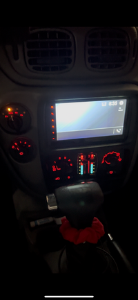
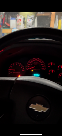
Thanks for all your help, look amazing!Well yes, the polarity does not change regardless of series looped or not.
And for this HVAC module, knowing that they are installed in series pairs, I would look for LEDs intended for 6 volt power.
With 2 12 volt LEDs in a series each will only receive 6 volts. Not sure that will work.
In your shoes I would hook up a pair of your LEDs in series and give it 12 volts and see if it even works before going through the trouble of installing them.
Also does anyone know if the headlight and indoor light control panel has lighting? mine has never lit up since i got the car never thought to try.
Blckshdw
Moderator
Thanks for all your help, look amazing!
Also does anyone know if the headlight and indoor light control panel has lighting? mine has never lit up since i got the car never thought to try.
Nicely done! Those look good. Thinking back, I remember there being some issues with the HVAC polarities, way back when I posted all that stuff. I ended up taking down the polarity map I made, because guys were running into issues with their boards not matching mine.

I know there are a few different versions of the headlight switch module, I've had 2 of them, with different lighting availability. My original one had the dial lit up, the fog light button, and dome light override. Another one added lighting for the dimmer switch, where my original one did not.
I know there are some that don't have a fog light button, but I can't remember the lighting options on that one.

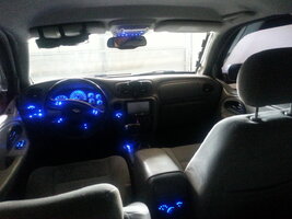
Edit: It's an older pic, but this is how mine looks
Last edited:
Gotcha, imma rip it apart and probably check tomorrow anywayNicely done! Those look good. Thinking back, I remember there being some issues with the HVAC polarities, way back when I posted all that stuff. I ended up taking down the polarity map I made, because guys were running into issues with their boards not matching mine.
I know there are a few different versions of the headlight switch module, I've had 2 of them, with different lighting availability. My original one had the dial lit up, the fog light button, and dome light override. Another one added lighting for the dimmer switch, where my original one did not.
I know there are some that don't have a fog light button, but I can't remember the lighting options on that one.
Here is a 2002 model year with front fogs but no rear fogs.
The 2002 model year headlamp switch cannot be turned counterclockwise beyond the position shown. DRL defeat is achieved by pressing the dome lamp button 4 times in quick succession.
Red dots positive.
3 backighting incandescent lamps. Wired in parallel. (not series loop)
2 LED indicator lights with resistors.
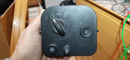
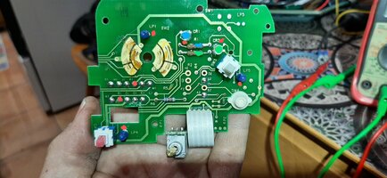


thanks man!Here is a 2002 model year with front fogs but no rear fogs.
The 2002 model year headlamp switch cannot be turned counterclockwise beyond the position shown. DRL defeat is achieved by pressing the dome lamp button 4 times in quick succession.
Red dots positive.
3 backighting incandescent lamps. Wired in parallel. (not series loop)
2 LED indicator lights with resistors.
View attachment 115467
View attachment 115468

