You are using an out of date browser. It may not display this or other websites correctly.
You should upgrade or use an alternative browser.
You should upgrade or use an alternative browser.
Oil Pressure Gage
- Thread starter Mektek
- Start date
Mooseman
Moderator
- Jul 22, 2015
- 2,724
Those V8s are so rare...... Every few months I find one at the local PYP, while there are always around 20 I6 models.
So the video shows that there is a m16x1.5 plug in front of the oil pressure switch. Now I have to find a fitting and a sensor for it. I guess no one has tried installing a permanent gage inside the cab.
Add it to the project list
So the video shows that there is a m16x1.5 plug in front of the oil pressure switch. Now I have to find a fitting and a sensor for it. I guess no one has tried installing a permanent gage inside the cab.
Add it to the project list

The Logistics and Dangers of what you want to do here are More Complex and Hazardous than you might think. Here are all of the serious problems you could encounter:
(1) The GM Atlas 4.2L Engine using the Power of the Gerotor Oil Pump cycling over 11 Gallons of Hot Motor Oil Per Minute around and inside of the Engine Innards at around 3.500 RPM. If you employ a Typical Black Rubber Oil Pressure Hose and it either Burns through and Bursts Open onto the Hot Exhaust Manifold or gets Cut, Shreds or Separates... then the Pressurized Free End of the Open Oil Line WILL get propelled from the escaping Oil at 65 PSI ...and it WILL Whip around inside of there like a Dropped Open Fire Hose Nozzle. This crazy 'Action-Re-Action' WILL wind up Spraying Hot Engine Oil all over the possibly Incandescently Hot Exhaust Manifold. If these unfortunate events happen and should the Hot Engine Oil Ignite... You would have an Uncontrollable, Oil Fed Fire that would almost instantaneously engulf the Engine Nacelle in Flames for as long as the Oil in the Crank Case Lasted ...and for as long as the Engine remained Running.
(2) You COULD try to use something like Flexible Nickel-Steel Brake Lines With Pressure Fittings and Bend an arrangement of Pipe that ends up stopping just short of the Engine Fire Wall. However, you would also need to Create Coil in the Oil Line long enough and "springy" enough to become like "Coiled Snake" arrangement. It would have to be there to act like a Flexible, Tubular Hydraulic Shock Absorber, right in front of where the end of that Oil Line would have to be solidly mounted onto... and Pass through the Firewall into the adjacent SUV Cabin Area. This is quite necessary to accommodate, due to the fact that since the Engine is NOT a Sold State Device... Bolted Solidly to the Body of the SUV... rather it remains free to move about... Gyrating constantly... Forwards, Backwards, Left and Right... on the Two Motor Mounts. And in time, it would make for a chance that the "Oil Piping" Bends would eventually get moved around enough to Work Harden, Crack and Eventually Fail Under Pressure. If that were to happen... You'd find yourself right back at the Original Problem of having to deal with a Fully Involved, Pressurized Oil Fed Fire in your Engine Compartment.
(3) You could try Running a Copper or Nylon Oil Pressure Line ... But then you would have the same problems, as in the case of the Nylon Line....We have already had someone try to do this very same thing (AGAINST THE ADVICE TO ABANDON THAT IDEA ENTIRELY) and after the Nylon Oil Line FAILED WITHOUT WARNING and he lost all Oil Pressure at Highway Speeds. The Happy Result here was that there was NO FIRE. However... he managed by his hard-headed determined actions to "Lunch" his Recently Re-Built Engine ...as immediately afterwards, it seized up at Highway Speeds in the process. None of the Oil Pressure Gauge Kits with Oil Lines include any External Thermal Protection Tubing to protect the Oil Lines from being exposed to all of the Excessive Engine Heat where the Line(s) would have to pass... Hidden ... and underneath the Exhaust Manifold... hugging the Passenger Side of the Engine Block to be Safely out of the way before having to make a Sharp, Right Angle Turn and get routed upwards and adjacent the Engine Firewall.
(4) The Last and Most Serious Issue concerns the Question, "What will happen if the Oil Line that gets attached to the Analog Oil Pressure Gauge mounted somewhere either On or Near the Dash Panel... and it happens to come Loose?" If it were to either Burst or Leak INSIDE OF THE OCCUPIED CABIN of the SUV where OTHER Incendiary objects are capable of lighting that Hot Oil Spray on Fire... Jesus Wept.... How in the Hell would you have enough time to get your Wife and a Baby strapped inside of a Reverse Mounted Car Seat ...Out of the SUV in time to save them if this awful thing were to occur?
Please... Consider what you are doing... and realize that all of these very real tragic consequences can be avoided entirely ...by simply suffering along with the rest of us ... and continuing with using the existing Piezo-Electrical Dashboard Gauges designed into our Trailblazers and Envoys.
Mooseman
Moderator
The Logistics and Dangers of what you want to do here are More Complex and Hazardous than you might think. Here are all of the serious problems you could encounter:
(1) The GM Atlas 4.2L Engine using the Power of the Gerotor Oil Pump cycling over 11 Gallons of Hot Motor Oil Per Minute around and inside of the Engine Innards at around 3.500 RPM. If you employ a Typical Black Rubber Oil Pressure Hose and it either Burns through and Bursts Open onto the Hot Exhaust Manifold or gets Cut, Shreds or Separates... then the Pressurized Free End of the Open Oil Line WILL get propelled from the escaping Oil at 65 PSI ...and it WILL Whip around inside of there like a Dropped Open Fire Hose Nozzle. This crazy 'Action-Re-Action' WILL wind up Spraying Hot Engine Oil all over the possibly Incandescently Hot Exhaust Manifold. If these unfortunate events happen and should the Hot Engine Oil Ignite... You would have an Uncontrollable, Oil Fed Fire that would almost instantaneously engulf the Engine Nacelle in Flames for as long as the Oil in the Crank Case Lasted ...and for as long as the Engine remained Running.
(2) You COULD try to use something like Flexible Nickel-Steel Brake Lines With Pressure Fittings and Bend an arrangement of Pipe that ends up stopping just short of the Engine Fire Wall. However, you would also need to Create Coil in the Oil Line long enough and "springy" enough to become like "Coiled Snake" arrangement. It would have to be there to act like a Flexible, Tubular Hydraulic Shock Absorber, right in front of where the end of that Oil Line would have to be solidly mounted onto... and Pass through the Firewall into the adjacent SUV Cabin Area. This is quite necessary to accommodate, due to the fact that since the Engine is NOT a Sold State Device... Bolted Solidly to the Body of the SUV... rather it remains free to move about... Gyrating constantly... Forwards, Backwards, Left and Right... on the Two Motor Mounts. And in time, it would make for a chance that the "Oil Piping" Bends would eventually get moved around enough to Work Harden, Crack and Eventually Fail Under Pressure. If that were to happen... You'd find yourself right back at the Original Problem of having to deal with a Fully Involved, Pressurized Oil Fed Fire in your Engine Compartment.
(3) You could try Running a Copper or Nylon Oil Pressure Line ... But then you would have the same problems, as in the case of the Nylon Line....We have already had someone try to do this very same thing (AGAINST THE ADVICE TO ABANDON THAT IDEA ENTIRELY) and after the Nylon Oil Line FAILED WITHOUT WARNING and he lost all Oil Pressure at Highway Speeds. The Happy Result here was that there was NO FIRE. However... he managed by his hard-headed determined actions to "Lunch" his Recently Re-Built Engine ...as immediately afterwards, it seized up at Highway Speeds in the process. None of the Oil Pressure Gauge Kits with Oil Lines include any External Thermal Protection Tubing to protect the Oil Lines from being exposed to all of the Excessive Engine Heat where the Line(s) would have to pass... Hidden ... and underneath the Exhaust Manifold... hugging the Passenger Side of the Engine Block to be Safely out of the way before having to make a Sharp, Right Angle Turn and get routed upwards and adjacent the Engine Firewall.
(4) The Last and Most Serious Issue concerns the Question, "What will happen if the Oil Line that gets attached to the Analog Oil Pressure Gauge mounted somewhere either On or Near the Dash Panel... and it happens to come Loose?" If it were to either Burst or Leak INSIDE OF THE OCCUPIED CABIN of the SUV where OTHER Incendiary objects are capable of lighting that Hot Oil Spray on Fire... Jesus Wept.... How in the Hell would you have enough time to get your Wife and a Baby strapped inside of a Reverse Mounted Car Seat ...Out of the SUV in time to save them if this awful thing were to occur?
Please... Consider what you are doing... and realize that all of these very real tragic consequences can be avoided entirely ...by simply suffering along with the rest of us ... and continuing with using the existing Piezo-Electrical Dashboard Gauges designed into our Trailblazers and Envoys.
(1) There are no aftermarket oil pressure gauge kits that have a rubber line except for temporary testing.
(2) There are no aftermarket oil pressure gauge kits that use brake line.
(3) There ARE aftermarket mechanical oil pressure gauge kits that use small copper or nylon lines but can be used successfully without any issues if the line is routed and protected properly. However, these are more difficult to use due to the use of said lines so these have fallen on the wayside. The electrical sensor type gauges are favoured and more commonplace.
(4) Eliminated by using an electrical type gauge.
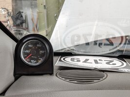
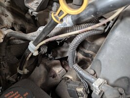
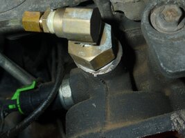
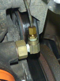
I have a mechanical gauge just tossed up above the dashboard. Put it in to monitor my actual pressure which is sometimes understandably low on my 275 thousand mile motor. I used a nylon (?) Tubing and appropriate fittings at the front of the engine as previously seen in this post. I routed the line up and over the engine keeping it away from mechanical and heat hazards and secured it with an appropriate number of zip ties. The small diameter line gets air bubbles in it and at one time I wanted to see if it behaved differently without the air bubbles. To bleed out the line I disconnected the end of the line at the gauge with the engine running. Even at 65 psi motor oil flowing through a line with an inside diameter somewhere about the size of a hefty sewing needle doesn't move quickly. Drip, drip, drip is about what I got.
Attachments
"How in the Hell would you have enough time to get your Wife and a Baby strapped inside of a Reverse Mounted Car Seat "
Well, first I'd have to take some time to find the wife, and then at least another 9 months for the baby. So this is not a big risk
Well, first I'd have to take some time to find the wife, and then at least another 9 months for the baby. So this is not a big risk

Great!
There is a different adapter
Oil Pressure Sensor Adapter LS Engine Swap
Available on fleabay for $2.89.
There is a nice digital oil pressure sensor/gage combo on fleabay for $11.19 , but this is probably a limited time sale. The sensor would screw directly into the adapter. So you'd just have to run two wires inside and decide where to mount the gage. Nice blue led display.....
This seems to be the ideal solution
I'm glad to find this is not an insurmountable and complex job - actually it may turn out to be a fun job!
So for $14.08 we can have a real digital oil pressure display. No need to sell your I6 powered GMT and buy a v8 just to get a real oil pressure readout!
There is a different adapter
Oil Pressure Sensor Adapter LS Engine Swap
Available on fleabay for $2.89.
There is a nice digital oil pressure sensor/gage combo on fleabay for $11.19 , but this is probably a limited time sale. The sensor would screw directly into the adapter. So you'd just have to run two wires inside and decide where to mount the gage. Nice blue led display.....
This seems to be the ideal solution

I'm glad to find this is not an insurmountable and complex job - actually it may turn out to be a fun job!
So for $14.08 we can have a real digital oil pressure display. No need to sell your I6 powered GMT and buy a v8 just to get a real oil pressure readout!

Last edited:
gmcman
Member
- Dec 12, 2011
- 4,660
I'm actually pursuing the same thing, been looking into 3 options.
Either use the Glow Shift sandwich adapter which allows you to use just an oil pressure gauge or an oil pressure and oil temp gauge.
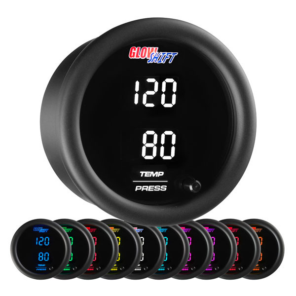
They have a 52MM gauge that has a dual display of oil temp and pressure.

 www.glowshiftdirect.com
 www.glowshiftdirect.com
This will allow you to keep your factory sensor as well as add others.
Another option is the soon to be released Dakota digital quad gauge.
 www.summitracing.com
And finally the Banks igauge 1.8 https://www.bankspower.com/i-2593-6...MIpeXcusSm4wIVFo_ICh1tWQFAEAQYCCABEgK_y_D_BwE
The banks can be expanded with numerous sensors but is also pricey once configured.
Just a pita to configure gauges to the gmt 360.
Either use the Glow Shift sandwich adapter which allows you to use just an oil pressure gauge or an oil pressure and oil temp gauge.
They have a 52MM gauge that has a dual display of oil temp and pressure.

Oil Filter Sandwich Adapter - 13/16-16 Thread
GlowShift Oil Filter Sandwich Adapters with a 13/16-16 Thread Make It Easy to Install Oil Temp and Pressure Sensors Using the Oil Filter Mounting Location.
 www.glowshiftdirect.com

10 Color Digital Dual Temperature & Pressure Gauge
GlowShift’s Dual Digital Temperature/Pressure Gauge combines multiple temperature and pressure readings into one easy-to-use gauge for cars and trucks.
This will allow you to keep your factory sensor as well as add others.
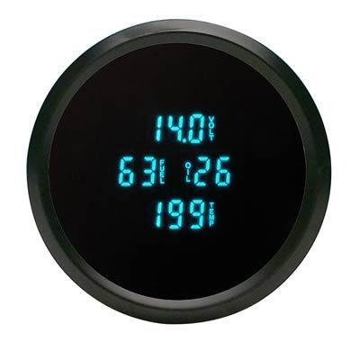
Another option is the soon to be released Dakota digital quad gauge.

Dakota Digital ODYR-40-1 Dakota Digital Odyssey Series II Digital Quad Gauges | Summit Racing
Free Shipping - Dakota Digital Odyssey Series II Digital Quad Gauges with qualifying orders of $109. Shop Gauge Kits and Instrument Clusters at Summit Racing.
And finally the Banks igauge 1.8 https://www.bankspower.com/i-2593-6...MIpeXcusSm4wIVFo_ICh1tWQFAEAQYCCABEgK_y_D_BwE
The banks can be expanded with numerous sensors but is also pricey once configured.
Just a pita to configure gauges to the gmt 360.
I received the gage, sensor and adapter.
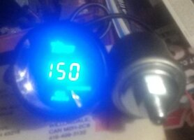
The sensor is quite large. The adapter came a few days later. I think there is a problem- it has a finer thread pitch than the oil pressure switch.
Both are m16 - Is there a different pitch on the threads of the switch and galley plug at the front?
Or did I just get the wrong adapter?

The sensor is quite large. The adapter came a few days later. I think there is a problem- it has a finer thread pitch than the oil pressure switch.
Both are m16 - Is there a different pitch on the threads of the switch and galley plug at the front?
Or did I just get the wrong adapter?
Mooseman
Moderator
The switch threads are different than the other plugs. You have to use the one that points towards the front.
Things rarely go as planned 
The plug is located beneath the middle of the belt tensioner. The 16mm plug has a tiny 8mm hex allen key fitting. I tried to unscrew it but using the allen key with a lever just acted like a spring. So I cut off a piece of the key and inserted into a e12 torx socket and used a ratchet. I applied enough torque to twist the piece of the allen key into a spiral.
So the first effort ended in failure due to stupid engineers specifying a tiny 8mm head. If they used a 16 or 17 mm hex this problem would not exist.
Too risky to use a propane torch on it in such a confined area. All I can do is spray some penetrating oil on it and later try to use a different piece of 8mm allen key that might be stronger. I had a similar problem with the fill plug on the transfer case. Heat and penetrating oil had no effect and even an impact wrench would not remove it. I had to fill the TC through the speed sensor fitting.
Another problem is that the sensor protrudes below the belt tensioner and will prevent it from being lowered enough to remove the belt. I might use an elbow with a flexible copper tube to have the sensor in another place.
If I can get the plug out

Mooseman
Moderator
I think I remember having the same problem on my 5.3 to prime the oil pump. I think I used vice grips on the side of the plug.
So, before everyone starts adding aftermarket sending units and guages, I have a possible solution that uses factory parts, and the factory guage, hopefully.
My other vehicle is a GMT420 Tahoe with the Vortex 5.7 sbc. It has a sending unit that is similar, but longer. The connector has 3 pins instead of 1 because it contains a switch and a transducer. It should fit in place of the factory sending unit.
My idea is to splice the single switch wire to a new 3-pin connector so the computer still receives it's input, then take the other input wires, run then though an Arduino for conversion, then figure out how to interface that with the factory guage in the cluster. I can program the Arduino, but I need the specs and readings for both the sending unit and factory guage.
If this works it will really show how ignorant GM was when putting this vehicle together. It was less of a hassle to actually wire the sending unit than to program trickery into the computer. What would they save, two wires? They already had the sending unit.
Last edited:
Mooseman
Moderator
It is possible that the specs are in GM-SI. I may have sseen iit at some point when I was troubleshooting issues with oil pressure readings in the Saab. Unfortunately I'm away from.home with nno access to my GM-SI machine.
TequilaWarrior
Member
My money is on it being on the bus based on it's erratic behavior, just IMHO.I'll try to figure it out on my own. The hard part is going to interface it with the guage. I think it gets a dedicated 5v signal, but I will have to confirm with a multimeter. I hope it's not part of the data bus.
Looked at the schematic and it is controlled by the bus. What I am thinking is getting a second cluster and isolating the guage from the rest of the cluster electrically. Then I could just hook up the sending unit from my Tahoe to the guage like it is wired in the Tahoe. If it works, great, then I won't have to interface it though an Arduino and it will be even simpler.
It looks like the gauges use stepper motors, which the ones in my Tahoe seem to use regular ones because they return to zero when manually turned. So it looks like it cannot directly wire the new sender to the gauge because it will not work like the Tahoe. I will have to interface it with an Arduino, which is not that hard since I can program them and mini's can be bought for about a dollar on Amazon. I just have to figure out the voltage/pressure steps for the sending unit and look up how stepper motors work to feed that signal to the factory gauge.
It seems like it wouldn't be too hard to hack into the gauge because the solder points and traces are easy to see on the back of the instrument cluster: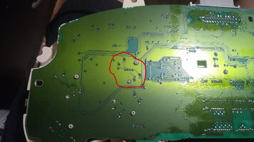
Here is a shot of the wiring diagrams:
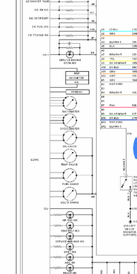
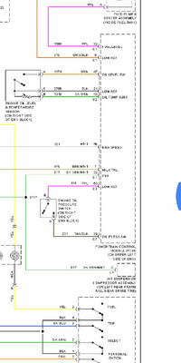
It seems like it wouldn't be too hard to hack into the gauge because the solder points and traces are easy to see on the back of the instrument cluster:

Here is a shot of the wiring diagrams:


Last edited:
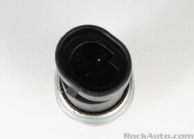
Here is more information on the sending units.
Stock Trailblazer:
ACDELCO D1843A
L31 Sensor:
WVE/AIRTEX/WELLS 1S6635
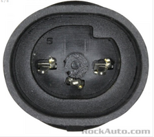
Summit Racing says the tread pattern for the L31 sending unit is 1/4-18 NPT, so it might not fit like I originally thought. I will have to find out in the morning.
Stock Trailblazer:
ACDELCO D1843A

L31 Sensor:
WVE/AIRTEX/WELLS 1S6635

Summit Racing says the tread pattern for the L31 sending unit is 1/4-18 NPT, so it might not fit like I originally thought. I will have to find out in the morning.
The gage is a stepper motor so you would need a controller to interface to the arduino and cut the traces and wire the motor to the controller. Then you would have to write the software to translate the sensor feedback into a stepper position. All of that will be quite a bit of work.
An interesting project if you've got the time and dedication.
A separate gage and sensor is a much easier and quicker install.
An interesting project if you've got the time and dedication.
A separate gage and sensor is a much easier and quicker install.
It would be easier to install a separate one, but that takes the cool factor away. I tend to go above and beyond. Maybe just the Army Aviation in me.
Besides, programming the Arduino will be cake compared to the custom remote start project. Here is a link to that one: https://gmtnation.com/forums/threads/remote-start-on-gmt360.16612/
Besides, programming the Arduino will be cake compared to the custom remote start project. Here is a link to that one: https://gmtnation.com/forums/threads/remote-start-on-gmt360.16612/
Last edited:
Now that I think about it, a few years ago I started development on a arduino based gage. It read the sensor and output to a 2 line lcd with the top line showing pressure and the bottom minimum and maximum pressures. I even had a keypad with a user definable alarm for under and over pressure.
There is a module for stepper motor control and its just a question of writing code to send output to that. The modules cost less than a buck, but they seem to need 5 wires and the gage has 4 wire......
There is a module for stepper motor control and its just a question of writing code to send output to that. The modules cost less than a buck, but they seem to need 5 wires and the gage has 4 wire......
gmcman
Member
- Dec 12, 2011
- 4,660
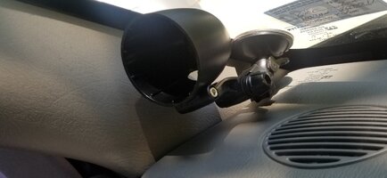
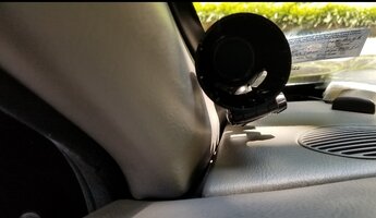
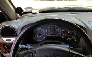
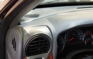
I don't want to hijack the OP's thread but wanted to add that I had to wait for my re-inspection to gain room for the suction mount. New stickers get pasted in the corner of the windshield so I needed about 1/2" to get all glass contact on the suction cup.
Haven't installed the wiring yet, but I went with the Banks Power 52MM suction mount, but had to swap the suction base as the Banks has a fixed axis and my dashcam had a ball mount. The Banks unit works except it needs to be mounted higher, but the ball mount is much easier to tuck down in the corner, also not visible from the side.
Will get more pics after I get the wiring snaked through.


gmcman
Member
- Dec 12, 2011
- 4,660
Was hoping to get the wires run but yard work prevailed. Here's the setup, the sandwich adapter is from Glowshift also and has four ports available...I wish one was plumbed into the center to read pressure in and out of the filter..but this will work.
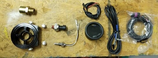
With sensors is their location.
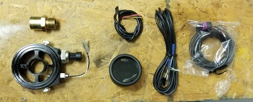
Hopefully time will allow tomorrow to complete this, shouldn't take too long.

With sensors is their location.

Hopefully time will allow tomorrow to complete this, shouldn't take too long.
gmcman
Member
- Dec 12, 2011
- 4,660
For my gauge light I kind of backprobed a connector behind the headlight switch. Soldered probes with heat shrink.View attachment 90220View attachment 90221
Slick idea,.thanks.....

I managed to double check all the pins again and apparently missed one. The dark brown and white wire energizes with the lights, I just need that wire so the gauge dims with the lights on.
Gauge powers up, just need the sandwich adapter put in place but off to bed. Will get the oil filter off in the afternoon and finalize the install. So far so good and will get a short vid also.
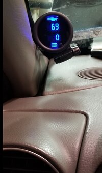
.
gmcman
Member
- Dec 12, 2011
- 4,660
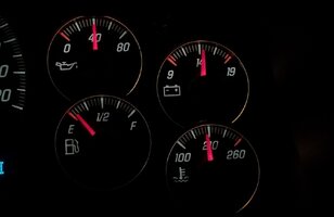
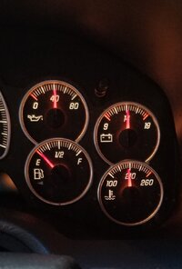
I'll follow this up in a it, but idle pressure is quite different than the stock gauge indicates as we have already discovered.
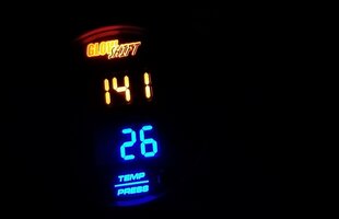
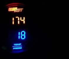
Pressure decreasing as the engine warms, but I can raise the pressure almost 5 lbs at 700 RPM from the 18 PSI shown.
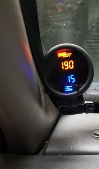
Of course factory gauge is holding at about 40.


Pressure decreasing as the engine warms, but I can raise the pressure almost 5 lbs at 700 RPM from the 18 PSI shown.


Of course factory gauge is holding at about 40.

Last edited:
xavierny25
Member
gmcman
Member
- Dec 12, 2011
- 4,660
@xavierny25 Ha....still had a ways till the light kicked on....
Brief recap...I used the Glow Shift Digital Dual Temp and Pressure Gauge.

 www.glowshiftdirect.com
With the Glow Shift Sandwich Adapter

 www.glowshiftdirect.com
Banks Power 52MM Single Gauge Suction Mount
 www.bankspower.com
I used my swivel dashcam mount that attaches to the pod of the Banks unit but I cannot find a link for it at the moment. This gave me more flexibility in mounting position.
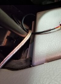
The power wires are easily dropped behind the side pillar, but the sensor wires needed to be pulled up by taping them to a length of speaker wire.
Sensor wires taken through the firewall near the brake booster. Drilled 1/2" hole and used a 3/8" ID grommet.
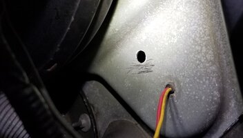
Was easier to insert wires into grommet first then get the grommet seated,.as the connectors are 3/8" across.
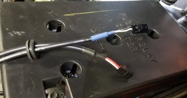
Zip ties on both sides after you get the length set on each side of the firewall. This way you can apply some silicone to the wires and it won't pull the sealer through.
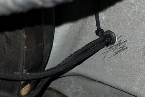
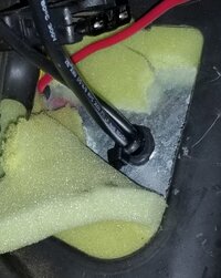
There was just enough wire to reach the gauge allowing a few extra inches tucked away if you need to move the gauge, as well as snake cleanly along the existing looms.
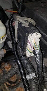

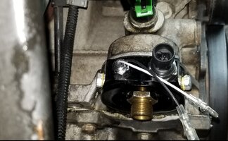
Sandwich adapter:
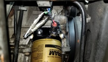
Sensor wires had just the right amount of length.
I'm glad I didn't use a dial gauge as the pressure ranges from 14 PSI to 80 PSI give or take.
The gauge measures both oil temp and oil pressure. You can toggle between 10 different colors, also have different colors for each separate readout.
Driving around tonight the oil temps hovered around 190-192 deg with 75 deg ambient. At 190 deg oil temp, pressure ranges from about 14 PSI at idle, 38 PSI at 1500 RPM, and between 48-53 PSI at 2000 RPM.
With the oil around 120 deg, I have about 50 PSI at idle, again at 190 deg and it's around 14 PSI.
Will be interesting to see how this 0W-40 & 15W-50 blend does with oil temps compared to a dedicated 5W-30.
I would also like to see if it's possible to change the idle speed to 650-700 RPM, and compare pressure results. Probably not needed, been doing well so far. Glad I did.it, wish I had done it sooner.
Comparison of factory gauge to the aftermarket.

Brief recap...I used the Glow Shift Digital Dual Temp and Pressure Gauge.

10 Color Digital Dual Temperature & Pressure Gauge
GlowShift’s Dual Digital Temperature/Pressure Gauge combines multiple temperature and pressure readings into one easy-to-use gauge for cars and trucks.
With the Glow Shift Sandwich Adapter

Oil Filter Sandwich Adapter - 13/16-16 Thread
GlowShift Oil Filter Sandwich Adapters with a 13/16-16 Thread Make It Easy to Install Oil Temp and Pressure Sensors Using the Oil Filter Mounting Location.
 www.glowshiftdirect.com
Banks Power 52MM Single Gauge Suction Mount
Single Gauge Pod Suction Mount [63341] for iDash and 52mm (2-1/16 in) gauges
Sticky suction cup for windshield or dashboard useUniversal suction cup mount designed to work with the iDash and other 52mm (2-1/16 inch) gauges. Adjustable arm for a wide range of mounting angles. U
 www.bankspower.com
I used my swivel dashcam mount that attaches to the pod of the Banks unit but I cannot find a link for it at the moment. This gave me more flexibility in mounting position.
The power wires are easily dropped behind the side pillar, but the sensor wires needed to be pulled up by taping them to a length of speaker wire.

Sensor wires taken through the firewall near the brake booster. Drilled 1/2" hole and used a 3/8" ID grommet.

Was easier to insert wires into grommet first then get the grommet seated,.as the connectors are 3/8" across.

Zip ties on both sides after you get the length set on each side of the firewall. This way you can apply some silicone to the wires and it won't pull the sealer through.


There was just enough wire to reach the gauge allowing a few extra inches tucked away if you need to move the gauge, as well as snake cleanly along the existing looms.


Sandwich adapter:

Sensor wires had just the right amount of length.

I'm glad I didn't use a dial gauge as the pressure ranges from 14 PSI to 80 PSI give or take.
The gauge measures both oil temp and oil pressure. You can toggle between 10 different colors, also have different colors for each separate readout.
Driving around tonight the oil temps hovered around 190-192 deg with 75 deg ambient. At 190 deg oil temp, pressure ranges from about 14 PSI at idle, 38 PSI at 1500 RPM, and between 48-53 PSI at 2000 RPM.
With the oil around 120 deg, I have about 50 PSI at idle, again at 190 deg and it's around 14 PSI.
Will be interesting to see how this 0W-40 & 15W-50 blend does with oil temps compared to a dedicated 5W-30.
I would also like to see if it's possible to change the idle speed to 650-700 RPM, and compare pressure results. Probably not needed, been doing well so far. Glad I did.it, wish I had done it sooner.
Comparison of factory gauge to the aftermarket.


