NEED HELP no speedometer, ABS & Brake lights on, not shifting

John04TB

Original poster
Member
Sep 2, 2023
30
06824
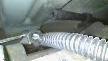
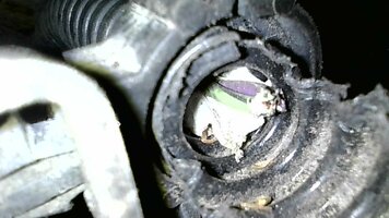
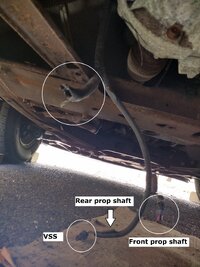
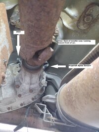
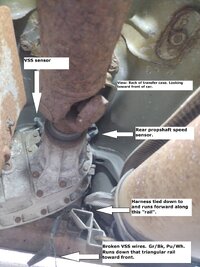
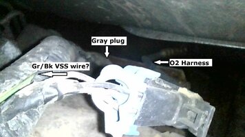
All of a sudden one day I started my '04 TB LS 4WD (130K miles) and the speedometer was dead, the ABS and Parking Brake lights were steadily on and the car wouldn't shift. I read on the other forum how many people replaced the Vehicle Speed Sensor (VSS) and it fixed everything. I did that (after finally locating it) and it changed nothing. I didn't check for an O-ring b/c I saw it on the old VSS when I removed it.

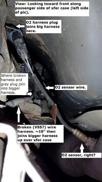
Recently the heat shield(s) above the muffler came completely loose and were rubbing against the driveshaft, particularly on right turns. I realized that was in the vicinity of the VSS but I think (hope) the VSS was too far above the shield and shaft for the shield to hit it or its wires. (And I have already replaced the VSS.)

I also read it could be the EBCM ground wire (and I finally located the EBCM - or ABS Control Module as many call it), but I have no idea where the ground is. Nor how to check continuity, etc.

I also read it could be wheel speed sensors. Last fall I replaced the PS lines and dropped the rack. A couple months ago I replaced both front control arms and struts on both sides. I never disconnected the ABS lines,

At the same time I did the front brakes and replaced the driver side caliper - which I think required me to disconnect the wheel sensor from the hub? I only have a vague memory of that.

And I topped off the brake fluid. There was plenty in the reservoir but I'd read that something that simple could cause these symptoms.

I bought a (cheap) Innova 5210 OBD2/ABS scanner but it didn't find any ABS codes.

Any help would be greatly appreciated. If I do drive it I can only go 15 mph. I hope driving it won't make things worse. Thanks in advance.
 

mrrsm

Lifetime VIP Donor
Supporting Donor
Member
Oct 22, 2015
8,131
Tampa Bay Area
This will sound like an Odd Diagnostic Approach... BUT... Take the time to Watch THIS Video produced by Will Robinson of Robinson's Auto ...Because your Bizarre Dash Lights situation sounds like a Class 2 Network Problem involving a Module on the Network Misbehaving and Bringing Down the Network via UXXXX Codes (U1000).

By following Will's Very Detailed Step By Steps and using a fairly inexpensive VXDIAG-NANO Tech 2 Emulation Scan Tool and conducting Bi-Directional Testing of ALL The Modules on that Network...You will be able to figure out which one is causing all of this trouble. Remember this.... any of the Modules having Comm Problems can make them ALL have problems:


John04TB

Original poster
Member
Sep 2, 2023
30
06824
Wow @mrrsm! That is one educational video! And actually looks doable. Thank you!

I don't think this is my issue though as I'm not getting any network (U) codes. Though I'm not ruling out trying this as I have other electric issues.
 
  • Like
Reactions: mrrsm

TJBaker57

Lifetime VIP Donor
Member
Aug 16, 2015
3,037
Colorado
Personally, I would dismiss thoughts of the EBCM (ABS) system and concentrate on verifying the integrity of the Vehicle Speed Sensor wiring and signal between the VSS which you replaced and the PCM.


  • Love
  • Like
Reactions: mrrsm and budwich

Mooseman

Moderator
Dec 4, 2011
25,891
Ottawa, ON
Merged both threads into one.
 
  • Like
Reactions: TJBaker57

John04TB

Original poster
Member
Sep 2, 2023
30
06824
As I mentioned, the part number is the same for both the Vehicle Speed Sensor and the Rear Propshaft Speed Sensor. The difference is the exact location of the sensor you replaced.
Thanks @Mooseman. I don't know how they got split (or did I post it twice?).

Now that I actually lifted the car I see there are two identical sensors at the cone end of the transfer case. I replaced the "passenger" side one. Is the VSS on the "driver's" side. Looking from behind, toward the front of the engine, one is at 11 o'clock (I call driver side), the other at 1:00. Are they the same part and so interchangeable?
 

John04TB

Original poster
Member
Sep 2, 2023
30
06824
Assuming the driver side (11:00) is the VSS, I removed the new sensor from the other location, put back the original sensor there, and replaced the VSS sensor with the new one. No change in symptoms.
 

Attachments

  • IMG_20240916_154225245 - Copy resized.jpg
    IMG_20240916_154225245 - Copy resized.jpg
    328.3 KB · Views: 10

Mooseman

Moderator
Dec 4, 2011
25,891
Ottawa, ON
I know that the front and rear sensors are the same and some have switched the connectors causing issues with shifting and speedo readings staying at 0. Maybe try switching the connectors.
 

John04TB

Original poster
Member
Sep 2, 2023
30
06824
Uh-oh. This last time under the car I noticed this hanging down. Green and purple wires. I have no idea if it was like that before I had these problems or not. Anyone know where this came from/goes?

IMG_20240916_171346603_HDR - Copy.jpgScreenshot_20240916-171632 - Copy.png
 
  • Like
Reactions: mrrsm

John04TB

Original poster
Member
Sep 2, 2023
30
06824
@TJBaker57 I never touched these wires so that's how they were always twisted. But thanks for the tip.

According to @Mooseman in another post (end of 2019), these are indeed the VSS wires. Now to figure out how to fix them.

"Looked up some schematics and found that the VSS is located at the rear of the TC and has LT GRN/BLK and PPL/WHT wires. "
 

mrrsm

Lifetime VIP Donor
Supporting Donor
Member
Oct 22, 2015
8,131
Tampa Bay Area
VERY Good Catch!

This is Important...

The Number of Twists Per Inch is Critical for the VSS and the Wheel Hub ABS Circuits... Acting as the means to eliminate or reduce Ambient RF (Radio Frequency) Interference being carried by those circuits as the Alternating Current being generated by those Magnetic Induction Coils is VERY Minute. Just bear this in mind during your follow on Repair Procedures. :>)

EDIT:

Uh Oh... Missed @TJBaker57 Post...(Props... for Beating Me to The Punch on this idea...)
 
Last edited:

John04TB

Original poster
Member
Sep 2, 2023
30
06824
Identifying the VSS wire colors confirms that the left/11:00 sensor is the VSS. Where do these broken wires go? (I also realized those wires were dangling in the pics I took of the sensors.)

All the sensors wires go into a plastic sheath that goes above the transmission so I'm not sure how to re-attach these wires.
 

mrrsm

Lifetime VIP Donor
Supporting Donor
Member
Oct 22, 2015
8,131
Tampa Bay Area
Do these Views help to visualize the Harness Routing under your Vehicle...but ... "From 30,000' Above..." and Looking Down from the TOP?

TransferCase_connectors_2.gif

VSSRHARNESSROUTINGl.gif
Sometimes, having a Digital Bore-Scope to Poke Around on Top can be very revealing and give you a chance to take some Snap Shots of Where things ARE --vs-- Where Things SHOULD Be... and perhaps allow for the making of a Short Video as well.

Further, whenever conducting necessary Harness Repairs for installing Heat Shrink Insulating Tubes and when performing Solder Repairs afterwards, Disconnecting as MANY Harness Connectors as POSSIBLE will give you MORE Access and Room to Maneuver and conduct your Harness Wire Repairs. Using a Butane Soldering Kit works BEST under these very difficult conditions.
 
Last edited:

John04TB

Original poster
Member
Sep 2, 2023
30
06824
Thanks @mrrsm. They're both helpful and add to my confusion. LOL.

I wonder if the lower pic is for a 2WD TB? The upper pic looks like my 4WD. From what I've been reading there are actually 3 sensors? Are they ALL the same part?

Based on what I saw, I concluded that 4 was the VSS b/c the connector wire colors are the same as the broken wire colors, Gr/Bl, Pu/Wh. So this diagram confuses me about exactly where the VSS is. A frustration I've had since starting this fix.

Maybe a scope is the way to go. The wires seem ripped off so I need to find where they go. Or find a way to connect them somewhere else.
 

TJBaker57

Lifetime VIP Donor
Member
Aug 16, 2015
3,037
Colorado
Do these Views help to visualize the Harness Routing under your Vehicle...but ... "From 30,000' Above..." and Looking Down from the TOP?

View attachment 114465

View attachment 114466
Sometimes, having a Digital Bore-Scope to Poke Around on Top can be very revealing and give you a chance to take some Snap Shots of Where things ARE --vs-- Where Things SHOULD Be... and perhaps allow for the making of a Short Video as well.

Further, whenever conducting necessary Harness Repairs for installing Heat Shrink Insulating Tubes and when performing Solder Repairs afterwards, Disconnecting as MANY Harness Connectors as POSSIBLE will give you MORE Access and Room to Maneuver and conduct your Harness Wire Repairs. Using a Butane Soldering Kit works BEST under these very difficult conditions.


That top image, the first one, does not appear to be a GMT360/370 transfer case. For one, the shift motor is on the wrong side. Secondly, the VSS and Rear Propshaft Speed sensors are also on the wrong sides. Trailblazer/Envoys VSS is on the left side closest to the shift motor.
 

TJBaker57

Lifetime VIP Donor
Member
Aug 16, 2015
3,037
Colorado
Best SI graphic I could find. Note that number 1 is calling out the encoder motor harness connector, not the motor itself.

Take note of #5. That is where the VSS connects to the engine harness leading to the PCM.

download (1).png
 
  • Like
Reactions: mrrsm and Mooseman

budwich

Member
Jun 16, 2013
2,146
kanata
you also consider what the root cause is for the wiring "dangling" just so your fix results in a permanent fix as opposed to "ongoing an event driven problem".
 
  • Like
Reactions: Mooseman

Mooseman

Moderator
Dec 4, 2011
25,891
Ottawa, ON
Maybe they were chewed by rodents. The wires are made of soy after all.
 
  • Like
Reactions: mrrsm and budwich

John04TB

Original poster
Member
Sep 2, 2023
30
06824
For the life of me I can't see nor figure where these broken wires go. I ended up buying a scope and taking some pictures. Any help is greatly appreciated! I'm driving short trips @ 15 mph with my flashers on! (And now a "Check 4WD System" light came on.)

Note: Gr/Bk should be Gn/Bk. VSS wires are Green/Black, Purple/White.
 

Attachments

  • IMG_20240916_154225245 - Copy resized.jpg
    IMG_20240916_154225245 - Copy resized.jpg
    359.1 KB · Views: 11
  • vlcsnap-2024-09-21-23h52m46s946 - Copy.jpg
    vlcsnap-2024-09-21-23h52m46s946 - Copy.jpg
    463.7 KB · Views: 12
  • IMG_0001 - Copy.JPG
    IMG_0001 - Copy.JPG
    198.5 KB · Views: 10
  • IMG_0007 - Copy.JPG
    IMG_0007 - Copy.JPG
    224.7 KB · Views: 10
  • IMG_0008 - Copy.JPG
    IMG_0008 - Copy.JPG
    198.5 KB · Views: 9

TJBaker57

Lifetime VIP Donor
Member
Aug 16, 2015
3,037
Colorado
From my experience what is shown or otherwise detailed in service literature with regards to wire harnesses is not always exactly what is in the vehicle. So things may look a little different in the vehicle.

In a nutshell, your vehicle speed sensor needs to be connected to the engine harness. The engine harness at the transfer case is the one on the right side of the frame. This is the wiring left hanging in your pictures. It includes the C310 connector.

Those wires need to get over to the actual vehicle speed sensor. The service literature shows those wires going into the chassis harness near the junction to the transfer case shift motor.

From there the literature shows the vehicle speed sensor wires travelling in the chassis harness for a short while then exiting to connect to the vehicle speed sensor.

My guess is your vehicle speed sensor wires are broken inside the chassis harness on top of the transfer case where you will not see the break.

download (2)_20240922093506779.jpg
 

John04TB

Original poster
Member
Sep 2, 2023
30
06824
Thanks @TJBaker57! Finally, a passenger side view. Where do I find those diagrams?

Thank God for another set of eyes. And hands. My buddy reached up and found an empty harness. BINGO! Further up, on top of the transfer case, the harness is ripped open and you can see the green and purple wires (and others?).

Now the challenge is how to fix it in such a tight space. I'm having a hard enough time just trying to open the hold down clamp.

What is that empty black hose(?) in the pic?
 

Attachments

  • IMG_0017.JPG
    IMG_0017.JPG
    78 KB · Views: 9
  • IMG_0018.JPG
    IMG_0018.JPG
    118.5 KB · Views: 9

TJBaker57

Lifetime VIP Donor
Member
Aug 16, 2015
3,037
Colorado

John04TB

Original poster
Member
Sep 2, 2023
30
06824
Thank you all for your help and support. And outrageous thanks to my buddy who found the broken conduit that enabled me to finally fix the broken VSS connector wires.

I couldn't unhook the harness tie-down clip directly above the xfer case - and where the hole in the sheathing was - so I just ripped it off there and took the whole harness down. From there I could heat shrink the wires together and re-install with new sheathing. Whew! It works!

Now, any ideas what to do about the loose heat shields? Re-attach them (and how?)? Can I remove them? There are 2, a long one above the muffler and a short one above the exhaust pipe in front of the muffler.

Both are completely loose. Though given where the hole in the sheathing was, I think @Mooseman is correct that rodents might have caused it and not the heat shields. Are they really made of soy?
 

Attachments

  • IMG_20240923_104712773_HDR - Copy.jpg
    IMG_20240923_104712773_HDR - Copy.jpg
    481.2 KB · Views: 3

Mooseman

Moderator
Dec 4, 2011
25,891
Ottawa, ON
  • Like
Reactions: christo829

Forum Statistics

Threads
23,597
Posts
640,972
Members
18,943
Latest member
Rrachal

Members Online