SOLVED! long crank after engine suddenly stops

Jkb242

Original poster
Member
May 19, 2019
271
CLT
This car runs very well otherwise but recently on two occasions suddenly stops running many lights flash on the dash along with the CEL. Numerous codes set dealing with emissions like PO443,P1516,P1682,P2101,PO443 then cranks but will not start.

Occasionally, it will start after stopping upon cranking showing no codes and run fine but fail again without warning. Could this be an intermittent loss of bias voltage to the security system disabling the engine and then a long crank with no start. These failures occur on the road disabling the vehicle requiring me to tow it to a garage because I can't get it home and in the garage to work on it. I'm about out of free towing using Gieco.

I'm sure I could fix this if I could get in the garage or somewhere remote.

Thanks
 

Mooseman

Moderator
Dec 4, 2011
26,175
Ottawa, ON
Ignoring the evap codes for now, the most concerning would be the throttle actuator codes and ignition circuit. Check ALL the fuses and ensure that the ignition and PCM fuses are getting power with the key on RUN. Try disconnecting the fan clutch connector (you'll get a code for it). If the same, I would next look at the ignition circuit error. Check the ignition switch for proper outputs or just go ahead and replace it.
 

mrrsm

Lifetime VIP Donor
Supporting Donor
Member
Oct 22, 2015
8,303
Tampa Bay Area
This reads like a "Bad or Sketchy" GROUND or Bonding Strap Issue. In the Full Size Trucks...there is a Bonding Strap located on the Rear Passenger Side LS Engine Head that can Break off at the Firewall and cause very similar intermittent Long Start Issues and sudden Stalls.

This may be DIFFERENT as in found at a DIFFERENT LOCATION for the SUVs... But NOT in the Principle, Research your Ground Contact Points and Visually Inspect them ALL for the SLIGHTEST Signs of any Green Corrosion.

Engine Block corrosion issues are GALVANIC in nature, courtesy the Dissimilar Metals involved. This requires a series cleaning of ALL the intermediate Metal Surfaces down to a GLEAM and then applying a Dollop of Dielectric Grease in between where the Ground Wire-Strap Eyelet Tang,,The Engine Block and The Fastener all make Direct Contact with each other. Do some diligent GMTN Site Searches for other similar Grounding Issues ...and you won't be disappointed with what you discover.
 
Last edited:
  • Like
Reactions: Mooseman

Jkb242

Original poster
Member
May 19, 2019
271
CLT
Ignoring the evap codes for now, the most concerning would be the throttle actuator codes and ignition circuit. Check ALL the fuses and ensure that the ignition and PCM fuses are getting power with the key on RUN. Try disconnecting the fan clutch connector (you'll get a code for it). If the same, I would next look at the ignition circuit error. Check the ignition switch for proper outputs or just go ahead and replace it.
Thanks for the input from everyone.

I was ignoring the codes since it seemed logical some codes are always generated whenever there is a sudden loss of power. Because the vehicle is disabled when this occurs, it becomes another tow claim on the insurance making it impossible for me to do anything to address this issue. At this point I am doing damage control seeking input from the professionals here that I truly appreciate and admire. The ignition switch, my original suspect was installed by a local "expensive" garage who was reluctant to even install it and naturally with no guarantee but to crank, nothing more. Afterward it did and ran just fine so I felt confident this was the fix or at least eliminated a major suspect. This was yesterday. Unfortunately it died again same day and disabled again, another tow. This time to a shop I used a few years back who are quite good and honest. He will be looking at it hopefully today. The replacement ignition switch, A Dorman, from Amazon, (I hear everyone laughing and cursing my decision) I had ordered six months ago with the intention of replacing myself.

So why am I posting this? I'm doing damage control to discover what I can to reduce the diagnosis time at the shop. I'm confident he will find the issue "eventually"! Because I cannot get it to my garage to work on it, this is the next best thing I can do next to working on it myself. Who knows, it may come back to me unresolved, another logistical nightmare.

The bad ground makes perfect sense. No supply bus fuses are failing.
It seems to be an obvious intermittent electrical issue hopefully at least eliminating the ignition switch which hasn't felt right for years.
 
  • Like
Reactions: mrrsm

budwich

Member
Jun 16, 2013
2,205
kanata
You are likely better served by being prepared for the next "stoppage / non start" event. Carry a meter and do some testing for "non-start issues" as laid out in the forum. Yes, it might be difficult depending on where it happens and who is around to help if extra hands are needed. Your alternative is "more towing and hope that the destination finds something".

I am somewhat confused by "These failures occur on the road disabling the vehicle requiring me to tow it to a garage because I can't get it home and in the garage to work on it". Get them to tow it to your "house" so you can work on it... maybe?

As last resort, take a picture of the dash when the "crank no start" happens. It might help the forum.
 

Jkb242

Original poster
Member
May 19, 2019
271
CLT
You are likely better served by being prepared for the next "stoppage / non start" event. Carry a meter and do some testing for "non-start issues" as laid out in the forum. Yes, it might be difficult depending on where it happens and who is around to help if extra hands are needed. Your alternative is "more towing and hope that the destination finds something".

I am somewhat confused by "These failures occur on the road disabling the vehicle requiring me to tow it to a garage because I can't get it home and in the garage to work on it". Get them to tow it to your "house" so you can work on it... maybe?

As last resort, take a picture of the dash when the "crank no start" happens. It might help the forum.
That would have been my choice at the first but I have to get the vehicle inside my garage before I can work on it. That isn't possible because the car cannot be moved from the street to the garage since it will not start. I cannot work on my car in the street or a parking space. Community guidelines do not allow that. Thanks
 

Jkb242

Original poster
Member
May 19, 2019
271
CLT
Thanks for the input from everyone.

I was ignoring the codes since it seemed logical some codes are always generated whenever there is a sudden loss of power. Because the vehicle is disabled when this occurs, it becomes another tow claim on the insurance making it impossible for me to do anything to address this issue. At this point I am doing damage control seeking input from the professionals here that I truly appreciate and admire. The ignition switch, my original suspect was installed by a local "expensive" garage who was reluctant to even install it and naturally with no guarantee but to crank, nothing more. Afterward it did and ran just fine so I felt confident this was the fix or at least eliminated a major suspect. This was yesterday. Unfortunately it died again same day and disabled again, another tow. This time to a shop I used a few years back who are quite good and honest. He will be looking at it hopefully today. The replacement ignition switch, A Dorman, from Amazon, (I hear everyone laughing and cursing my decision) I had ordered six months ago with the intention of replacing myself.

So why am I posting this? I'm doing damage control to discover what I can to reduce the diagnosis time at the shop. I'm confident he will find the issue "eventually"! Because I cannot get it to my garage to work on it, this is the next best thing I can do next to working on it myself. Who knows, it may come back to me unresolved, another logistical nightmare.

The bad ground makes perfect sense. No supply bus fuses are failing.
It seems to be an obvious intermittent electrical issue hopefully at least eliminating the ignition switch which hasn't felt right for years.
Follow on Information Requested:

I am continuing to review the possible causes for this failure using the diagrams provided by mooseman. According to the engine wiring diagrams Relay 60 supplies connection to the battery for nearly all circuits for the engine to run. The coil is pulled low by the ECM pin 10 as PWR DIAG. What makes this pin go low to energize relay 60?
Thanks
 
Last edited:

budwich

Member
Jun 16, 2013
2,205
kanata
That would have been my choice at the first but I have to get the vehicle inside my garage before I can work on it. That isn't possible because the car cannot be moved from the street to the garage since it will not start. I cannot work on my car in the street or a parking space. Community guidelines do not allow that. Thanks
OK... but suppose your car is in your garage and you can't get it going or otherwise, does it stay in the garage "forever". No!.... there is ways to get a car into a garage AND out of the garage. Anyway, hopefully, you or your repair center will find the issue and resolve it.
 

mrrsm

Lifetime VIP Donor
Supporting Donor
Member
Oct 22, 2015
8,303
Tampa Bay Area
Post #8

Short Answer? PWM (Pulse Width Modulation)

The PCM uses Internal Mosfets for governing the Six COPs (Coil Over Plugs) via Ground as well as the EFIs based upon the reconciled positions of the #1 Cylinder just BTDC (Before Top Dead Center) and only when in agreement with the Crankshaft Position Sensor (CKP) via its A/C Sine Wave and the Absolute Exhaust Camshaft Position Signal, sensed via the Camshaft Position Sensor Square Wave of the (CMP) generated by the rotating Cam Phaser Six Position Reluctor "Notches".

If any one of those COP Coils has an internal Dead Short, then the PCM will act to protect itself ...and Neither allow the vehicle to Start, Nor allow it to stay Running.
 

Jkb242

Original poster
Member
May 19, 2019
271
CLT
Thanks for your detailed response. I was not complete aware of the crank position sensor and how the mechanical timing was related to the running dynamics for timing advances. This helps.

When I mentioned the coil I was referring to the relay coil of relay 60, not any of the 8 ignition coils. This is pin 10 on the ECM labeled PWR DIAG. Are you saying that this pin goes from low (coil energized) to high, to unlatch relay 60, disconnecting the main 12 feed to practically all run circuits in the event the ECM detects a shorted ignition coil? Is that the only current it's monitoring to disengage this relay?

Just to clarify what was seen regarding instrument lights when the engine dies, practically all lights are illuminated but unsure if they flash or extinguish since I was not driving any of the times this event took place. The first occurrence of this issue was when the car was parked idling with the AC running for 1/2 hour or more on a pretty warm day last week.

Much thanks
 

Jkb242

Original poster
Member
May 19, 2019
271
CLT
P1682 was one of the codes generated when the engines dies. If the primary cause for the code is a difference between Ign 0 and Ign 1 voltages does anyone know the value or threshold difference the ECM is set to detect?

Since the “Driver 5 Line 2” description is shown on my code reader I presume the google search below correctly identifies the cause:

“ P1682 on GM Vehicles​

On GM vehicles, the code P1682 is defined as “Driver 5 Line 2.” The code is set when the vehicle’s computer detects that the voltage difference between circuit 1 and circuit 2 is higher than the maximum threshold set by GM.”

I would like to understand if the delta is >0.5v or something closer to > 5-12v. It would help in troubleshooting to evaluating any measured difference.

Thanks.
 

mrrsm

Lifetime VIP Donor
Supporting Donor
Member
Oct 22, 2015
8,303
Tampa Bay Area
Another visual look at the situation... and even though though this Video is for the GM 4.2L Atlas In-Line Six Cylinder Engines... Conceptually... THIS Diagnostic and Repair Approach would also apply for the LS V8 5.3L Engines (P01 PCM) as well:

 
Last edited:
  • Like
Reactions: Mooseman

mrrsm

Lifetime VIP Donor
Supporting Donor
Member
Oct 22, 2015
8,303
Tampa Bay Area
It looks like he DID... By Checking the Yellow Wire Continuity leading FROM the Un-Hooked PCM Connector -- towards-- the direction of the FUSE BLOCKS ...and Likewise... leading FROM the FUSE BLOCK --towards-- the direction of the PCM Connector.

Wherever the ACTUAL Break In The Wire "Happened" ...would simply be Academic and unnecessary to locate... as long as he was able to get CONTINUITY reliably at BOTH of the remaining Short Lengths of the Two Foreshortened Yellow Wires. Then it becomes a Very Easy Repair.

Once he established these Two, Separate and Reliable Electrical Paths... then by adding in -- just enough length -- of a Replacement Wire Segment in between after FIRST Slipping on the Two Heat Shrink Insulation Tubes over the ends of that Middle Segment and then securing both ends via Soldering and Heating both Insulators... It Makes For A PERFECT Repair!
 
Last edited:
  • Like
Reactions: Mooseman

Jkb242

Original poster
Member
May 19, 2019
271
CLT
Another visual look at the situation... and even though though this Video is for the GM 4.2L Atlas In-Line Six Cylinder Engines... Conceptually... THIS Diagnostic and Repair Approach would also apply for the LS V8 5.3L Engines (P01 PCM) as well:

Very nice thanks.

Relay 60 (on the 5.3L) was always suspect as well as Ign0 and Ign1 once I began studying the wiring diagram, AFTER dropping the vehicle at the garage.

Without relay 60 pulling in, both Ign0 and Ign1 are 0v, discounting any capacitive charge remaining on either bus which led to my previous questions regarding the trigger threshold issue for relay 60

There is a lot going on in my person life with my wife being sick, sorta over-rode my normal logic of having the vehicle towed to my driveway with a 9⁰ slope, to fix it myself, instead of towing it to the shop. We have “HOA RAT patrol issues but in the garage you can make moonshine, if you choose.

With my issue being intermittent, diagnosis might be the same but confirmation requires a lot more “hood up” time in the driveway (HOA). Learning that a 1682 code was possible with both Ign0 and Ign1 at 0 is valuable. Relay 60 contacts as well as the presence of both Ign voltages would have been my first step after looking at the wiring diagrams.
Last I checked with the shop, no failure. Obviously, this could go on for some time but at some point I will have it towed to my driveway and take my chances with the scum bag “HOA COPS”. I will fix this!

Much thanks indeed!!
 
  • Like
Reactions: Mooseman

Jkb242

Original poster
Member
May 19, 2019
271
CLT
Very nice thanks.

Relay 60 (on the 5.3L) was always suspect as well as Ign0 and Ign1 once I began studying the wiring diagram, AFTER dropping the vehicle at the garage.

Without relay 60 pulling in, both Ign0 and Ign1 are 0v, discounting any capacitive charge remaining on either bus which led to my previous questions regarding the trigger threshold issue for relay 60

There is a lot going on in my person life with my wife being sick, sorta over-rode my normal logic of having the vehicle towed to my driveway with a 9⁰ slope, to fix it myself, instead of towing it to the shop. We have “HOA RAT patrol issues but in the garage you can make moonshine, if you choose.

With my issue being intermittent, diagnosis might be the same but confirmation requires a lot more “hood up” time in the driveway (HOA). Learning that a 1682 code was possible with both Ign0 and Ign1 at 0 is valuable. Relay 60 contacts as well as the presence of both Ign voltages would have been my first step after looking at the wiring diagrams.
Last I checked with the shop, no failure. Obviously, this could go on for some time but at some point I will have it towed to my driveway and take my chances with the scum bag “HOA COPS”. I will fix this!

Much thanks indeed!!
UPDATE FROM SHOP

After the vehicle idles for close to an hour it fails. That’s exactly what it did when this issue first occurred. This issue could be temp related (engine remained within normal temp range). Physical expansion of a poor electrical connection could reach a point where the electrical resistance also increases which causes additional heat due to I²R losses ending in failure of the circuit. Relay 60 for example would be a classical Issue. However, that would affect both Ign0 and Ign1 equally. Unfortunately, the shop wasn’t able to measure either Ign buss with the Ign switch on at the time of failure to rule in or rule out relay 60 or equal bus voltages. is suspect.
 

mrrsm

Lifetime VIP Donor
Supporting Donor
Member
Oct 22, 2015
8,303
Tampa Bay Area
Now we are very likely talking about THIS being the issue:

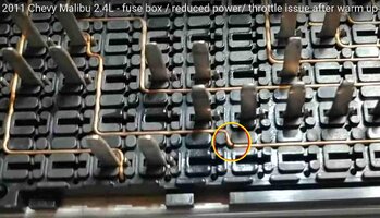
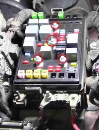
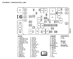
Fractured Copper 20 GA Wire Breaks at the Right Angle Apex Points ...somewhere inside and underneath the Sandwiched Fuse Box Segments. This Diagnostic and Repair requires:

"A Graduated Eye-Ball, A Magnifying Lens and...A Decent High Temp -Tiny Tipped Soldering Iron ... using Silver Solder":

FUSECOPPERBREAK.jpgFUSEOPPERBREAK2.jpgTIGHTENTHESEDOWN.jpgunnamed.gifPWRDISTCENTR.jpeg2003-trailblazer-fuse-box-diagram-11.gif


One Last Item that can speed things along is to use a Decent DMM set to CONTINUITY TEST and use the two Pin Probes on either side of the Right Angle Bends...if the Sound Alert STOPS...Suspect a Hidden Crack in that Copper Segment.
 
Last edited:

Jkb242

Original poster
Member
May 19, 2019
271
CLT
Is this a classic failure for both the 5.3L and 4.2L? The pictures you posted are very interesting especially regarding with the formed wire bending radius. Since I did not actually get to put “hands on” this one, to I did not know the formed wiring of fuse holding tray was constructed in this is way. I’m a retired EE so circuit analysis and troubleshooting is not a challenge for me but having the wiring diagrams was invaluable. Glad I was able to get them here. Not being able to get hands and eyes on this is frustrating indeed so I’m keeping in contact with the shop in order to be helpful yet not to overly so to be a bother. Thanks for the very helpful photos and info!!
 
  • Like
Reactions: mrrsm

budwich

Member
Jun 16, 2013
2,205
kanata
UPDATE FROM SHOP

After the vehicle idles for close to an hour it fails. That’s exactly what it did when this issue first occurred. This issue could be temp related (engine remained within normal temp range). Physical expansion of a poor electrical connection could reach a point where the electrical resistance also increases which causes additional heat due to I²R losses ending in failure of the circuit. Relay 60 for example would be a classical Issue. However, that would affect both Ign0 and Ign1 equally. Unfortunately, the shop wasn’t able to measure either Ign buss with the Ign switch on at the time of failure to rule in or rule out relay 60 or equal bus voltages. is suspect.
?? does the "crank but no start" condition result?
 

Mektek

Member
May 2, 2017
661
FL
I've had similar issues before. Driving down the road for half an hour and the engine suddenly stops. After coasting to a stop I can restart and it seems ok. But two weeks later it happened again. It was different in that after restarting the engine would run for a few minutes and quit.
I replaced the fuel pump and the problem never recurred.
This has happened to me before in another car. I went through the diagnostics steps and drove with a fuel pressure gauge taped to the windshield. It was a bit different in that it would not restart after shutdown. But after sitting for a few hours it would restart. Also bad fuel pump.
So when the TB started displaying similar symptoms I felt confident it was the same issue.
I used a low cost pump that has been running for years without issues.
When it quits check the fuel pressure. Cycle the ignition and if you don't get 50 psi or so then you have a problem.
 

Jkb242

Original poster
Member
May 19, 2019
271
CLT
Refined Request Related To Original Post

I can’t find an illustration in the manuals I have from here showing the ECM connector numbers for the 5.3L Denali Sport. I have only found an illustration showing the 4.2L.

If this illustration is included in the GM manuals from here please tell me the section and I’ll search but so far all I found was the illustration for the 4.2L ECM.

Thanks
 

mrrsm

Lifetime VIP Donor
Supporting Donor
Member
Oct 22, 2015
8,303
Tampa Bay Area
You don't mention the YEAR of Vehicle Manufacture here... So, see if THIS Thread in another Forum will be relevant.

Trust NOTHING until you have perused EVERYTHING in this Link and then compare the Pin-Out Listings vs, the Binary Wire Color Codes for the SAME Positions between the mentioned Pin-Outs below vs. YOUR Color Wires at the SAME for YOUR PCM Locations and your OWN PCM Connectors... Also... Mind the Color Differences in the Outer Connector Covers, too!


PS.... For the Better Understanding of the Diagnostic TACTICS...THIS is a Pretty Good Thread,,,even if I do say so...Myself:


Mooseman

Moderator
Dec 4, 2011
26,175
Ottawa, ON
I have from here showing the ECM connector numbers for the 5.3L Denali Sport.
It should be the same thing. Engine wise, they're the same.
 

Jkb242

Original poster
Member
May 19, 2019
271
CLT
I've had similar issues before. Driving down the road for half an hour and the engine suddenly stops. After coasting to a stop I can restart and it seems ok. But two weeks later it happened again. It was different in that after restarting the engine would run for a few minutes and quit.
I replaced the fuel pump and the problem never recurred.
This has happened to me before in another car. I went through the diagnostics steps and drove with a fuel pressure gauge taped to the windshield. It was a bit different in that it would not restart after shutdown. But after sitting for a few hours it would restart. Also bad fuel pump.
So when the TB started displaying similar symptoms I felt confident it was the same issue.
I used a low cost pump that has been running for years without issues.
When it quits check the fuel pressure. Cycle the ignition and if you don't get 50 psi or so then you have a problem.
Thanks for the feedback and good tip.
I’ll check that if the shop who has it now hasn’t already made that test or gives up.
 

Jkb242

Original poster
Member
May 19, 2019
271
CLT
It should be the same thing. Engine wise, they're the same.
moose man are you saying that you have the ECM illustration showing the connector ID's for the 5.3L? As stated, I was only able to find the illustration for the 4.2L engine. Please advise as I would like to see this ASAP. The car is being delivered to me from the garage who was attempting to locate the issue so that I can begin a logical troubleshooting process. Thanks indeed.
 

Jkb242

Original poster
Member
May 19, 2019
271
CLT
You don't mention the YEAR of Vehicle Manufacture here... So, see if THIS Thread in another Forum will be relevant.

Trust NOTHING until you have perused EVERYTHING in this Link and then compare the Pin-Out Listings vs, the Binary Wire Color Codes for the SAME Positions between the mentioned Pin-Outs below vs. YOUR Color Wires at the SAME for YOUR PCM Locations and your OWN PCM Connectors... Also... Mind the Color Differences in the Outer Connector Covers, too!


PS.... For the Better Understanding of the Diagnostic TACTICS...THIS is a Pretty Good Thread,,,even if I do say so...Myself:

Much thanks for this information. The my vehicle is a 2006 Sport Denali with the 5.3L engine. This is listed in my profile and thought it was captured in my posts bur apparently not. I like the breakout box solution mentioned, I was unaware it was available. There were three of these listed on Amazon using the link. They all appear to be identical but none have 16 LED's but probe access to the 16 ECM ports. Is there any particular break out box that is recommended. I'm ordering this along with the pin and back probes so please advise if possible. I do not have a bidirectional scan tool but a Foxwell NT630 Pro code reader as well as a Fluke 17 DVM along with a Rigol Bench Storage Scope for examining the constant and PWM signals.

The troubleshooting process you posted makes perfect sense. I do not have a "No Communication" code as in the case of this video but apparently may have the classic fuse box internal wire failure. The symptoms I have with my vehicle are identical to those captured in the videos posted here for this failure.

I am finally getting the vehicle back after the garage was never able to duplicate the primary complaint. Finally, I will be able to troubleshoot this for the first time since the trouble began. Thanks for what you have provided thus far, now If I can get it to fail for me in my garage. I'll report back soon. Thanks!!
 
  • Like
Reactions: mrrsm

Mooseman

Moderator
Dec 4, 2011
26,175
Ottawa, ON
moose man are you saying that you have the ECM illustration showing the connector ID's for the 5.3L? As stated, I was only able to find the illustration for the 4.2L engine. Please advise as I would like to see this ASAP. The car is being delivered to me from the garage who was attempting to locate the issue so that I can begin a logical troubleshooting process. Thanks indeed.
I thought from your post that you said you had it for the Denali. Anyway, I did find one in my manuals downloads but it's not the best. It's on page 160-161:

2006 Electrical connectors and components locations
 

TJBaker57

Lifetime VIP Donor
Member
Aug 16, 2015
3,341
Colorado
you have the ECM illustration showing the connector ID's for the 5.3L?


I must confess I have read this thread several times but I'm not sure what you are seeking here with this question.

Are you looking for the ECM connector numbers? There are 3 connectors to the ECM, Connector 1 is blue in color, connector 2 is black and connector 3 is gray. Is this what you are asking about?

Or are you looking for the pinouts of each of these 3 connectors?

I see the pinouts represented in the "wiring.pdf" for the 2006 model year in Moosemans downloads. Around page 48 of that document the circuitry for the 5.3 engine code "M" (8th character in VIN) begins and is covered in 5 pages between the 4.2 VIN S and the 6.0 VIN H engines PCMs.

Am I completely missing something here?
 
  • Like
Reactions: mrrsm and Mooseman

TJBaker57

Lifetime VIP Donor
Member
Aug 16, 2015
3,341
Colorado
Without relay 60 pulling in, both Ign0 and Ign1 are 0v,


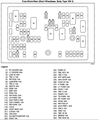
Not so. IGN 0 is supplied to the PCM from the ignition switch through the IGN 0 fuse #47 in the rear fuseblock.


P1682 was one of the codes generated when the engines dies. If the primary cause for the code is a difference between Ign 0 and Ign 1 voltages


Not a difference between IGN 0 and IGN 1. A difference seen in two different circuits that both supply the IGN 1 power signal.

Copy/Paste from online manual at Charm.li.

CIRCUIT/SYSTEM DESCRIPTION
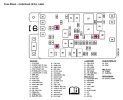
There are 2 ignition 1 voltage circuits supplied to the engine control module (ECM). The first ignition 1 voltage circuit is provided by the powertrain relay, through the TAC fuse, located in the underhood fuse block. This ignition 1 voltage circuit supplies power to all the internal ECM circuits associated with the throttle actuator control (TAC) operation, and to both TAC motor control circuits to the throttle body. The ignition switch provides the second ignition 1 voltage circuit to the ECM, through the ECM 1 fuse located in the underhood fuse block. This ignition 1 voltage provides power to all internal ECM circuits, except those associated with TAC operation. The ECM continuously monitors both ignition 1 voltage circuits. If the ECM detects a voltage level difference between the two circuits, DTC P1682 will set.
 
  • Like
Reactions: mrrsm and Mooseman

mrrsm

Lifetime VIP Donor
Supporting Donor
Member
Oct 22, 2015
8,303
Tampa Bay Area
Re: Post #29 Questions about "BOB"... (Break Out Box)...

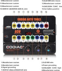
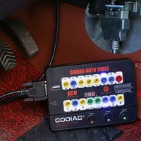
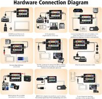
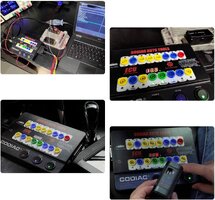
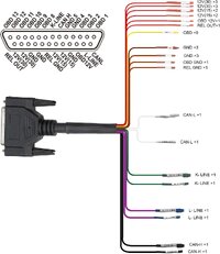
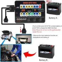
My favorite so far has been this REALLY Full Featured GODIAG GT-100+ "BOB" that, while double the average price on Amazon, when compared with other Generic Chinese Off Brands... THIS Thing is remarkably Full Featured and is also very useful for Bench Top Diagnostics of Modules when addressing PCM to individual Module (Programming in Calibrations) and other Activities. I try hard to avoid "Touting" any equipment which I do not actually own or have not actually used... So from Personal, Hands-On Experiences with using this Kit... I can suggest that THIS "BOB... is a Real KEEPER:


81LjwtwbVOL._AC_SL1500_.jpg81FeD9rHApL._AC_SL1500_.jpg81fcVbBzkOL._AC_SL1500_.jpg81eD21eON8S._AC_SL1500_.jpg71ylMBYyHIL._AC_SL1500_.jpg71nzOc8MIeL._AC_SL1500_.jpg
 

Attachments

  • 61y0fY8QxML._AC_SL1000_.jpg
    61y0fY8QxML._AC_SL1000_.jpg
    100.4 KB · Views: 2
  • 71mHVPunsVL._AC_SL1000_.jpg
    71mHVPunsVL._AC_SL1000_.jpg
    116.7 KB · Views: 1
Last edited:

Jkb242

Original poster
Member
May 19, 2019
271
CLT
I thought from your post that you said you had it for the Denali. Anyway, I did find one in my manuals downloads but it's not the best. It's on page 160-161:

2006 Electrical connectors and components locations
Thanks, I see it. I wasn’t looking in that section of the manual. I was looking in the Engine Electrical section where I saw the ECM/TCM connections for the 4.2L Envoy and thought there might be an illustration of same for the 5.3L which is what I have. For some reasons these connections were not shown or identified.
 

Jkb242

Original poster
Member
May 19, 2019
271
CLT
Re: Post #29 Questions about "BOB"... (Break Out Box)...

My favorite so far has been this REALLY Full Featured GODIAG GT-100+ "BOB" that, while double the average price on Amazon, when compared with other Generic Chinese Off Brands... THIS Thing is remarkably Full Featured and is also very useful for Bench Top Diagnostics of Modules when addressing PCM to individual Module (Programming in Calibrations) and other Activities. I try hard to avoid "Touting" any equipment which I do not actually own or have not actually used... So from Personal, Hands-On Experiences with using this Kit... I can suggest that THIS "BOB... is a Real KEEPER:


View attachment 114564View attachment 114565View attachment 114566View attachment 114567View attachment 114568View attachment 114569
RE POST 33 Regarding BOB

I don’t have programming software or desire to get that deep. The BOB referenced in the Amazon links and the video, was something new to me and I wanted to understand how it might be useful for me in troubleshooting my current issue. Since I do not have a “no com” issue but rather an intermittent one that is either connection/component based (wiring or the fusebox circuit failure). I looked over the BOB a bit more closely today. Unless I’m overlooking something, I don’t see how it would help me. Please correct me if I have done so. My aim is to confirm/ eliminate certain basic connections that must be present to prevent engine shutdown once this failure occurs. Since the engine cranks at failure but doesn’t start, this seems to be an IGN on power distribution issue. With IGN on:

*Powertrain Relay operation and voltage to the designated ECM pin.
*Presence of IGN 0 and 1 bus all branches
*Presence of IGN on voltages to the two primary branch fused circuits for all coils and injectors at the fuse box.
*Presence of fuel pressure at test port. The fuel pump has its own relay and fused circuit.

The biggest challenge is getting it to fail.

When the engine runs, it’s completely normal no misfires or other irregularities.
 

mrrsm

Lifetime VIP Donor
Supporting Donor
Member
Oct 22, 2015
8,303
Tampa Bay Area
I was a bit hesitant to Answer these Off -Topic Questions...But I wanted to be comprehensive with my reply. The "BOB" will not be directly necessary in sorting out your present situation... I was simply responding to THIS inquiry you posted:

"I like the breakout box solution mentioned, I was unaware it was available. There were three of these listed on Amazon using the link. They all appear to be identical but none have 16 LED's but probe access to the 16 ECM ports. Is there any particular break out box that is recommended. I'm ordering this along with the pin and back probes so please advise if possible."
 

Jkb242

Original poster
Member
May 19, 2019
271
CLT
Thanks I appreciate the info
This car runs very well otherwise but recently on two occasions suddenly stops running many lights flash on the dash along with the CEL. Numerous codes set dealing with emissions like PO443,P1516,P1682,P2101,PO443 then cranks but will not start.

Occasionally, it will start after stopping upon cranking showing no codes and run fine but fail again without warning. Could this be an intermittent loss of bias voltage to the security system disabling the engine and then a long crank with no start. These failures occur on the road disabling the vehicle requiring me to tow it to a garage because I can't get it home and in the garage to work on it. I'm about out of free towing using Gieco.

I'm sure I could fix this if I could get in the garage or somewhere remote.

Thanks
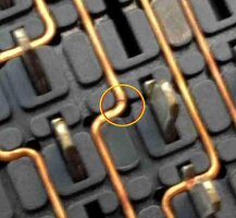
Update Regarding This Issue

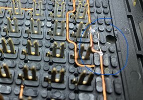
FInally got my vehicle home from the garage who was unable, to repair it. Diagnosis: Shorted ECM and Bad Fuse box. No used parts available and frankly spend that much on a used part with no guarantee?? I drove it home luckily without it dying again. Removed and disassembled fuse box found hairline crack in powertrain circuit and confirmed with introduction of heat circuit would indeed open. Repaired soldering a 22ga short jumper around copper buss. Tested with heat applied, no failure. Re-assembled fuse box re-installed and all seems fine. The real test will be driving and cycling in normal use. Since the open circuit was confirmed then corrected I feel pretty confident this has addressed the original issue.

I did encounter a discharged battery before the repair that occurred over night after getting it home from the garage which was the first time this happened. I’ll see how this goes now as it sits overnight but don’t think that is related to the original issue. Attaching one photo of the repair and happy to post others as requested.

Thanks
 

Attachments

  • IMG_0509.jpeg
    IMG_0509.jpeg
    611 KB · Views: 18

mrrsm

Lifetime VIP Donor
Supporting Donor
Member
Oct 22, 2015
8,303
Tampa Bay Area
SOLVED!.jpg (Sweet!)
 

Mooseman

Moderator
Dec 4, 2011
26,175
Ottawa, ON
You can definitely see where the crack was making it heat up and melting the plastic. Good job on finding the problem.

FInally got my vehicle home from the garage who was unable, to repair it. Diagnosis: Shorted ECM and Bad Fuse box.
So that was their diagnosis without actually verifying, especially the fuse box where it could have been repaired like you did. I hate shoddy shops. And they wonder why we mistrust them :mad:

If the ECM does prove to be bad, which I doubt very much now, they are a dime a dozen in u-pull yards. Just get the same year and gearing, do the 30 minute security relearn and you're off and running.
 
  • Like
Reactions: mrrsm

Jkb242

Original poster
Member
May 19, 2019
271
CLT
A drive test today involving most stop and go covering over 30 miles plus a long idle of about 40 min. with AC on. This has not been possible since the fuse box circuit failure. This repair has fully addressed the original issue.

I would be happy to offer assistance to anyone having this issue regarding the repair and the technique I used to find and permanently repair. Without going into a log of detail at this point I chose to solder this under a microscope to make certain the bypass and copper circuit were fully flooded with 60/40 solder. Silver solder was not an option due to much higher melting heat and the necessity to use a small soldering tip.

Thanks
 

Forum Statistics

Threads
23,749
Posts
642,937
Members
19,329
Latest member
Ruslan

Members Online

No members online now.