How to Use a Parasitic Draw Test Switch & Cable


PRECAUTIONS:
ALWAYS WEAR EYE PROTECTION
REMOVE ALL RINGS, WATCHES AND JEWELRY
DO NOT CONNECT THE TEST SWITCH TO THE POSITIVE (+) BATTERY TERMINAL
DO NOT OPEN THE TEST SWITCH WITH THE ENGINE RUNNING… ELECTRICAL SYSTEM DAMAGE MAY OCCUR
CHECK THAT ALL CONNECTIONS ARE CLEAN AND TIGHT
BATTERY CONNECTIONS:
(1) Turn the Ignition OFF.
(2) Disable the Under Hood Light.
(3) Remove the (-) Negative Battery Cable.
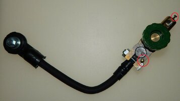
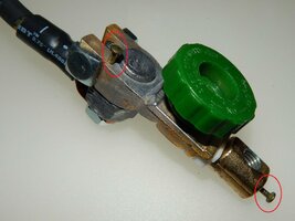
(4) Install the Test Switch Side Mount Cable Bolt to the (-) Battery Terminal.
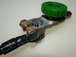
(5) Alternatively, Attach the Top Mount Cable Connector to the (-) Battery Post.
(6) Install the OEM (-) Negative Battery Cable to the Test Switch.
(7) Turn the Green Test Switch Knob to the “ON” Position.
(8) Start the Vehicle and Take a Short Test Drive to Test All Normal Systems.
(9) Turn the Ignition Key to the “OFF” Position.
(10) Wait 20 Minutes.
(11) Set the Ammeter to the 10 Amp Scale and Connect the Leads to the Test Switch Terminals.
(12) Turn the Green Test Switch Knob to the “OFF” Position.
(13) Measure the Amperage.
(14) If the Ammeter reads Below 2 Amps… Turn the Test Switch “ON”.
(15) Switch the Ammeter to the Milli-Amps (mA) Scale.
(16) Turn the Green Test Switch Knob to the “OFF” Position.
(17) Measure the Amperage in Milli-Amps (mA). THAT Reading is the Parasitic Draw.
NOTE:
ALWAYS Turn the Green Test Switch Knob to the “ON” Position before Opening the Vehicle Door to Remove a Fuse to Avoid Damage to the Ammeter.
(18) If the Parasitic Draw is TOO HIGH (Above acceptable Limits) Remove One Fuse at a Time until the Parasitic Draw returns to Normal. Refer to the Vehicle Electrical Circuit Diagram(s) to Trace down which components are the cause of the problem.
EDIT: PDF Modified on Wednesday, March 18th, 2020 @ 11:31 PM
I've converted this Instructional to a PDF Document attached below:
Attachments
Last edited:

 This has application to my newer non GMT that I am becoming familiar with since purchasing at end of Feb.