Hello everyone,
So let me start by saying I stumbled across your forum while searching the internet for any information regarding GM class 2 data network over J1850 bus. You see the rabbit hole I voluntarily threw myself down brought me here. I've victoriously resurfaced and I'm here to share everything I learned so that the next guy/gal who is starting down that hole doesn't have as far to go as I did.
I have a 65 Chevy II SS that I've had the privilege of owning and driving since 1993. Bought from the original owners for $900.00. Since then, she’s had 2 paint jobs and lots of modifications. Right now, she's way back on the back burner because of life and the many kids that I have now. I'm always yearning to get her back on the road, but life seems to be winning that tug-a-war for now. I've always wanted to add power steering to my Nova and since I'm now running a Fat Man Strut conversion kit on her with rack and pinion steering, I really wanted that extra help when maneuvering in tight spaces. I just recently learned of this anomaly called Electric Power Steering which has been available for some time unbeknownst to me. After doing some research I discovered that most of the options out there are manufactured by Koyo Seiko. They basically own the market on Electric Power Steering. So, after looking at all the options of using one from a Toyota model or some other import models. I decided on a model from a 2006 Chevy Equinox. I decided on this model as I had learned that there were ready made solutions available on E-Bay that would allow you to connect to your Equinox EPS unit and wake it up. I’m a tinkerer at heart and if there’s an opportunity for me to achieve a goal and gain knowledge in the process then I’m all for it versus just shelling out the bucks for a solution to be handed to me. I have experience with Arduino so I decided to take the plunge. So here we go.
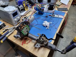
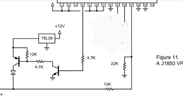
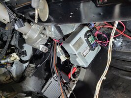
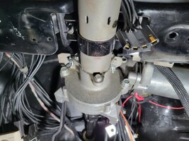
I set off to the salvage yard to pull one of these new-fangled EPS’s from a 2006 Blue Equinox. The hardest part of removing it was removing the airbag from the steering wheel. After that it basically fell out from under the dash. The unit has 3 connectors going to it. One connector has ground and power to the motor and one connector has ground and power to the controller. This power wire goes directly to the battery. The third smaller connector has two tiny wires coming out of it. One of the small wires is a pink wire which takes 12v when the ignition is on, and it tells the unit to come on or go off when the car is turned on and off. This causes a relay inside the unit to click. The second tiny wire is a purple wire and this wire comes from the J1850 transceiver chip inside the EPS controller. This connects to the J1850 bus. You can find a document for the SAE J1850 Bus specification if you want some heavy reading. I found multiple Arduino libraries and examples that talk on a J1850 bus.
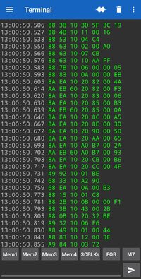
After you grab one of these Arduino libraries/examples and you hook up your Arduino to the purple wire you should start receiving hex codes like the following.
What you’re looking at here is data that’s being sent out over the one wire bus. This data protocol is defined by the SAE J2178 document. There are 4 parts of this document, and you should be able to find all 4 of them on the Internet. You don’t need to purchase the latest copy from SAE. Each line of the data is called a frame and the frame is made up of data in Hex format and 2 characters represents a Byte of data. The first 3 bytes of the frame are defined as the header and depending on that header and the function that is specified in the header, the next several bytes can be defined as the data that goes along with that function. The last byte of the frame is called the CRC byte. Using the SAE2178 documents you will decipher these packets of data and determine what the controller is saying or asking for.
There are two pieces of information that the controller requires to wake up and start providing power assistance to the input shaft of the EPS unit. One is the vehicle speed and two is the request for the status of the engine being on. Using the J2178 documents you will find that the frame of data in the above example (C952300437) contains the second byte Hex 0x52 and is the message from the EPS asking if the engine is on. After looking through the SAE J2178 documents and online resources I discovered that the message/frame (88531184AE) is a valid response to send to the EPS and tell it that the engine is indeed on. The next request from the EPS is the frame (A9283002E0) and that the message from the EPS is asking for the vehicle speed. After looking through the SAE J2178 documents and online resources I discovered that the message (8829110200003B) is a valid response to send to the EPS and tell it that the speed of the vehicle is 0MPH which will provide you with the maximum assistance from the EPS.
After some trial and error, I was able to send these two messages/responses to the EPS using my Arduino and all of a sudden my EPS was alive and working. My plan is to read the data from the speed sending unit that came with my aftermarket gauges and send real time vehicle speed messages to the EPS so that the power assist will lower as the speed of the car increases and the power assist is not needed.
Tip: I had my EPS unit hooked up to a benchtop Power Supply and it would show how many milliamps it was drawing which helps in determining what the controller is doing. You’ll notice the controller before it get’s turned on will hang around 350-380 milliamps and once it turns on you’ll see it jump up into 400 milliamps.
Here are some links to the online resources I relied on and that you may find helpful.
Thanks and happy tinkering!
Great info here with real examples of J2178 data, especially the Google Sheets
ELM327 & Class 2 Serial Data | GMTNation
Good introduction to J2178
Digital Tachometer for Harley Davidson Sportster (Part 3 - Harley Davidson and SAE J1850 VPW) · Momex
CRC page to generate the CRC byte if you choose to create your own responses for your application.
Use for the CRC parametrization option CRC8_SAE_J1850
Sunshine's Homepage - Online CRC Calculator Javascript (sunshine2k.de)
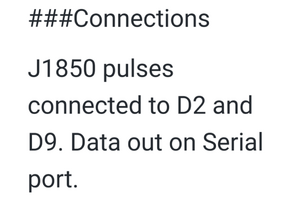
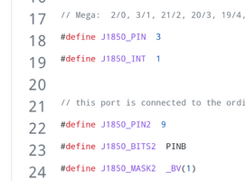
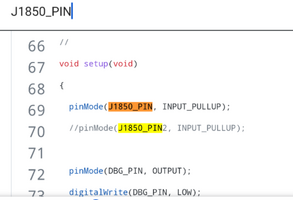
Arduino Code used to capture and transmit data on the J1850 bus
GitHub - matsekberg/j1850decoder: An Arduino based OBD2/J1850 decoder.
GitHub - matsekberg/j1850emitter: Arduino that emits J1850 messages used for testing of j1850decoder
So let me start by saying I stumbled across your forum while searching the internet for any information regarding GM class 2 data network over J1850 bus. You see the rabbit hole I voluntarily threw myself down brought me here. I've victoriously resurfaced and I'm here to share everything I learned so that the next guy/gal who is starting down that hole doesn't have as far to go as I did.
I have a 65 Chevy II SS that I've had the privilege of owning and driving since 1993. Bought from the original owners for $900.00. Since then, she’s had 2 paint jobs and lots of modifications. Right now, she's way back on the back burner because of life and the many kids that I have now. I'm always yearning to get her back on the road, but life seems to be winning that tug-a-war for now. I've always wanted to add power steering to my Nova and since I'm now running a Fat Man Strut conversion kit on her with rack and pinion steering, I really wanted that extra help when maneuvering in tight spaces. I just recently learned of this anomaly called Electric Power Steering which has been available for some time unbeknownst to me. After doing some research I discovered that most of the options out there are manufactured by Koyo Seiko. They basically own the market on Electric Power Steering. So, after looking at all the options of using one from a Toyota model or some other import models. I decided on a model from a 2006 Chevy Equinox. I decided on this model as I had learned that there were ready made solutions available on E-Bay that would allow you to connect to your Equinox EPS unit and wake it up. I’m a tinkerer at heart and if there’s an opportunity for me to achieve a goal and gain knowledge in the process then I’m all for it versus just shelling out the bucks for a solution to be handed to me. I have experience with Arduino so I decided to take the plunge. So here we go.
I set off to the salvage yard to pull one of these new-fangled EPS’s from a 2006 Blue Equinox. The hardest part of removing it was removing the airbag from the steering wheel. After that it basically fell out from under the dash. The unit has 3 connectors going to it. One connector has ground and power to the motor and one connector has ground and power to the controller. This power wire goes directly to the battery. The third smaller connector has two tiny wires coming out of it. One of the small wires is a pink wire which takes 12v when the ignition is on, and it tells the unit to come on or go off when the car is turned on and off. This causes a relay inside the unit to click. The second tiny wire is a purple wire and this wire comes from the J1850 transceiver chip inside the EPS controller. This connects to the J1850 bus. You can find a document for the SAE J1850 Bus specification if you want some heavy reading. I found multiple Arduino libraries and examples that talk on a J1850 bus.
After you grab one of these Arduino libraries/examples and you hook up your Arduino to the purple wire you should start receiving hex codes like the following.
| |||||||
| |||||||
| |||||||
There are two pieces of information that the controller requires to wake up and start providing power assistance to the input shaft of the EPS unit. One is the vehicle speed and two is the request for the status of the engine being on. Using the J2178 documents you will find that the frame of data in the above example (C952300437) contains the second byte Hex 0x52 and is the message from the EPS asking if the engine is on. After looking through the SAE J2178 documents and online resources I discovered that the message/frame (88531184AE) is a valid response to send to the EPS and tell it that the engine is indeed on. The next request from the EPS is the frame (A9283002E0) and that the message from the EPS is asking for the vehicle speed. After looking through the SAE J2178 documents and online resources I discovered that the message (8829110200003B) is a valid response to send to the EPS and tell it that the speed of the vehicle is 0MPH which will provide you with the maximum assistance from the EPS.
After some trial and error, I was able to send these two messages/responses to the EPS using my Arduino and all of a sudden my EPS was alive and working. My plan is to read the data from the speed sending unit that came with my aftermarket gauges and send real time vehicle speed messages to the EPS so that the power assist will lower as the speed of the car increases and the power assist is not needed.
Tip: I had my EPS unit hooked up to a benchtop Power Supply and it would show how many milliamps it was drawing which helps in determining what the controller is doing. You’ll notice the controller before it get’s turned on will hang around 350-380 milliamps and once it turns on you’ll see it jump up into 400 milliamps.
Here are some links to the online resources I relied on and that you may find helpful.
Thanks and happy tinkering!
Great info here with real examples of J2178 data, especially the Google Sheets
ELM327 & Class 2 Serial Data | GMTNation
Good introduction to J2178
Digital Tachometer for Harley Davidson Sportster (Part 3 - Harley Davidson and SAE J1850 VPW) · Momex
CRC page to generate the CRC byte if you choose to create your own responses for your application.
Use for the CRC parametrization option CRC8_SAE_J1850
Sunshine's Homepage - Online CRC Calculator Javascript (sunshine2k.de)
Arduino Code used to capture and transmit data on the J1850 bus
GitHub - matsekberg/j1850decoder: An Arduino based OBD2/J1850 decoder.
GitHub - matsekberg/j1850emitter: Arduino that emits J1850 messages used for testing of j1850decoder

