
Electrical gremlin--ABS and brake warning light on dash

dhanger

Member
Apr 8, 2025
156
Arizona
For the last couple of years or so I've had an occasional gremlin that caused the ABS and parking brake warning lights to come on when first starting the car. When that would happen I could just shut down and restart and all would be fine. Now something related to the HVAC blower has joined the party. Suddenly I lost position 1-4 on the rotary control while position 5 still worked. Wiring diagram shows that position 5 is controlled separately from the others through a relay mounted on the resistor pack. So I set to work troubleshooting the blower, hoping that if I fixed that it would also fix the warning light problem.

After fiddling for a while I found that sometimes 1-4 would work but other times not. That ruled out a blown fuse (#44 in the back seat block). I disconnected the 7 pin connector at the resistor pack, then checked for battery voltage at the correct pins for each position of the rotary switch--they all checked out good so that ruled out a defective rotary control switch. At one point I even lost power on position 5. When that happened I tried rapping on the relay at the resistor pack and was able to get position 5 working. I concluded that the relay at the resistor pack was defective so I replaced the resistor pack thinking I had found the problem. Did not fix it, problem still remains.

These kinds of electrical gremlins are a weak point for me. Can anyone point me to some other troubleshooting? At some point in the past I had replaced the ignition switch but that was not the correct solution either.
 
well your problem with climate is somewhat common. You probably need to observe things more closely as opposed to this works and then doesn't as in this case, powering for the system comes from 2 different sources.... one for high speed and one for the others... IF we are talking about the manual system. My first guess is that you have either a ground issue or power issue. First check would be to ensure that the connector contacts are clean and not burnt looking (a common problem)... or the connector itself is "melted" a bit. Next would be contacts at key elements... the fuses... ensure that the fuses are seated well. Actually, sometimes the posts of the fuse need to be slightly twisted / "spiralled" to ensure contact in the fuse box. The same goes for the relay pins.
 
Yes, it is a manual system as you guessed. There's one key point that I neglected to mention before, the reason that I mentioned the warning lights at the beginning of the post. Trying to run the blower will also activate the warning lights (ABS and parking brake) and most of the time I have to turn off the key completely and let it reset. But resetting the warning lights does not necessarily bring the blower back to life, sometimes yes, sometimes no. But there seems to be some connection between the two, if not directly then remotely somehow.

Fuses--I checked both fuses (35 underhood, 44 rear block) and they were both very tight in their sockets. Of course they were not blown otherwise I wouldn't have any life in their respective circuits but I've proven that's not the case.

Grounds--I know there are several grounding points around the engine block and chassis. It would be nice to know which ground(s) are related so I wouldn't have to spend a lot of time checking unrelated grounds, but I haven't been able to interpret the wiring diagrams to figure that out. The car has been in Arizona forever so there is no corrosion anywhere, I know that's no guarantee that any particular ground has not lost contact but is it safe to assume that it would be low on the priority for troubleshooting?

Edit: Grounds--I did figure out from the HVAC diagram that G201 and G102 are related to the HVAC control, I will locate those and check them. But I don't figure that those are related to the warning light issue so there's still that to figure out. The warning lights don't bother me much right now--as mentioned in my first post that has been an ongoing issue for a couple of years and I can get past that easily. My big priority right now is the blower issue as i need the A/C working for the Arizona summer heat.

Contacts--I have previously removed the HVAC dash control module, disassembled it, then sprayed contact cleaner into the back of the rotary switch (contacts are visible from the back). I have also confirmed that all the contacts around the 7 pin connector to the resistor pack and the 2 pin connector plugged into the blower motor are in good condition--no burns or melting. I had to replace the 2 pin connector about a year ago and everything worked fine until lately.
 
Last edited:
After further searching I learned that G201 splice pack is a common 'gremlin producer'. As soon as I get back to it that's the first thing I'm going to check.
 
Tackled both G102 (under hood) and G201 (splice pack). Disassembled and cleaned up all contact surfaces with a wire brush and added a little dielectric grease. No changes.
 
OK... you have done a lot of good things... but of course, most of this appears to have been done when the things are working. You need to cause a failure condition and be ready, in terms of access and meter to check things out.

Can you be more specific on how you checked for voltage on the rotary speed control as you state that "you have voltage on all the pins going to the resistor pack".... how was this tested. One point that I will make, is that having voltage in these cases of testing does not totally rule things as being good because one needs voltage AND current to successfully drive the subtending circuit (ie. motor). IF the path is too "resistive", then there might not be sufficient current to drive the motor.
 
Related to your "other issue" (ie. abs and brake), those lights aren't powered directly in terms of a "fault condition connects voltage to the indicator". They are set by data communication between the end device and the IP. In this case, the ABS and BCM modules. The "common link", if you will, is that they get their "operating voltages" from a "similar" feed and the hvac system (ie. if you follow the "fusings", they trace back to "run" voltage bus. Of course, there are MANY circuits on the bus... :-( Since you don't appear to be having a totally "fubarred" vehicle, it would appear that potentially those "subfeeds" have an issue at times because you seem to indicate a "on again, off again" issue. In terms of these specific indicators, they could be set by the originating control devices because on startup issue where the power feed is "not quite there"... being to low of voltage or even "too late". The fault could be such that the circuit could "burn thru" any oxide or equivalent and thus start functioning after a time.

Having said that, there can be issues in the fuse block whereby some unlayer tracking is cracked / burnt causing such symptoms. However, at this point, it is probably unwise to go there without doing some checks when the faults / blower issues have occurred to check points to test / confirm things.
 
OK... you have done a lot of good things... but of course, most of this appears to have been done when the things are working. You need to cause a failure condition and be ready, in terms of access and meter to check things out.

Can you be more specific on how you checked for voltage on the rotary speed control as you state that "you have voltage on all the pins going to the resistor pack".... how was this tested. One point that I will make, is that having voltage in these cases of testing does not totally rule things as being good because one needs voltage AND current to successfully drive the subtending circuit (ie. motor). IF the path is too "resistive", then there might not be sufficient current to drive the motor.

Okay, so the first time I ran that test was prior to my first post. Today I ran a modified test on the same connector.

The first time, I tracked down the diagram for the 7 pin connector at the resistor pack, then unplugged the connector. I then used the diagram to match pin 'A-G' with the correct position on the rotary switch. In each case I was getting battery voltage (with a very slight drop compared to directly testing the battery) on the correct pin. That was as far as I went and my conclusion then was that most likely the rotary switch was in good condition.

With today's test I went further. With the connector plugged in I checked to make sure I was not getting any blower movement on position 1-4, then leaving the connector plugged I back probed rotary position 1 at the connector. Initially I got about 2.5V and after a few seconds it settled at about 2.0V. After it settled, out of curiosity, leaving the probe in the same position, I moved the switch through position 2-4. At each successive position the voltage dropped slightly, until at position 4 it was well below 1.0V. Not being an expert at this I have no idea whether those readings have anything to say about my issue; in my mind I wouldn't have expected the voltage to drop so much, and I expected that there would be no voltage while moving through the other rotary switch positions.

Having said that, there can be issues in the fuse block whereby some unlayer tracking is cracked / burnt causing such symptoms. However, at this point, it is probably unwise to go there without doing some checks when the faults / blower issues have occurred to check points to test / confirm things.

Some time ago when the warning light issue first started, and long before the issues I'm having now, I ran into a lot of posts about the not uncommon issue of the copper traces in the fuse block cracking over time. I took my fuse block (under hood) apart to check it out. I placed a high powered microscope in the spindle of my cnc mill, then jogged the fuse block around on the mill table. This made it easy to keep close track of which traces I had completed after marking them. At the time I found no burning or cracks in the traces. Not saying there isn't a problem, just that to the best of my ability I found no issue.
 
  • Like
Reactions: budwich
With today's test I went further. With the connector plugged in I checked to make sure I was not getting any blower movement on position 1-4, then leaving the connector plugged I back probed rotary position 1 at the connector. Initially I got about 2.5V and after a few seconds it settled at about 2.0V. After it settled, out of curiosity, leaving the probe in the same position, I moved the switch through position 2-4. At each successive position the voltage dropped slightly, until at position 4 it was well below 1.0V. Not being an expert at this I have no idea whether those readings have anything to say about my issue; in my mind I wouldn't have expected the voltage to drop so much, and I expected that there would be no voltage while moving through the other rotary switch positions.
can you indicate your "mapping" so we are on the same "page".... ie. rotary position # to connector pin letter. Where were you connecting your ground lead for your meter? The measurements seem strangely low... :-)
 
Readings confirmed: I left the probes where they were (pin B and E), unplugged the connector and turned the blower to position 1. Reading was 11.8V (Battery @12.5V). Plugged the connector back in and voltage dropped back to the 2.0V reading I got earlier.
 
I just realized a flaw in my method--instead of using pin E for grounding, I connected to chassis ground at the G201 ground point I just cleaned up. Still got the same readings.
 
Readings confirmed: I left the probes where they were (pin B and E), unplugged the connector and turned the blower to position 1. Reading was 11.8V (Battery @12.5V). Plugged the connector back in and voltage dropped back to the 2.0V reading I got earlier.
well, that shouldn't happen as the voltage on the B is coming from the "run bus" which can't be pulled that low.... otherwise your truck would stop. Having said that, your key was in "run" for your test... right?
 
well, that shouldn't happen as the voltage on the B is coming from the "run bus" which can't be pulled that low.... otherwise your truck would stop. Having said that, your key was in "run" for your test... right?

Yes.
 
Not sure what to say.... as you have done alot of "checks" and have even "looked" at fuse box layers. IF you look at the circuit diagram, you can see that the "run" in question for this portion of the wiring goes to the hvac and the BCM and Brake Controller. Based on your observations, it is quite likely those two are seeing similar "low voltage" at times.

At this point, my guess is that there is a serious resistance in those route that are causing the drop. I think from your tests, the issue is back from the 7 pin connector... maybe.

Another test that you can try, disconnect the "feed side" connector which feeds the switch. Take a resistance measurement from that pin back towards the ground that you used. Do the measurement for each switch position. They should be "reasonable".
That will then tell you that the issue is likely back from there.

ADDED: during resistance, leave the 7 pin connector connected.
 
Last edited:
Another test that you can try, disconnect the "feed side" connector which feeds the switch.

The rotary switch connector at the back of the hvac control module?

Take a resistance measurement from that pin

Which pin exactly?

back towards the ground that you used. Do the measurement for each switch position. They should be "reasonable".
That will then tell you that the issue is likely back from there.

ADDED: during resistance, leave the 7 pin connector connected.

Can you define what 'reasonable' should be?

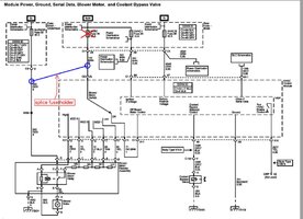
For reference this is the schematic I'm using:

 
Re: @budwich 's observations in Post #7... Since the EBCM is responsive to Power Draws to Ground (G304) during ABS Events... It won't hurt to Check the Ground there for any signs of having either a Broken Wire-Loose Wire-Corrosion where the EBCM Unit is Bolted to the Driver's Side Under Frame adjacent the Driver;s Door:

EBCMGROUND.jpg
 
Thanks, I will check that one.
 
  • Like
Reactions: mrrsm
Which pin exactly?
I screwed up and didn't look at all of the schematic close enough... the "in feeding power" and the outputs to the resistor block are in the same 7 pin connector... :-( thus leaving that connector in place makes it difficult to access the "in feed" power pin (G on the schematic).
Thus you need to be a bit more "sneaky". You have to go to the fuse box, pull fuse 44 on the rear box and do your measurement at that point for the outgoing portion. Hopefully, you can find a ground point close by for the black lead. Hope that makes sense.

NOTE: ensure that you are on the outgoing portion of the fuse socket or you may blow your meter if you are on the voltage side. Of course, you can check that with a quick voltage measurement... checking with both key off and key in run on both the fuse socket points.
 
Found this post, addresses exactly my issue:


As mentioned earlier I replaced the ignition switch when the abs/brake warning issue cropped up way back when (long before my hvac issue came up) but didn't fix the issue. At that time I replaced it with an aftermarket brand (not ACDelco) but since it didn't fix the problem and wasn't causing any other issues I left the aftermarket switch in place. I kept the ACDelco switch just in case.

Now recently (again before the hvac issue) I happened to run across the original switch in a box, decided to take it apart and see if it seemed okay. All the contacts looked good, no burns or pits anywhere, so I put it back together, checked everything with a meter, and put it back in the car, removing the aftermarket switch. I know, probably an exercise in insanity but I was bored I guess. Still was left with the warning light problem.

Now I'm wondering if I should look at this one more time but I'm not sure if there's any point. The ACDelco switch had a gray cover on one side, I learned a while back from @movietvet that the gray cover meant it was an important revision.

Starting to get a little frustrated...haven't forgotten about the latest troubleshooting tips from @budwich but thought I'd throw this out there just in case.
 
  • Like
Reactions: mrrsm and movietvet
Also took a look at G304 as @mrrsm suggested. Appeared that somebody had recently cleaned it up--then I remembered that I had done that a while ago while troubleshooting the problem :duh:
 
  • Like
Reactions: mrrsm and movietvet
Thus you need to be a bit more "sneaky". You have to go to the fuse box, pull fuse 44 on the rear box and do your measurement at that point for the outgoing portion. Hopefully, you can find a ground point close by for the black lead. Hope that makes sense.
Worked on this this morning and pulled some numbers. Found a good ground at the rear fuse box and pulled fuse 44. Put a probe in the outgoing fuse pin and with the resistor pack and motor connector plugged in this is what I got:

Rotary switch position and resistance in ohms:
1--4.0
2--2.5
3--1.7
4--1.4
5--71.3

Position 5 goes through the resistor pack relay coil, don't know if that's reasonable but I'm assuming so since position 5 generally works with no issues.

I'm getting fatigued working on this so for the time being I am thinking of a temporary fix. Weather here is heading into a heat wave with 117F predicted by Saturday. When the weather gets reasonable again I'll come back to it. Generally speaking the blower motor and resistor pack are in working condition, it appears that there is a problem with the circuit being tied in to the run bus via fuse 44. See the attached schematic. If anybody sees a flaw speak up please:

1. Remove fuse 44 for the time being.
2. Splice in a fuse holder between the battery wire at position G on the resistor pack and the input line at the rotary switch. This means that the rotary switch will always be 'live' so I'll have to make sure to manually turn the switch to 0 when leaving the car. I don't anticipate a problem since in this weather we almost never turn the blower down below 3 which is loud enough to hear when shutting off the car.
 

Attachments

  • 2026-07-23_08-53.jpeg
    2026-07-23_08-53.jpeg
    138.8 KB · Views: 5
Looking at my diagram again I see a possible flaw. When the rotary switch is in the off position the circuit gets shunted to the logic system. Not a problem normally since the circuit gets deactivated when the key is not in 'run', but if it's permanently live will that cause a drain over time?
 
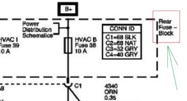
...and since your Upper Right Hand Mechanical Switched HVAC Controller Schematic also refers to some sort of a connection at the Rear Fuse Block... It won't hurt to check on the B-Pillar Ground servicing the BCM-Fuse Block there as well ...just under the Left Rear Passenger Seat on the adjacent Pillar... for a non-corroded Good Ground... You'd be surprised at how corrosive a handful of Cokes spilled under the seat around there can do some Corrosion Mischief:

HVACCONTROL2REARFUSEBLOCK.jpg
 
  • Like
Reactions: dhanger
Rotary switch position and [COLOR=revert-layer] resistance[/COLOR] in ohms:
1--4.0
2--2.5
3--1.7
4--1.4
5--71.3

Position 5 goes through the resistor pack relay coil, don't know if that's reasonable but I'm assuming so since position 5 generally works with no issues.
So.... a couple of things before you take your "sabbatical" on this problem which I understand as you have done a lot.

Earlier you posted about voltage measurements that you did by back probing a position for your voltage reference and then cycled thru the switch position getting some like ~3v going down to ~1v.... which I somewhat misread but it still "funny". Your "setup" should have provided a "good reading" at the "1" position as you would have been reading the voltage drop across ALL of the resistor pack AND the motor. It should have been at or near the "unplugged" voltage which read ~12v earlier. The other voltages that you indicated dropped lower are not really "interpretable" because the resulting "adjusted circuit" (as the switch is moved) has a combination of resistors in between the switched resistor and resistors at the "back probe" point. IF you wanted to do the voltage test again, you would "back probe" the "G" pin / wire at the voltage input.... what you would see then is the "run voltage" and it should not change with switch position.
I am thinking that your "back probing test" is perhaps a "red herring" because it is possible / probable that your "pin" was not in good contact with the conducting surface and thus the reading was not very good.

As for the resistance testing, those appear to be good.... basically one would expect higher resistance at the slowest position as there are more resistor in the path, thus reducing the voltage getting to the motor. As you switch positions, it "drops" a resistor out of the path resulting in higher voltage making it to the motor and thus "more power in". Finally, when you switch to "high", you are sending the "switching voltage" to switch the high speed relay on. The resistance that you read is "high" because it usually does take much current / voltage to operate a relay... if it did, you would be "loading" the overall run circuit for nothing so to speak. IF you do the math on 70 ohm and 12v, you get about .7 amps which isn't much.

What does this prove? Well from a resistance view, it appears the circuit is good. From a voltage / current prospective, its not clear from the tests whether sufficient powering is getting to the motor. Having said that, retesting the motor with direct power and wiring to ensure it operate always... as sometime when a motor is failing, the "start function" doesn't always work and thus it does not turn as perhaps the start current is not sufficient to overcome the "torque resistance" of the motor. Sometimes physically turning the shaft to feel if there is differences in points along the spin path. Sometimes there may be some points where perhaps the fan blades are binding where it stopped causing a later starting issue.
Here is a related portion of an AI response about DC motors and starting... quote: "Voltage Sags: The sudden demand causes temporary drops in supply voltage, which can cause other connected equipment to malfunction or trigger power grid flickers." This seems to potentially allude to your situation with the other circuits "warnings". Of course, this is AI and "generic" so take it for what it is worth... some data point. :-)

AS for your "temporary mod", it may be problem. the "OFF" feed to the controller is for causing operation of the rear hvac system IF you have that option. It would normally see voltage there with key on and nothing with key OFF. It is some sort of "sense" circuit to indicate the "run" status to the control... it probably does draw a lot of current but you can check it with your meter on "current mode" or just put in a switch (cheap toggle switch) to cut the circuit when you turn off your truck.
 
AS for your "temporary mod", it may be problem. the "OFF" feed to the controller is for causing operation of the rear hvac system IF you have that option. It would normally see voltage there with key on and nothing with key OFF. It is some sort of "sense" circuit to indicate the "run" status to the control... it probably does draw a lot of current but you can check it with your meter on "current mode" or just put in a switch (cheap toggle switch) to cut the circuit when you turn off your truck.
I need a little more time to analyze your response although most of it I would characterize as 'same page' :thumbsup:. As for your last paragraph, yeah, I already ordered the fuse holder and a toggle switch as you suggested. This approach is starting to encroach on Rube Goldberg territory which I really hate but for now it's my best solution; along with the heat I've developed some minor medical issues that are slowing me down. I keep waffling over taking it to a shop. For my entire car ownership life I have mostly done my own repairs so handing it over doesn't come easily. I've lived in my current location for 24 years and have never established a comfortable relationship with any shop so the idea gives me the heebie-jeebies LOL.
 
I need a little more time to analyze your response although most of it I would characterize as 'same page' :thumbsup:. As for your last paragraph, yeah, I already ordered the fuse holder and a toggle switch as you suggested. This approach is starting to encroach on Rube Goldberg territory which I really hate but for now it's my best solution; along with the heat I've developed some minor medical issues that are slowing me down. I keep waffling over taking it to a shop. For my entire car ownership life I have mostly done my own repairs so handing it over doesn't come easily. I've lived in my current location for 24 years and have never established a comfortable relationship with any shop so the idea gives me the heebie-jeebies LOL.
The one thing with your "workaround" is that if it works "predictably" ALL TIME... you then have narrowed down the path that are used since you are using the fuse source and the rest of the circuitry.... you are just left with the wiring / fuse box "logistics". Good luck and take care of your self first... your truck won't know any difference one way or the other in terms of repair... but of course, your comfort and sanity will... :-)
 

Forum Statistics

Threads
24,339
Posts
649,448
Members
20,897
Latest member
Hollywood1929

Members Online