- Dec 4, 2011
- 598
The following is how I built my CAI and removed the intake resonator using basic parts from the hardware store. I have a 2004 Trailblazer which uses an IAT sensor. There is no critical placement on these sensors, which simplifies the build. If you have a newer vehicle with a MAF sensor, you will want to look at other discussions for information on how to maintain the original positioning of your MAF sensor.
You want to start with a short straight section of 3" plastic pipe, and a sweeping 90-degree elbow. There are various discussions on whether ABS or PVC is better. I used electrical conduit PVC for the elbow because it had the shape I wanted. I used ABS for the straight sections because I had it on hand. You will also want two rubber 3" pipe couplers. Mine came with a thin metal shield that wrapped around underneath the hose-clamps, but I eventually removed these simply for the aesthetics. And finally, you will need various fittings to reconnect the original hoses... PVC 1/2" MIP to 1/2" barb for the engine vent line; Brass 1/8" MIP to 1/8" barb for the vacuum line; and PVC 90-degree 1" MIP to 1" barb for the large air hose on the underside of the intake. Note that I used a lathe to take down the diameter of the straight pipe for a better fit, but you can achieve the same affect with a dremel, and may not even need to make changes.
To begin, open up the air box, disconnect the intake hose and remove it and the air filter, then remove the intake resonator. None of these parts will be modified, so you can return to stock at any time. This is a great time to clean your throttle body!
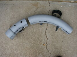
The elbow you purchased should have one side that is that standard 3" diameter, and may have a bulge on the other side to insert another pipe in to. You want to slip one of the rubber couplers half way onto the smaller side, then attach the other side of the coupler to your throttle-body. The other end of the elbow will be pointing out towards the air box. Lay your air filter back in the air box without anything attached to it. You need to eyeball the curve of the elbow, and mark where it is exactly inline with the air filter, rotating the elbow at the throttle-body so that it is in line with the air filter both horizontally as well as vertically. YOU WANT TO TAKE YOUR TIME WITH THIS STEP! In my instance, I could not quite find an alignment I liked, so I used a heat gun to soften the pipe and slightly straighten the curve. It didn't take much, but this got me to a spot where the elbow could exactly face towards the filter. Once you find this point, mark the point across the elbow where you will cut it off.
This shows where I cut my elbow at. Also you can see the change in the bend where I straightened the pipe between the PVC connectors (you are not expected to have your connectors in place yet). I used the scrap piece to drill test holes when I was ready to fit the connectors into this pipe.
View attachment 16944
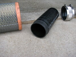
Once you have cleaned up the cut on the elbow, re-attach it to the throttle-body. If you plan on using an aftermarket air filter, place it in the air box, otherwise leave your stock filter sitting there. You want to measure the length of pipe needed to connect the end of the elbow into your filter. Originally I intended to use my stock filter, but the 3" pipe does not fit in place correctly. I used my lathe to turn down the last inch of pipe until it fit the filter. Later I decided to use an aftermarket filter which have clamps for different sizes of intakes, and this was fit to a piece of pipe that had not been modified.
View attachment 16945
You should now be able to attach the second rubber coupling, and assemble the last piece of pipe and the air filter. Make sure the fit is good, and trim up as needed. I didn't like how tight the 3" pipe fit into the opening of the air box, so I put it back on the lathe and trimmed between 1/16" and 1/8" off the overall diameter. This small difference did not affect the fit of the rubber coupling.
View attachment 16946
You are now ready to add the the hose connectors. As said previously, use a piece of scrap pipe to find the right hole sizes to drill. For the PVC connectors, I used spare metal fittings of the same size to cut the threads into the pipe, then wrapped the actual fittings with teflon tape and screwed them into place. The placement is not critical, but you want to locate them relatively near the original locations so that your hoses reach. Your placement may differ from mine, so make sure to check YOUR original intake for the locations where the hoses came from.
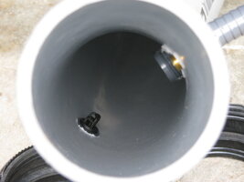
The last piece to attach is your IAT sensor. If you slowly rock it back and forth, it will pop out of the original intake hose. There are no threads on it, it's just a press-fit piece. This makes it relatively easy to fit it into your new intake. I cut a short piece of clear PVC tubing to fit around the sensor, the drilled a hole in the pipe to make a tight fit. There is no strain on this sensor except the weight of its wires, and there will be a vacuum inside the pipe, so you should have no problems with the sensor coming loose. Once the sensor is mounted in the pipe, it should have unrestricted airflow across it.
View attachment 16947
That completes the rebuild of your intake and deletion of the resonator. Hook everything up, and start your vehicle. Close up the air box, and take it out for a drive. You will immediately notice the deeper engine sound when you get on the throttle. After you have confirmed there are no problems, you will want to (reluctantly) disassembly everything, remove your hose fittings, and paint the pipes. Wash and sand both pieces to remove any oil and take off the glazed finish from the pipe. Spray on a good quality primer. When choosing your paint, a textured finish will give it the appearance of factory pieces. I used a flat-black with a gritty texture. After the paint has dried, reinsert the hose connectors, adding black RTV silicon as desired to ensure a good air-tight fit. Here is what my intake looked like with the aftermarket air filter...
View attachment 16948
You are now the proud owner of a custom warm-air intake! You will feel a bit more throttle response, which may improve as the PCM learns the new airflow. This intake will have the same characteristics as the higher-priced aftermarket intake kits, and will fit much better than many of them. If you notice your gas mileage has gone down, you are enjoying the extra power too much and need to get your foot off the gas. I have been driving with this mod for over a year now, and never once had any problems with the IAT coming loose, or the pipe connectors coming apart.
For more and larger pictures, click here.
After building this mod, you may wish to continue on and create a true cold-air intake...
You want to start with a short straight section of 3" plastic pipe, and a sweeping 90-degree elbow. There are various discussions on whether ABS or PVC is better. I used electrical conduit PVC for the elbow because it had the shape I wanted. I used ABS for the straight sections because I had it on hand. You will also want two rubber 3" pipe couplers. Mine came with a thin metal shield that wrapped around underneath the hose-clamps, but I eventually removed these simply for the aesthetics. And finally, you will need various fittings to reconnect the original hoses... PVC 1/2" MIP to 1/2" barb for the engine vent line; Brass 1/8" MIP to 1/8" barb for the vacuum line; and PVC 90-degree 1" MIP to 1" barb for the large air hose on the underside of the intake. Note that I used a lathe to take down the diameter of the straight pipe for a better fit, but you can achieve the same affect with a dremel, and may not even need to make changes.
To begin, open up the air box, disconnect the intake hose and remove it and the air filter, then remove the intake resonator. None of these parts will be modified, so you can return to stock at any time. This is a great time to clean your throttle body!
The elbow you purchased should have one side that is that standard 3" diameter, and may have a bulge on the other side to insert another pipe in to. You want to slip one of the rubber couplers half way onto the smaller side, then attach the other side of the coupler to your throttle-body. The other end of the elbow will be pointing out towards the air box. Lay your air filter back in the air box without anything attached to it. You need to eyeball the curve of the elbow, and mark where it is exactly inline with the air filter, rotating the elbow at the throttle-body so that it is in line with the air filter both horizontally as well as vertically. YOU WANT TO TAKE YOUR TIME WITH THIS STEP! In my instance, I could not quite find an alignment I liked, so I used a heat gun to soften the pipe and slightly straighten the curve. It didn't take much, but this got me to a spot where the elbow could exactly face towards the filter. Once you find this point, mark the point across the elbow where you will cut it off.
This shows where I cut my elbow at. Also you can see the change in the bend where I straightened the pipe between the PVC connectors (you are not expected to have your connectors in place yet). I used the scrap piece to drill test holes when I was ready to fit the connectors into this pipe.
View attachment 16944
Once you have cleaned up the cut on the elbow, re-attach it to the throttle-body. If you plan on using an aftermarket air filter, place it in the air box, otherwise leave your stock filter sitting there. You want to measure the length of pipe needed to connect the end of the elbow into your filter. Originally I intended to use my stock filter, but the 3" pipe does not fit in place correctly. I used my lathe to turn down the last inch of pipe until it fit the filter. Later I decided to use an aftermarket filter which have clamps for different sizes of intakes, and this was fit to a piece of pipe that had not been modified.
View attachment 16945
You should now be able to attach the second rubber coupling, and assemble the last piece of pipe and the air filter. Make sure the fit is good, and trim up as needed. I didn't like how tight the 3" pipe fit into the opening of the air box, so I put it back on the lathe and trimmed between 1/16" and 1/8" off the overall diameter. This small difference did not affect the fit of the rubber coupling.
View attachment 16946
You are now ready to add the the hose connectors. As said previously, use a piece of scrap pipe to find the right hole sizes to drill. For the PVC connectors, I used spare metal fittings of the same size to cut the threads into the pipe, then wrapped the actual fittings with teflon tape and screwed them into place. The placement is not critical, but you want to locate them relatively near the original locations so that your hoses reach. Your placement may differ from mine, so make sure to check YOUR original intake for the locations where the hoses came from.
The last piece to attach is your IAT sensor. If you slowly rock it back and forth, it will pop out of the original intake hose. There are no threads on it, it's just a press-fit piece. This makes it relatively easy to fit it into your new intake. I cut a short piece of clear PVC tubing to fit around the sensor, the drilled a hole in the pipe to make a tight fit. There is no strain on this sensor except the weight of its wires, and there will be a vacuum inside the pipe, so you should have no problems with the sensor coming loose. Once the sensor is mounted in the pipe, it should have unrestricted airflow across it.
View attachment 16947
That completes the rebuild of your intake and deletion of the resonator. Hook everything up, and start your vehicle. Close up the air box, and take it out for a drive. You will immediately notice the deeper engine sound when you get on the throttle. After you have confirmed there are no problems, you will want to (reluctantly) disassembly everything, remove your hose fittings, and paint the pipes. Wash and sand both pieces to remove any oil and take off the glazed finish from the pipe. Spray on a good quality primer. When choosing your paint, a textured finish will give it the appearance of factory pieces. I used a flat-black with a gritty texture. After the paint has dried, reinsert the hose connectors, adding black RTV silicon as desired to ensure a good air-tight fit. Here is what my intake looked like with the aftermarket air filter...
View attachment 16948
You are now the proud owner of a custom warm-air intake! You will feel a bit more throttle response, which may improve as the PCM learns the new airflow. This intake will have the same characteristics as the higher-priced aftermarket intake kits, and will fit much better than many of them. If you notice your gas mileage has gone down, you are enjoying the extra power too much and need to get your foot off the gas.
 I have been driving with this mod for over a year now, and never once had any problems with the IAT coming loose, or the pipe connectors coming apart.
For more and larger pictures, click here.
After building this mod, you may wish to continue on and create a true cold-air intake...

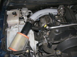
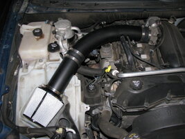

 Looks good, but now especially in the summer you have to make something to keep the heat away. Gut the airbox and run some ducting to it, Saw a thread on the OS.
 The picture was just taken to clearly show the components. I did state in the article that you should reassemble the air-box before driving it. I was just trying to get up an article on one method of building a custom intake and remove the resonator, without having to spend a couple hundred bucks on something from ebay that doesn't even fit.


