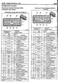
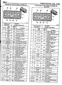
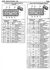
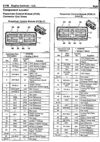
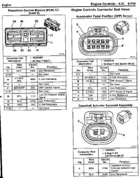
BCM pinout

stickypoop

Original poster
Member
Oct 14, 2014
872
Looking to pick up on the reverse lamp circuit at the BCM. I've found sources that indicate it may be a light green wire, but there are several of them back there. One of which is a com wire that didn't take kindly to having a test light on it...

anyone have a pinout for the connectors or a better idea of what wire to go after?

2004 Envoy
 

mrrsm

Lifetime VIP Donor
Supporting Donor
Member
Oct 22, 2015
8,192
Tampa Bay Area
I know these are for the V8 Flavors ...So let me know if you find that these coincide with your Year-Make-Model and whether or not they are useful.I want to add this in with the PCM Pinouts and put all of these images in one future post:

http://tbssowners.com/docs/BCM_Connector_End_Views.pdf
 
  • Like
Reactions: stickypoop

stickypoop

Original poster
Member
Oct 14, 2014
872
Very useful, thanks! It would appear the connection I was searching for is actually a ribbon cable. The business end of that would be buried into the box... looks like I'll be tapping into a wire on the exterior after all. :duh:
 

mrrsm

Lifetime VIP Donor
Supporting Donor
Member
Oct 22, 2015
8,192
Tampa Bay Area
Cool Beenz... I might as well drop the rest of the PCM PINOUT Images here. This way... Your Post will be the FTW On Topic Posting for the subject and will attract other interested Members as well...

(Lurkers are ALWAYS Welcome at GMT Nation, Too)... :>).

upload_2017-4-25_20-33-51.pngupload_2017-4-25_20-34-21.pngupload_2017-4-25_20-34-43.pngupload_2017-4-25_20-37-25.png2004trailblazerpcm4-jpg.73337.jpeg
 
Last edited:
  • Like
Reactions: stickypoop

XUVconversion

Member
Aug 6, 2018
9
Southern CALIFORNIA
Looking for BCM info for my 04 XUV. Specifically which connector to separate and jump pins, looking to trigger gate latches, manually move roof.

Dealer was going to do a TechII test overriding sensors, no luck, refunded my $130.00 (nice!)

Learned tail gate window sensor showing window 1/2 way up but is stuck full down.

Roof in 80-90% closed position. Beyond tailgate window motor being shot no known reason the latches, roof should not work.

A way to fool BCM into full up would be cool to start with and see.

Since that part isn't made I'm likely never trying to replace it. I need a truck and would like the gate to drop for sure. Roof to slide open too.

Otherwise I'll end up removing tail glass and roof completely for now and just work on the gate....

Thank you in advanced.
 

mrrsm

Lifetime VIP Donor
Supporting Donor
Member
Oct 22, 2015
8,192
Tampa Bay Area
When time permits... have look at the images included in Post #26 at this Link to consider investigating "The Umbilicus" that necks through the Hinge Area of the Tailgate by pulling the Grommet(s) free and searching for any Pulled, Stretched or Broken Wires. Perhaps the problem lies there ...and not with any of the other gear that seems to be creating the intermittent issues.

The Wiring within that Bundle not only includes Power Positive and Ground Wires... but also Class 2 Wiring as well... and if any of the Modules serviced through that 'conduit' have any breaks or damage... the adjacent Modules and Motors may suffer as a result:

https://gmtnation.com/forums/thread...repaired-instrument-cluster.18272/post-554794
 
  • Like
Reactions: XUVconversion

XUVconversion

Member
Aug 6, 2018
9
Southern CALIFORNIA
Yep probably. Inspection of wires done. Switch contacts at overhead console appear new. wires checked from there back are good. I have the obligatory rear window defog connectors hanging back there. No connector or wiring issues found after thorough inspection otherwise. Moving on from tailgate to ROOF motor. Hoping to find pin nuber / wire color to ground and see my ROOF close. Will check out your link thank you!

Scoured the info. I see it's related to a standard Envoy with Lift Gate LFG. Great info! However XUV specific info sought. Someday I wanted to get a China Tech II scannner, looks like that is a PITA to work with.
 
Last edited:

mrrsm

Lifetime VIP Donor
Supporting Donor
Member
Oct 22, 2015
8,192
Tampa Bay Area
If you are Standing at the 'The Gates of GM Module Hell'.... even if you slip, fall and get stuck for a while down inside that Purgatory... The ONLY inexpensive way out of there ...is by getting your hands on a "GMYKO" Tech2 Scanner so you can Ping and See which (or Test All at once) Modules are on the Databus Single Wire Network and functioning... and which are acting up. Visit this link if you become serious about getting the Complete Tech 2 Clone Kit for $330.00 and maybe $10-$15 more for the "HWK" (Hard Ware Key):

https://gmtnation.com/forums/threads/new-complete-kit-gymko-gm-tech-ii-scan-tool.17878/post-556060
 
  • Like
Reactions: XUVconversion

mrrsm

Lifetime VIP Donor
Supporting Donor
Member
Oct 22, 2015
8,192
Tampa Bay Area
Yes... I can see what you mean about how different in the "X"treme your vehicle Electro-Mechanical apparatus is ...as shown in this video:


Perhaps the solution can be found by pulling that overhead Push-Button Console and checking just the Button Contacts related to the Overhead Latch-Motor for Color and Continuity when being actuated. Never having seen this unique set-up before... it would be interesting to know if all of the wiring works strictly on (12) Volts with Body Grounds that sidesteps any interface with the PCM entirely.

If the apparatus can function with the Key/On in the Accessory Position without the Engine running, side-stepping the PCM-BCM ... then there might be simpler solution to be found for the Latching-Un-Latching issue. Perhaps this would explain why there are no Wiring Diagrams available that show the PCM-BCM stuff ... if there are none.
 
  • Like
Reactions: XUVconversion

budwich

Member
Jun 16, 2013
2,173
kanata
not sure that I know / follow this but maybe this schematic for the "roof" is what you are looking for... maybe.
 

Attachments

  • power roof 2004.pdf
    172 KB · Views: 52
  • Like
Reactions: XUVconversion

XUVconversion

Member
Aug 6, 2018
9
Southern CALIFORNIA
Thank you! buwich... Appears the the power roof module just sends 12v to the BLUE for open and PURPLE for closed. Surprised we're not grounding a signal line as done with the tailgate window tap.

Thank you! MRRSM, I thinnk I'm ready to move on to the Tech II clone. Thank you for that link, checking it out now.

NOTE: I too wondered about the contacts on that membrane switch in the ceiling console. IT'S ONE MOTHERBOARD (not three separate switches). Already checked it out. The roof contacts show only the faintest hint of wear, the endgate glass contacts looked virtually unused. I took a little steel wool to the ONLY working button, the midgate limo window, that looked nasty. Works perfectly though. It's inability to enter re-learn (close or open roof in DIC) is the real issue.
 
  • Like
Reactions: LovingmyXUV

mrrsm

Lifetime VIP Donor
Supporting Donor
Member
Oct 22, 2015
8,192
Tampa Bay Area
Okay… This Information looks very promising and interesting:

THIS Link leads to a discussion of the GMC XUV Electro-Mechanical Windows and Lift-gate(?) Latch Locking and Release Operational Problems:

https://www.justanswer.com/gm/6leb7-manually-release-mid-gate-2004-gmc-envoy-xuv.html

..and THIS is a GMC XUV Wiring Diagram worth Downloading that may be precisely what you have been looking for... and can be much better interpreted by @budwich than yours truly:

http://ww2.justanswer.com/uploads/jettadan1/2012-05-01_022134_fullshot.pdf

...and if it comes down to cases and you need a Replacement Overhead Switch Console, there is one here on eBay:

https://www.ebay.com/sch/i.html?_from=R40&_trksid=m570.l1313&_nkw=gmc+xuv+overhead+switch&_sacat=0
 
  • Like
Reactions: XUVconversion

budwich

Member
Jun 16, 2013
2,173
kanata
Thank you! buwich... Appears the the power roof module just sends 12v to the BLUE for open and PURPLE for closed. Surprised we're not grounding a signal line as done with the tailgate window tap.

Thank you! MRRSM, I thinnk I'm ready to move on to the Tech II clone. Thank you for that link, checking it out now.

NOTE: I too wondered about the contacts on that membrane switch in the ceiling console. IT'S ONE MOTHERBOARD (not three separate switches). Already checked it out. The roof contacts show only the faintest hint of wear, the endgate glass contacts looked virtually unused. I took a little steel wool to the ONLY working button, the midgate limo window, that looked nasty. Works perfectly though. It's inability to enter re-learn (close or open roof in DIC) is the real issue.
I think you misunderstood the pdf that I posted.... maybe.
Look closer at the diagram... you will see that the system indeed grounds or powers the motor accordingly. Its is the "standard flip"... basically the controller puts power on one lead and grounds the other to go in one direction and reverses the operation to go in the other.... So basically that's all you have to do to get the motor to move... assuming that the track system is indeed "good". Nothing really "mystical". Of course, you need to look closer at the system mechanicals to see why it is in its current state... there IS a ROOT cause for your problem.
 
  • Like
Reactions: XUVconversion

mrrsm

Lifetime VIP Donor
Supporting Donor
Member
Oct 22, 2015
8,192
Tampa Bay Area
The attached PDF contains a Complete List of the Pin-Out Definitions for ALL Three Connectors for the GMT360 BCM to Rear Fuse Box Interfaces:

The Conventions are as Follows:

BCM C#
GM OEM Connector Part Number and Pin Tray Data
Pin Alpha-Numeric Name
Wire Color Combo
Circuit Number
Functions Defined

Body Control Module (BCM) C1


Connector Part Information
OEM: 12110088
Service: 15306210
Description: 24-Way F Micro-Pack 100 Series (GY)
Terminal Part Information
Pins: A2, A3, A4, A5, A6, A12, B1, B2, B3, B4, B5, B6, B7, B8, B9, B10, B11, B12
Terminal/Tray: 12146447/3
Core/Insulation Crimp: E/C
Release Tool/Test Probe: 12031876-1/J-35616-6 (BN)

Body Control Module (BCM) C1
Pin Wire Color Circuit No. Function


A1---- Not Used
A2 WH 2282 Headlamp Washer Relay Control (CE4)
A3 OG 1140 Battery Positive Voltage
A4 BK/WH 1969 Headlamp High Beam Relay Control
A5 PK/WH 1970 Headlamp Low Beam Relay Control
A6 PK 5363 Inclination Sensor Low Reference (BAE)
A7-A11 ---- Not Used
A12 WH 278 Ambient Light Sensor Signal
B1 L-GN 1037 Class 2 Serial Data
B2 BK 279 Ambient Light Sensor Low Reference
B3 L-GN 2270 Rear Window Washer Relay Control
B4 GY/BK 2226 Instrument Panel Lamps Dimmer Switch Low Reference
B5 GY 705 5-Volt Reference
B6 WH 2283 12-Volt Reference
B7 OG/BK 2090 Courtesy Lamps Supply Voltage
B8 L-GN 1011 Remote Radio Control Signal (STW)
B9 GY391 Rear Window Wiper Switch Signal
B10 YE 1836 Security System Sensor Signal
B11 GY 2521 Right Sunload Sensor Signal (CJ2)
B12 L-BU/BK 2519 Left Sunload Sensor Signal (CJ2)

Body Control Module (BCM) C2
Pin Wire Color Circuit No. Function


Connector Part Information
OEM: 12110112
Service: 12110112
Description: 32-Way F Micro-Pack 100 Series (TN)
Terminal Part Information
Pins: E3, E4, E5, E6, E7, E8, E9, E11, E12, E14, F3, F4, F5, F6, F7, F8, F9, F10, F11, F13
Terminal/Tray: 12146447/3
Core/Insulation Crimp: E/C
Release Tool/Test Probe: 12031876-1/J-35616-6 (BN)

Body Control Module (BCM) C2
Pin Wire Color Circuit No. Function


E1-E2 ---- Not Used
E3 L-GN 80 Key In Ignition Switch Signal
E4 YE 307 Headlamp Switch Flash to Pass Signal
E5 GY/BK 308 Park Lamp Switch On Signal
E6 PK/BK 109 Hood Ajar Switch Signal (UA2)
E7 PK 1348 Headlamp On Indicator Control
E8 BK 1835 Security System Sensor Low Reference
E9 RD/WH 812 12-Volt Reference
E10 ---- Not Used
E11 D-GN/WH 1317 Fog Lamp Relay and Indicator Control (T96)
E12 BK 28 Horn Relay Control
E13 ---- Not Used
E14 TN 5463 Daytime Running Lamp Override Indicator
E15-E16 ---- Not Used
F1-F2 ---- Not Used
F3 D-GN 113 Windshield Wiper Switch Signal 2
F4 D-BU/WH 1495 Courtesy Lamps On Signal
F5 BN/WH 1871 Headlamp Washer Switch Signal (CE4)
F6 OG 192 Front Fog Lamps Switch Signal (T96)
F7 L-BU 187 Rear Fog Lamps Switch Signal (T79)
F8 L-GN 5462 DRL Defeat Switch Signal
F9 WH 103 Headlamp Switch Headlamps On Signal
F10 L-GN 11 Headlamp High Beam Supply Voltage
F11 PU 328 Interior Lamp Defeat Switch Signal
F12 ---- Not Used
F13 PK 5068 Intrusion Sensor Switch Disable Signal (BAE)
F14-F16 ---- Not Used

Body Control Module (BCM) C3
Pin Wire Color Circuit No. Function


Connector Part Information
OEM: 15354796
Service: See Catalog
Description: 40-Way F Printed Circuit Flexible (GY)
Terminal Part Information
Pins: A1, A2, A3, A4, A5, A6, A8, A11, A12, A13, A14, A15, A16, A18, A19, A20, B1, B2, B3, B4, B5, B6, B7, B8, B9, B11, B12, B13, B14, B15, B17, B18, B19, B20
Terminal/Tray: See Terminal Repair Kit
Core/Insulation Crimp: See Terminal Repair Kit
Release Tool/Test Probe: See Terminal Repair Kit

Body Control Module (BCM) C3
Pin Wire Color Circuit No. Function


A1 -- 2140 Battery Positive Voltage
A2 – 2140 Battery Positive Voltage
A3 – 748 Right Rear Door Ajar Switch Signal
A4 – 1134 Park Brake Switch Signal
A5 – 195 Door Lock Control
A6 – 2265 Power Window Lockout Left Rear Control
A7 ---- Not Used
A8 – 747 Left Rear Door Ajar Switch Signal
A9- A10 ---- Not Used
A11 – 1350 Ground
A12 – 1353 RAP Supply Voltage
A13 – 194 Door Unlock Control
A14 – 1080 Park Lamp Relay Control
A15 – 5168 Power Sounder Enable Signal (BAE)
A16 – 5204 Intrusion Sensor Data Signal (BAE)
A17 ---- Not Used
A18 – 992 Ignition 0 Voltage
A19 – 39 Ignition 1 Voltage
A20 – 541 Ignition 3 Voltage
B1 – 230 Instrument Panel Lamps Dimming Control
B2 – 230 Instrument Panel Lamps Dimming Control
B3 – 690 Courtesy Lamp Supply Voltage
B4 – 2240 Battery Positive Voltage
B5 – 1186 Power Window Switch Right Rear Up Signal
B6 – 2266 Power Window Lockout Right Rear Control
B7 – 1188 Power Window Switch Right Rear Down Signal
B8 – 1185 Power Window Switch Left Rear Up Signal
B9 – 1187 Power Window Switch Left Rear Down Signal
B10 ---- Not Used
B11 – 1350 Ground
B12 – 24 Backup Lamp Supply Voltage
B13 – 4440 Battery Positive Voltage
B14 – 1382 LED Dimming Signal
B15 – 543 Accessory Voltage
B16 ---- Not Used
B17 – 4040 Battery Positive Voltage
B18 – 1732 Courtesy Lamps Supply Voltage
B19 – 1977 Rear Fog Lamp Relay and Indicator Control
B20 – 5362 Incline Sensor Signal (BAE)


Prepared by @mrrsm for www.gmtnation.com on 05/29/2024
 

Attachments

  • BCMALLPINOUTDATA.pdf
    33 KB · Views: 6
Last edited:

Forum Statistics

Threads
23,664
Posts
641,765
Members
19,091
Latest member
marcinkit

Members Online

No members online now.