jimmyjam said:
Sorry I never got back on this. Just crossed my mind just now.
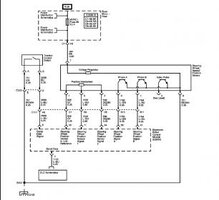
The EBCM receives +B. According to the schematics (2006 wiring, page 13) it provides a +5V reference for the yaw sensor, and a +5V reference for the steering wheel position sensor. The steering wheel sensor also has its own power source through fuse HVAC1, but appears to get its reference voltage for readings to the EBCM from the EBCM module. There is no direct link between the steering wheel sensor and the yaw sensor, and it would make no sense to pass a reference through the EBCM just to get over to the yaw sensor. Plus the EBCM already has a lead (Pin 25, Gray wire) feeding a reference signal TO the steering wheel sensor.
That's where I've come up with the EBCM containing the regulator(s). It receives +12 and spits out two different outputs (the one above, and pin 23 dark green) that are both +5V and provides low references for both of those. Generally whichever module is going to need a particular voltage for reference is going to be the one which provides that voltage locally to the sensors, such as the PCM providing the +5V leads for engine-related sensors, though there are times in some vehicles where setups run against this convention.
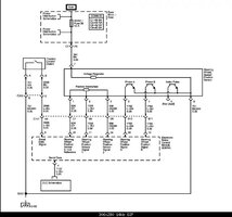
Notice the flow of wiring in the diagram you provided. The regulator within the steering wheel sensor is connected to two parts with a third one unused. There is also a second sensor setup that also has dual sensors. The steering wheel sensor provides measurements of both the actual position of the wheel (two sensors for correlation check), and steering wheel speed sensors (how fast you're turning the wheel, and two sensors for correlation). The wheel position sensor is the one getting +5v from the EBCM as it's easy to say locked-left is 0 volts and locked-right is 5 volts.
The two attached to the regulator are the speed sensors, which produce an output between 0 and whatever the regulator provides (probably 5, maybe another number) depending on how fast the wheel is being turned. This system is likely designed to anticipate what the driver is doing, such as freaking out and whipping the wheel in a particular direction, in an attempt to better retain control of the vehicle. Turning the wheel slowly would probably induce pitiful voltages at the outputs, like say 0.1 volts, while moderate turning may produce say 2.5 volts. It's kind of like having a small crank-up generator attached to a light bulb, the faster you crank the brighter the bulb gets.
I don't mean to try sounding condescending or like some d-bag professor at an Ivy League school, I'm just trying to elaborate on my understanding of the system so that others may better understand it too, just in case they're curious.