Hello. I am brand new. I didn't see this answered anywhere. I have seen lots of useful information about Trailblazers on this site, and I appreciate all of the valuable information. A few weeks ago I picked up a very clean 2002 Trailblazer with a bad engine. Apparently it was run dry and spun a rod bearing. The rest of the bearings weren't very good either. Anyway I am rebuilding it. The crank kit arrived and I realized you can put the main bearings in with the tangs going either direction in the bearing caps. Which way do they go? Should the top go the same direction as the bottom so the tangs are opposite, or the same side? I realize the caps are numbered and arrow goes forward. I just don't know about the bearing direction. I appreciate any help.
You are using an out of date browser. It may not display this or other websites correctly.
You should upgrade or use an alternative browser.
You should upgrade or use an alternative browser.
Which way do the main bearings go on 4.2?
- Thread starter KWG2005
- Start date
Welcome to GMT Nation...
If you are VERY Clever... you will consider an alternative approach by purchasing a Decent, Fully Dressed, Intact Engine from a Local Salvage Yard instead ... preferably one that has come out of a Running Vehicle that was disabled in an Accident that did NOT involve Engine Compartment Damage or extreme damage from any Head On Collision.
However... If you are Bound and Determined to proceed... EVERYTHING you read from this point on is meant for your Education and Edification and should NOT be taken in any pejorative sense and neither meant to be insulting nor injurious to your Mechanical Sensibilities.
If You Widen Your Gaze... In Time... You Will Learn to Appreciate THIS Information:
(1) Re-Building ANY GM Atlas Vortec 4200 LL8 Engine is a LONG & EXPENSIVE Road ...with NO Turns.
(2) Visit THIS link and look over All Four Pages of the Requisite New Engine Parts Listings I have meticulously Photo-Documented along with Descriptions of the Majority of the OEM Parts needed for a Complete Atlas Engine Rebuild.

 www.flickr.com
(3) View THESE attached Engine Dis-Assembly Images .. .and pay particular attention to the One Image Below that shows the position of the Slotted Main Crankshaft Bearings in relation to the presence of the Lateral (Passenger Side) Oil Journal via the Bi-Direction High-Lighting Red Arrows to help you understand the proper location of these GM OEM Aluminum - Silicate Babbitt Bearings Slot and Tang Placement, Refer to the Exploded Engine Component Diagram for some Additional Orientation:


(4) Before proceeding any further...Take the necessary Time and Effort to COMPLETELY Memorialize EVERY Single Engine Part, their Locations and Appearance and their Positions, along with Every Aspect of your Motor. Not doing so will follow on with suffering some extreme regret when you realize that it is impossible to maintain a PERFECT Institutional Memory of EVERY SINGLE COMPONENT involved with this Engine when it comes time later on to Do The Complete Rebuild... Correctly. There is NOTHING too trivial to make a decent photo-record of in advance...Before---During-- and After ...you proceed Into and Out of this Motor.
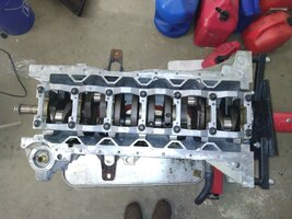
Here are some additional Views of the Main Bearing Locations inside the Upper Block (observe that the Cleaned Engine is INVERTED on an Engine Stand:


These are the GM OEM Main Bearing and Connecting Rod Bearing Kits required AFTER ensuring that a Qualified Machine Shop has Measured the Block Journals for any Spun Bearing Damage.. .and performed a Line Boring for correcting this Critical Damage.


If you are VERY Clever... you will consider an alternative approach by purchasing a Decent, Fully Dressed, Intact Engine from a Local Salvage Yard instead ... preferably one that has come out of a Running Vehicle that was disabled in an Accident that did NOT involve Engine Compartment Damage or extreme damage from any Head On Collision.
However... If you are Bound and Determined to proceed... EVERYTHING you read from this point on is meant for your Education and Edification and should NOT be taken in any pejorative sense and neither meant to be insulting nor injurious to your Mechanical Sensibilities.
If You Widen Your Gaze... In Time... You Will Learn to Appreciate THIS Information:
(1) Re-Building ANY GM Atlas Vortec 4200 LL8 Engine is a LONG & EXPENSIVE Road ...with NO Turns.
(2) Visit THIS link and look over All Four Pages of the Requisite New Engine Parts Listings I have meticulously Photo-Documented along with Descriptions of the Majority of the OEM Parts needed for a Complete Atlas Engine Rebuild.
GM_04_42L_NEW_ENGINE_PARTS
This Album contains images of Brand New Engine Parts and Components for the Complete Rebuild of the GM Atlas LL8 4.2L Engine for the years 2002-2004.
www.flickr.com
(3) View THESE attached Engine Dis-Assembly Images .. .and pay particular attention to the One Image Below that shows the position of the Slotted Main Crankshaft Bearings in relation to the presence of the Lateral (Passenger Side) Oil Journal via the Bi-Direction High-Lighting Red Arrows to help you understand the proper location of these GM OEM Aluminum - Silicate Babbitt Bearings Slot and Tang Placement, Refer to the Exploded Engine Component Diagram for some Additional Orientation:
(4) Before proceeding any further...Take the necessary Time and Effort to COMPLETELY Memorialize EVERY Single Engine Part, their Locations and Appearance and their Positions, along with Every Aspect of your Motor. Not doing so will follow on with suffering some extreme regret when you realize that it is impossible to maintain a PERFECT Institutional Memory of EVERY SINGLE COMPONENT involved with this Engine when it comes time later on to Do The Complete Rebuild... Correctly. There is NOTHING too trivial to make a decent photo-record of in advance...Before---During-- and After ...you proceed Into and Out of this Motor.
Here are some additional Views of the Main Bearing Locations inside the Upper Block (observe that the Cleaned Engine is INVERTED on an Engine Stand:
These are the GM OEM Main Bearing and Connecting Rod Bearing Kits required AFTER ensuring that a Qualified Machine Shop has Measured the Block Journals for any Spun Bearing Damage.. .and performed a Line Boring for correcting this Critical Damage.
Last edited:

Thanks for your reply. So far I have only seen that the upper half of the main bearing must be inserted so the oil hole lines up with the hole in the block. That is pretty obvious, otherwise the bearing would get no oil. The lower half is what I'm concerned with. There is a slot for the tang on both sides of the bearing caps, so the lower half can go either way. I just don't recall which way it came off. I took a lot of pictures, but this engine was so neglected that everything was black with burned oil sludge so these particular images are useless. I'll double check them and my notes, but I'm 98 percent sure I don't have that info. I'm surprised the factory service manuals don't say which way they go. I sent an email to enginetech, hopefully they will reply, but I figured I would ask the forum here since I have been very impressed with the information on this site.
Please forgive all the prior mentioned generalities... The more precise information is shown below in these additional images. The Main Caps (in addition to being held in place with a Galvanized Steel Cradle and a Stack of Thin, TTY Cap Screws (Bolts)... have markings centered atop each Cap as Laser DOT Matrix Etched In Numbers... 1-7 ... designating their Correct Order of Installation from Front to Back along with Etched In Arrows indicating their Correct Facing Direction towards the Front of the Engine Block.
A "GROT" (Good Rule Of Thumb) to Follow... would be to First Establish the Direction of Crankshaft Rotation (Counter-Clockwise in ALL GM Motors when Viewed Facing the Front of the Engine Compartment) and then insert the Main Bearings' Tangs opposite each other such that they would RESIST being grabbed by the Spinning Crankshaft Journals (...at each Notch Location, either in the Aluminum Block or within each Main Cap) via VERY Close Tolerances, breaking loose and then spinning around like crazy inside of the Block Journals... just before Destroying the Motor.
The Insert Positions for the Main Bearing Tangs should be such... that when the GM Atlas LL8 4.2L Engine Block is INVERTED on the Engine Stand, once you are positioned standing at the BACK of the Motor looking forward towards the FRONT of the Block, insert the Upper Halves of the Main Bearings with the Tangs fitted into the RIGHT HAND SIDE of the Upper (INVERTED) Engine.
Likewise ...with the Main Cap(s) Held in Your Hand...and with it Facing Right Side Up and with the Numbers and Arrows oriented Facing towards the FRONT of the Motor... FLIP IT UPSIDE DOWN and then insert the Lower Bearing Halves with the Bearing Tang(s) oriented into the LEFT HAND SIDE of the Main Cap(s). These additional Photos will give the right guidance to Engine Builders when viewed with the others included above:


This is a Related "On Topic" Thread with some additional information on The Mains and Con-Rod TTY Fasteners:
 gmtnation.com
A "GROT" (Good Rule Of Thumb) to Follow... would be to First Establish the Direction of Crankshaft Rotation (Counter-Clockwise in ALL GM Motors when Viewed Facing the Front of the Engine Compartment) and then insert the Main Bearings' Tangs opposite each other such that they would RESIST being grabbed by the Spinning Crankshaft Journals (...at each Notch Location, either in the Aluminum Block or within each Main Cap) via VERY Close Tolerances, breaking loose and then spinning around like crazy inside of the Block Journals... just before Destroying the Motor.
The Insert Positions for the Main Bearing Tangs should be such... that when the GM Atlas LL8 4.2L Engine Block is INVERTED on the Engine Stand, once you are positioned standing at the BACK of the Motor looking forward towards the FRONT of the Block, insert the Upper Halves of the Main Bearings with the Tangs fitted into the RIGHT HAND SIDE of the Upper (INVERTED) Engine.
Likewise ...with the Main Cap(s) Held in Your Hand...and with it Facing Right Side Up and with the Numbers and Arrows oriented Facing towards the FRONT of the Motor... FLIP IT UPSIDE DOWN and then insert the Lower Bearing Halves with the Bearing Tang(s) oriented into the LEFT HAND SIDE of the Main Cap(s). These additional Photos will give the right guidance to Engine Builders when viewed with the others included above:
This is a Related "On Topic" Thread with some additional information on The Mains and Con-Rod TTY Fasteners:
Main cap and rod bolts
Does anyone have part numbers for the main cap bolts and the rod bolts. And a place to buy them. I found the main bolts but says no longer available. Not sure if aftermarket ones are available.
Last edited:
Thanks, this is great input. EngineTech did respond to my email as follows:
"The purpose of locating tangs on engine bearings is often misunderstood as locking the bearing in place. However, this is not true. Bearings are locked into place by bearing crush when torqued into place, not by the tangs. The tangs do not play any role in locking the bearings in place, but rather are merely there for locating the bearings into the correct orientation during installation. Enginetech bearings that do not have locating tangs can be installed in either direction longitudinally, making the installation job easier for the engine rebuilder."
This is all interesting, but my bearings do indeed have tangs, so I responded:
"Thanks for the fast reply. These particular EngineTech main bearings do have tangs. This is for the 2002 trailblazer with a 4.2 inline 6. My issue is that the bearing caps have slots for the tangs on both sides, so they could be installed in either direction. This leads me to think it doesn't matter the orientation on the cap side. However I want to be 100 percent sure since I only want to do this job once."
EngineTech responded:
"Typically, the tang is used to determine which direction the bearing will go in longitudinally and there is typically only one side of the bearing cap with the slots for the tang. However, these lower shells do not have oiling holes or anything that require them to go a specific direction. The orientation would not matter."
I tend to agree that it doesn't matter. If it did, I would think other builders online, the factory service manual, or the bearing maker would say so. However, I will use your advice as to engine rotation to make my determination as it make sense.
In regards to your prior post about the cost of rebuild vs replace with a junkyard engine: I am aware of this as this engine repair is costing my $2,000 in parts, or about 1/2 the cost of a reman engine from Mexico. Plus I get to learn a bit from this. The engine rebuild is replacing a failed junkyard engine the prior owned put in and then gave up the vehicle.
I appreciate your help.
Please forgive all the generalities... The more precise information is shown in these additional images. The Main Caps (in addition to being held in with a Galvanized Steel Cradle and a stack of Thin TTY Cap Screws (Bolts)... have markings centered atop each Cap as Laser DOT Matrix Etched In Numbers... 1-7 ... designating their Correct Order of Installation from Front to Back along with Etched In Arrows indicating their Correct Facing Direction towards the Front of the Engine Block.
A "GROT" (Good Rule Of Thumb) to Follow... would be to First Establish the Direction of Crankshaft Rotation (Counter-Clockwise in ALL GM Motors when Viewed Facing the Front of the Engine Compartment) and then insert the Main Bearings' Tangs opposite each other such that they would RESIST being grabbed by the Spinning Crankshaft Journals (...at each Notch Location, either in the Aluminum Block or within each Main Cap) via VERY Close Tolerances, breaking loose and then spinning around like crazy inside of the Block Journals... just before Destroying the Motor.
The Insert Positions for the Main Bearing Tangs should be such... that when the GM Atlas LL8 4.2L Engine Block is INVERTED on the Engine Stand, once you are positioned standing at the BACK of the Motor looking forward towards the FRONT of the Block, insert the Upper Halves of the Main Bearings with the Tangs fitted into the RIGHT HAND SIDE of the Upper (INVERTED) Engine.
Likewise ...with the Main Cap(s) in Your Hand...and with it facing Right Side Up and with the Numbers and Arrows oriented facing towards the FRONT of the Motor... FLIP IT UPSIDE DOWN and then insert the Lower Bearing Halves with the Bearing Tang(s) oriented into the LEFT HAND SIDE of the Main Cap(s). These additional Photos will give the right guidance to Engine Builders when viewed with the others included above:
View attachment 109560View attachment 109561View attachment 109562
View attachment 109573
View attachment 109571
This is a Related "On Topic" Thread with some additional information provided:
Main cap and rod bolts
Does anyone have part numbers for the main cap bolts and the rod bolts. And a place to buy them. I found the main bolts but says no longer available. Not sure if aftermarket ones are available.
I think an easy way of explaining this is that according to the above pictures, the best rule of thumb would be to have the lower bearing half tangs on the passenger side of the vehicle (north American market).
Since I am never certain of the level of anyone's Mechanical Acumen... I try to write all of my explanations as universally 'comprehensive' as possible. Sometimes... Following "The KISS Principle" can leave such replies to Folks ...Wanting. :>)
Good Luck with Your Build... Look in on @m.mcmillen 's various Engine Build Threads for his additional helpful insights from the perspective of a Professional Automotive Mechanic.
Good Luck with Your Build... Look in on @m.mcmillen 's various Engine Build Threads for his additional helpful insights from the perspective of a Professional Automotive Mechanic.
Last edited:
Your skepticism of the impressions provided by the Engine-Tech Rep is well founded. The truth is that the Direction of Crankshaft Grinding and whether or not it will become damaged if done backwards (against the grain of the metal) is a very real phenomena; in particular for Nodular Iron Crankshafts like those inside of the GM Atlas Vortec Motors
Crankshaft "Ra" (Average Roughness) is a "Phuzzy Phenomena" in which the direction of rotation during the Grinding and Final Polishing of Crankshaft Journals can raise actual Microscopic Metal Burrs that can affect the life and endurance of these journal surfaces.. and those of the Main Bearings.
Mahle has produced THIS edifying Document that better explains these issues...and IMHO...this ties in with the Proper Direction that Babbitt Bearings are Finished-Polished to Specifications at the factory. Ergo... The Direction these Bearings are installed using their Orientation Tangs... is important:
 www.mahle-aftermarket.com
Crankshaft "Ra" (Average Roughness) is a "Phuzzy Phenomena" in which the direction of rotation during the Grinding and Final Polishing of Crankshaft Journals can raise actual Microscopic Metal Burrs that can affect the life and endurance of these journal surfaces.. and those of the Main Bearings.
Mahle has produced THIS edifying Document that better explains these issues...and IMHO...this ties in with the Proper Direction that Babbitt Bearings are Finished-Polished to Specifications at the factory. Ergo... The Direction these Bearings are installed using their Orientation Tangs... is important:
MAHLE Aftermarket North America | MAHLE Aftermarket Inc. | Crankshaft grinding and polishing
MAHLE installation tips for crankshaft grinding and polishing.
www.mahle-aftermarket.com
Last edited:
I installed my reman crankshaft tonight, with my new bearings. Thanks everyone for the input. Mrrsm, I did real all of m.mcmillen's posts on his build. I read much of your input on this site, as well as everything about the chain timing. I also read through the factory service manual for my year that was linked to on this site. I wanted to read everything I could about this engine before rebuilding it. I am doing this project for education, enjoyment, and economy. I should have a top quality trailblazer for under $5k when finished.
Attachments
Sweet! Mr. Ron Kociba ... Would Be So Very Proud...!
Regular installments of such "Progress Images" peppering your future Build Thread will Mark You as a Very Rare Species of Talent around here... and will inspire many others to Stop...Look ...and... Listen... to everything you have to say about your continuing work and experiences ...Going Forward. :>)
gmtnation.com
Regular installments of such "Progress Images" peppering your future Build Thread will Mark You as a Very Rare Species of Talent around here... and will inspire many others to Stop...Look ...and... Listen... to everything you have to say about your continuing work and experiences ...Going Forward. :>)
"The GM Vortec LL8 Links and Specs Library"
This effort is by no means an original or finished idea of course… but for the sake of additional clarity, I often refer to and drop links like these in my Major Engine Repair postings. So I thought it would make more sense to put all of these important “Library Books, PDFs and Magazine...
Last edited:
I got the pistons installed today. Sometimes this week my re-man cylinder head arrives, so next weekend I'll put that on. I was telling my wife how this thing is like a piece of art.


A Work of Art... Indeed... In the mean time...B4 The Re-Manned Head arrives... Spend "Half-A-Mo" perusing THIS On Topic Thread... Just To Be SURE on the New MLS Head Gasket being chosen for Installation:
gmtnation.com
Choose your New GM 4.2L LL8 Head Gasket WISELY...
The VOP (Video Original Poster) here goes off on an unfortunate RANT while impugning the undeserving FelPro Company about his own mistaken actions of ending up installing the Wrong MLS Stainless Steel-Composite Head Gasket on top of some GM 4.2L Engine. The useful information he imparted for us...
Last edited:
Mooseman
Moderator
No head bolts broke and one main cap bearing bolt broke. I was aware from reading online (likely on this site) that main cap bolts and head bolts break all the time on these, and someone suggested hitting them with a hammer first. I tapped on all bolts with a hammer first to shock them. Then I used an impact gun to go back a bit, then forward, then back again and slowly go them out. The one main bearing cap bolt I got out with an easy out. I used a transfer punch to punch it right in the center (as it was recessed in the hole), then used a left-hand drill bit and easy out to get it out. Went much easier than I expected.During the tear down, how many head bolts broke? How did you manage to get them out?
BTW, early on in my Trailblazer project (early August), I had a question and I posted it on a forum dedicated to TB/Envoy. The first response was a guy who was a total jerk, and apparently they allow this guy to behave this way continuously. I decided not to participate there and discovered this site. This site seems to have better information anyway, and the people seem to be more friendly.
MRRSM, thank you for this. I read this post before I went down the "which head gasket" rabbit hole. I have read a lot of your stuff on this site. I ended up ordering the Victor-Reinz, and I will compare it to the original and to the new cylinder head once it arrives before installing it. I'm glad you posted that as it's a great reminder to check and double check the HG before installation.A Work of Art... Indeed... In the mean time...B4 The Re-Manned Head arrives... Spend "Half-A-Mo" perusing THIS On Topic Thread... Just To Be SURE on the New MLS Head Gasket being chosen for Installation:
Choose your New GM 4.2L LL8 Head Gasket WISELY...
The VOP (Video Original Poster) here goes off on an unfortunate RANT while impugning the undeserving FelPro Company about his own mistaken actions of ending up installing the Wrong MLS Stainless Steel-Composite Head Gasket on top of some GM 4.2L Engine. The useful information he imparted for us...
Mooseman
Moderator
Ah yes, Trailvoy. Us OGs are escapees from there and is basically tumbleweeds now except for unmoderated jerks.BTW, early on in my Trailblazer project (early August), I had a question and I posted it on a forum dedicated to TB/Envoy. The first response was a guy who was a total jerk, and apparently they allow this guy to behave this way continuously. I decided not to participate there and discovered this site. This site seems to have better information anyway, and the people seem to be more friendly.
ANNOUNCEMENT - Welcome to GMTNation.com! Here's the story...
Obviously, things have become stagnant at TrailVoy, and the company that owns it will not allow us to do anything to improve, or even repair the community's features. Things have gone downhill rather quickly over there and our requests for support have gone unanswered for way too long. The site...
This is another On Topic Thread regarding the pending necessary treatment of the Timing Cover and some critical things to check out (or change via an upgrade to the Late Model Gerotor Oil Pump and Melling Update Oil Pump Pick Up Tube and Orange Flat Gasket) that is always worth knowing:
gmtnation.com
This image is excerpted from one of your own and draws attention to the Best Way to Remove Gas-Gum and Sludge from all the Surfaces:

Berryman B-12 ChemTool Solvent dissolves this Crap ...Like Butter on a Hot Skillet... and along with its use, cleaning out all of the Nested Flange Grooves meant as an Anti-Slip slotting for the Gray Special Silicone Sealant will become MUCH EZR to accomplish:
Available on Amazon and Auto-Zone:

Beware the Heavy VOCs (Volatile Organic Compounds) coming from the use of THIS Chemical Cleaner ....I'm recommending this stuff be ONLY FOR Out Of Doors Use... exclusively ... and avoid breathing this Stuff.
THIS Level of "Squeaky Clean" is worth Striving For:
 www.flickr.com
The GM Atlas 4.2L LL8 Gerotor Oil Pump Autopsy & Information
In the wake of multiple Threads lately concerning Questions about the Gerotor Oil Pump and its ancillary Seals and Pick Up Tube Issues, here are the ‘Complete Autopsy Images’ of the Pump along with all of the Dope on What this Pump Does… How it Works… and What its Modes of Failure are...
This image is excerpted from one of your own and draws attention to the Best Way to Remove Gas-Gum and Sludge from all the Surfaces:
Berryman B-12 ChemTool Solvent dissolves this Crap ...Like Butter on a Hot Skillet... and along with its use, cleaning out all of the Nested Flange Grooves meant as an Anti-Slip slotting for the Gray Special Silicone Sealant will become MUCH EZR to accomplish:
Available on Amazon and Auto-Zone:
Beware the Heavy VOCs (Volatile Organic Compounds) coming from the use of THIS Chemical Cleaner ....I'm recommending this stuff be ONLY FOR Out Of Doors Use... exclusively ... and avoid breathing this Stuff.
THIS Level of "Squeaky Clean" is worth Striving For:
GM Atlas 4.2L LL8 Engine Gerotor Oil Pump
This Album shows Images of the Autopsy of a Late Model GM 4.2L LL8 Gerotor Oil Pump.
www.flickr.com
Last edited:
I am reading ahead on what I need to do, and I noticed that the factory service manual says to put threadlock GM P/N United States 12345498 on the top chain guide bolt threads. I can't find such a part number anywhere. It must have been replaced by another number. Is this equivalent to permatex threadlock blue?
This is another On Topic Thread regarding the pending necessary treatment of the Timing Cover and some critical things to check out (or change via an upgrade to the Late Model Oil Pump Pick Up) worth knowing:
The GM Atlas 4.2L LL8 Gerotor Oil Pump Autopsy & Information
In the wake of multiple Threads lately concerning Questions about the Gerotor Oil Pump and its ancillary Seals and Pick Up Tube Issues, here are the ‘Complete Autopsy Images’ of the Pump along with all of the Dope on What this Pump Does… How it Works… and What its Modes of Failure are...
This image is excerpted from one of your own and draws attention to the Best Way to Remove Gas-Gum and Sludge from all the Surfaces:
View attachment 109623
Berryman B-12 ChemTool Solvent dissolves this Crap ...Like Butter on a Hot Skillet... and along with its use, cleaning out all of the Nested Flange Grooves meant as an Anti-Slip slotting for the Gray Special Silicone Sealant will become MUCH EZR to accomplish:
Available on Amazon and Auto-Zone:
View attachment 109626
Beware the Heavy VOCs (Volatile Organic Compounds) coming from the use of THIS Chemical Cleaner ....I'm recommending this stuff be ONLY FOR Out Of Doors exclusively and avoid breathing this Stuff.
THIS Level of "Squeaky Clean" is worth Striving For:
GM Atlas 4.2L LL8 Engine Gerotor Oil Pump
This Album shows Images of the Autopsy of a Late Model GM 4.2L LL8 Gerotor Oil Pump.
Good to know. I used Harbor Freight degreaser to clean the inside of the engine. Maybe this would have worked better. I am actually replacing the timing cover/oil pump. I got one that is the new design. It's from Pioneer.
The recommended Loctite Product for Automotive Fastener and High Temp Steel Cylinder Thread Line Replacement Applications from TIME-SERT is THIS Stuff #272:

Last edited:
I cannot recall reading any information regarding the use of any Loctite Products for the Timing Chain Set Installation... just adhering to the Torque Tables for the Timing Chain Guides, the Timing Chain Tensioner and the unique TTY issues for the two Upper Sprockets' Fasteners. The Loctite 272 Stuff is both resistant to Engine Block Temperatures and unlike the "Orange Flavor" version of Loctite... it is very unlikely that the Two Bolts holding the Upper Chain Guide onto the inner Engine Head will come loose.
The important distinction here is that the Fasteners AND the Plastic Guide Insert riveted into that Brace are under NO DYNAMIC STRESS as any contact with the Timing Chain is only incidental and from its central position is only there to prevent any looseness from allowing the Chain to lift upwards high enough to slip off of the Timing Chain Phaser Cog Teeth on its way around the Counter-Clockwise Circuit.
In the Gerotor Oil Pump Autopsy Thread... I mentioned finding one or two of the Small High Grade TorX Screws from around the perimeter of the Oil Pump to Inner Timing Cover being only "Finger Tight" and thus... recommended their complete R&R ...AND... the use of Loctite on those small Threads...Just To Be Sure...
Last edited:
I cannot recall reading any information regarding the use of any Loctite Products for the Timing Chain Set Installation... just adhering to the Torque Tables for the Timing Chain Guides, the Timing Chain Tensioner and the unique TTY issues for the two Upper Sprockets' Fasteners. The Loctite 272 Stuff is both resistant to Engine Block Temperatures and unlike the "Orange Flavor" version of Loctite... it is very unlikely that the Two Bolts holding the Upper Chain Guide onto the inner Engine Head will come loose.
The important distinction here is that the Fasteners AND the Plastic Guide Insert riveted into that Brace are under NO DYNAMIC STRESS as any contact with the Timing Chain is only incidental and from its central position is only there to prevent any looseness from allowing the Chain to lift upwards high enough to slip off of the Timing Chain Phaser Cog Teeth on its way around the Counter-Clockwise Circuit.
In the Gerotor Oil Pump Autopsy Thread... I mention finding one or two of the Small High Grade TorX Screws from around the perimeter of the Oil Pump to Inner Timing Cover being only "Finger Tight" and thus... recommended their complete R&R ...AND... the use of Loctite on those small Threads...Just To Be Sure...
View attachment 109628
Tor
I seem to recall reading somewhere to use thread-lock when putting the oil pump together. My timing cover comes with the oil pump already assembled. In theory the factory used whatever threadlocker required. I'll use a torque wrench to verify tightness before installing just to be sure it's at least tight.
I found in another thread that the bolt is GM p/n 11609792. Amazon has it for $16.75. I don't know if that's for all years or just a certain style pulley.

What's interesting is the bolt in my engine doesn't look like this. It's a bolt that's threaded the entire way, and has a hardness of 10.9. Doesn't appear to be TTY at all.

I wonder if I should just re-se this bolt and tighten the heck out of it, or use blue threadlocker to keep it from coming loose?
As far as installation, there are installation tools, which just look like a long bolt. I wonder if I can't just get some M16 X 2.0 threaded rod, some washers and nuts and make my own installer? I'm guessing threaded rod that big isn't that easy to find and will probably cost as much as the tool. I'll look into it.
What's interesting is the bolt in my engine doesn't look like this. It's a bolt that's threaded the entire way, and has a hardness of 10.9. Doesn't appear to be TTY at all.
I wonder if I should just re-se this bolt and tighten the heck out of it, or use blue threadlocker to keep it from coming loose?
As far as installation, there are installation tools, which just look like a long bolt. I wonder if I can't just get some M16 X 2.0 threaded rod, some washers and nuts and make my own installer? I'm guessing threaded rod that big isn't that easy to find and will probably cost as much as the tool. I'll look into it.
The Harmonic Balancer on the LL8 Engine is quite *Touchy* in that without having a True Woodruff Key to restrain it... it relies upon Two Principles to remain in place and NOT come catastrophically loose:
(1) NEVER Re-Use any TTY Bolts... (The one you removed Does NOT Look Kosher).
(2) Tighten a Brand New Bolt down to 110 Foot Pounds and then Tighten it an Additional 180 Degrees.
These images and those of most of the others required OEM New Parts are shown over on my "Flickr-Bucket" ...mentioned above:


These Threads cover the Harmonic Balancer Installation:
gmtnation.com
gmtnation.com
(1) NEVER Re-Use any TTY Bolts... (The one you removed Does NOT Look Kosher).
(2) Tighten a Brand New Bolt down to 110 Foot Pounds and then Tighten it an Additional 180 Degrees.
These images and those of most of the others required OEM New Parts are shown over on my "Flickr-Bucket" ...mentioned above:
These Threads cover the Harmonic Balancer Installation:
Replacing Crankshaft Front Seal [SOLVED]
Hi all, I have a 2002 Trailblazer Short Wheel Base 2WD 4.2L L6 Engine and I about to replace the leaking crankshaft front seal of my ride and I order new seal (Part Number: 89017621) new bolt (Part Number: 11609792) and new Serpentine Belt (Part Number: 12593774). Maybe I need to replace the...
SOLVED! - 4.2L LL8 Harmonic Balancer Removal/Installation
Cross-posting an old post of mine from 12/05/2015 on TrailVoy. I just finished removing and re-installing the harmonic balancer on my 2007 4.2L LL8 TrailBlazer (in order to replace the oil pressure regulator in the front cover). This involved several epic struggles at various stages of the...
Last edited: