THIS is an Excellent Step-By-Step "How-To" repair a Poorly Performing REAR HEATER in the 2003-2005 Trailblazers and Envoys via a Visual GM TSB on this Subject. The Sixty (60) Steps being outlined in what follows on would give even the Most Seasoned of Mechanics in the GMTN Corps a ...real reason to pause.
Nonetheless, it is better to "Know Your Enemy BEFORE Entering Battle..." and by following THIS Documentation and the Repair Steps, it will end up bringing a smile to the Passengers in the 2003-2005 Trailblazers and Envoys with Heat Distribution Issues in Winter Time:
Source and Credit:
 www.2carpros.com
A/C - Poor Rear Heater Performance
Notes
Bulletin No.: 05-01-37-002A
Date: November 01, 2005
TECHNICAL
Subject:
Poor Rear Heat Performance (Install Auxiliary Heater Pump)
Models:
2003-2005 Chevrolet TrailBlazer EXT
2003-2005 GMC Envoy XL
Supercedes:
This bulletin is being revised to update the correction information. Please discard Corporate Bulletin Number 05-01-37-002 (Section 01 - HVAC).
Important: Implementation of this Service Bulletin by "GM of Canada" dealers requires prior District Service Manager approval.
Condition
Some customers may comment on poor 2nd and/or 3rd row seating heater performance when the vehicle is at idle.
Cause
This condition may be due to lack of coolant circulation to the rear heater core.
Correction
Install auxiliary heater pump package, P/N 89024885 (L6 Engine RPO LL8) or P/N 89024886 (V8 Engine RPO LM4 or LH6). This pump will improve coolant flow to the rear heater core. Use the procedure listed below.
1. Recover the A/C refrigerant.
2. Drain the cooling system.
3. Disconnect the negative battery cable.
4. Remove the fender rear upper brace.
5. Remove the air cleaner cover.
6. Remove the air cleaner filter element and air outlet duct.
7. Remove the air inlet duct from the lower air cleaner housing/washer solvent tank assembly.
8. Disconnect the washer solvent tank electrical and remove wiring harness from the retaining clips.
9. Disconnect the washer pump hoses and plug the pump outlet ports to prevent loss of washer solvent.
10. Remove the two air cleaner housing/washer tank assembly retaining nuts from the mounting studs.
11. Lift the lower air cleaner housing/washer tank assembly off of the studs and remove the assembly.
12. On the A/C accumulator, disconnect the electrical connector from the low pressure switch.
13. Remove the compressor suction hose assembly from the accumulator.
14. Remove the nut retaining the accumulator to the evaporator.
15. Remove the coolant hoses from the coolant recovery reservoir.
16. Remove the nut and bolt securing the coolant recovery reservoir.
17. Remove the coolant recovery reservoir with the accumulator attached.
18. Remove the evaporator tube nut at the evaporator.
19. Remove the evaporator tube from the evaporator
20. Using the J 43181, disconnect the heater hoses from the core.
20.1. Install the J 43181 to the heater core hose.
20.2. Close the tool around the heater core hose.
20.3. Firmly pull the tool into the quick connect end of the heater hose.
20.4. Firmly grasp the heater hose. Pull the heater hose forward in order to disengage the hose from the heater core.
21. Disconnect the coolant bypass valve hose from the auxiliary rear heater line.
22. Disconnect the coolant bypass valve hose from the engine.
23. Disconnect the electrical connector from the coolant bypass valve. This connector will no longer be used. Tape off with electrical tape.
24. Disconnect the vacuum hose from the coolant bypass valve.
25. Remove the nut retaining the coolant bypass valve to the cowl and remove the coolant bypass valve with hoses attached.
26. Remove the heater hose quick connect retainers from the heater core pipes.
27. Remove the four nuts and the HVAC plate from the dash panel.
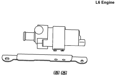
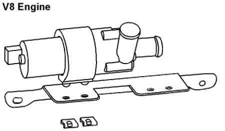
28. Attach the new auxiliary heater pump to the new bracket using the supplied retainers as shown. Note the position of the pump on the bracket.
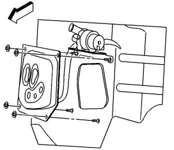
29. Install the auxiliary heater pump and bracket onto the dash panel studs.
30. Reinstall the HVAC plate and nuts.
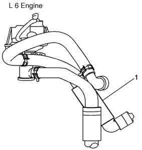
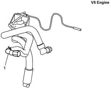
31. On the coolant bypass valve, remove the hose (1) that went from the valve to the engine and discard.
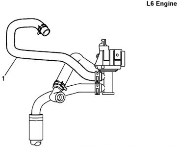
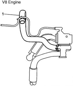
32. Install the new hose (1), # 1005 (L6 engine) or# 1006 (V8 engine) onto the coolant bypass valve at the location the above hose was removed. The other end of this hose will be installed on the auxiliary heater pump outlet port.
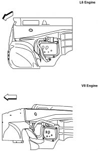
33. Install the new hose, # 1003 (L6 engine) or # 1004 (V8 engine) onto the auxiliary heater pump inlet port. Connect the other quick connect end to the engine.
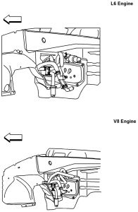
34. Install the coolant bypass valve to its original location and secure with a nut.
35. Connect the other end of the new hose from step 29 to the outlet port of the auxiliary heater pump.
36. Connect the vacuum hose to the coolant bypass valve.
37. Connect the coolant bypass valve hose to the auxiliary rear heater line.
38. Install the heater hose quick connect retainers to the heater core pipes.
39. Connect the remaining two hoses to the heater core.
40. Install the new auxiliary heater pump wiring harness to the vehicle.
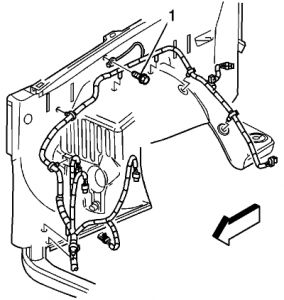
40.1. Install the ring terminal (black wire) to ground G103 (1), located on the right side inner tender.
40.2. Route the pump wiring harness along the existing right side forward lamp harness.
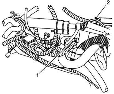
40.3. Connect the electrical connectors to the coolant bypass valve (1) and auxiliary heater pump (2).
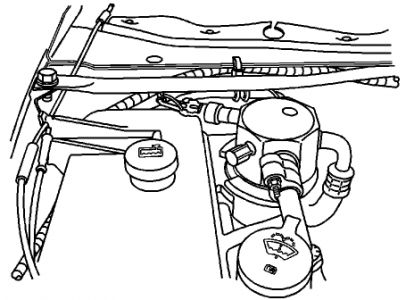
40.4. Position the relays onto the inner wheelhouse panel near the rear of the engine compartment.
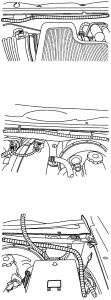
40.5. Route the other end of the harness along the rear of the engine compartment to the left side and secure to the cross bar and dash panel with tie straps.
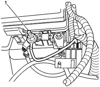
40.6. Install the ring terminal (orange wire) to the underhood fuse block stud (1).
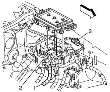
40.7. Locate circuit no. 241 or 441 (ignition 3 brown wire) (PIN B11 or C11) in the existing under-hood fuse block harness (1) of C2 (2) and splice bare wire to it using a splice clip. Wrap with electrical tape.
40.8. Locate connector C105 (3), located on the left side inner fender. Separate the connector halves. On the female side of the connector, remove the terminal from cavity F (gray/black wire) and tape back.
40.9. Install the terminal end on the pump wiring harness into cavity F of connector C105.
41. Install the evaporator tube and nut to the evaporator.
Tighten
Tighten the nut to 28 N.m (21 lb ft).
42. Install the coolant recovery reservoir with the accumulator attached.
43. Install the nut and bolt securing the coolant recovery reservoir.
44. Install the coolant hoses to the coolant recovery reservoir.
45. Install the nut retaining the accumulator to the evaporator.
Tighten
Tighten the nut to 28 N.m (21 lb ft).
46. Install the compressor suction hose assembly to the accumulator.
Tighten
Tighten the nut to 48 N.m (35 lb ft).
47. Connect the electrical connector to the A/C low pressure switch.
48. Install the lower air cleaner housing/washer solvent tank assembly onto the mounting studs.
49. Install the two air cleaner housing/washer tank assembly retaining nuts to the mounting studs.
50. Connect the washer pump hoses.
51. Connect the washer solvent tank electrical and install wiring harness to the retaining clips.
52. Install the air inlet duct to the lower air cleaner housing/washer solvent tank assembly.
53. Install the air cleaner filter element and air outlet duct.
54. Install the air cleaner cover.
55. Install the tender rear upper brace.
56. Connect the negative battery cable.
57. Recharge the refrigerant system.
58. Fill the cooling system.
59. Inspect the cooling system for leaks.
60. Leak test the refrigerant fittings using J 39400-A.
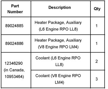
Parts Information
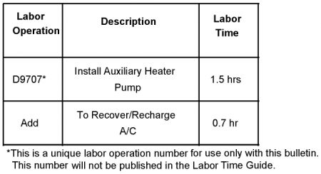
Warranty Information
Nonetheless, it is better to "Know Your Enemy BEFORE Entering Battle..." and by following THIS Documentation and the Repair Steps, it will end up bringing a smile to the Passengers in the 2003-2005 Trailblazers and Envoys with Heat Distribution Issues in Winter Time:
Source and Credit:
2005 Chevy Trailblazer Rear Heater: Hi, the Rear Heater Vents Just...
Hi, the rear heater vents just blow cold air. The vents for the front system blow hot air and the engine temp is to specs. You can control the rear ...
A/C - Poor Rear Heater Performance
Notes
Bulletin No.: 05-01-37-002A
Date: November 01, 2005
TECHNICAL
Subject:
Poor Rear Heat Performance (Install Auxiliary Heater Pump)
Models:
2003-2005 Chevrolet TrailBlazer EXT
2003-2005 GMC Envoy XL
Supercedes:
This bulletin is being revised to update the correction information. Please discard Corporate Bulletin Number 05-01-37-002 (Section 01 - HVAC).
Important: Implementation of this Service Bulletin by "GM of Canada" dealers requires prior District Service Manager approval.
Condition
Some customers may comment on poor 2nd and/or 3rd row seating heater performance when the vehicle is at idle.
Cause
This condition may be due to lack of coolant circulation to the rear heater core.
Correction
Install auxiliary heater pump package, P/N 89024885 (L6 Engine RPO LL8) or P/N 89024886 (V8 Engine RPO LM4 or LH6). This pump will improve coolant flow to the rear heater core. Use the procedure listed below.
1. Recover the A/C refrigerant.
2. Drain the cooling system.
3. Disconnect the negative battery cable.
4. Remove the fender rear upper brace.
5. Remove the air cleaner cover.
6. Remove the air cleaner filter element and air outlet duct.
7. Remove the air inlet duct from the lower air cleaner housing/washer solvent tank assembly.
8. Disconnect the washer solvent tank electrical and remove wiring harness from the retaining clips.
9. Disconnect the washer pump hoses and plug the pump outlet ports to prevent loss of washer solvent.
10. Remove the two air cleaner housing/washer tank assembly retaining nuts from the mounting studs.
11. Lift the lower air cleaner housing/washer tank assembly off of the studs and remove the assembly.
12. On the A/C accumulator, disconnect the electrical connector from the low pressure switch.
13. Remove the compressor suction hose assembly from the accumulator.
14. Remove the nut retaining the accumulator to the evaporator.
15. Remove the coolant hoses from the coolant recovery reservoir.
16. Remove the nut and bolt securing the coolant recovery reservoir.
17. Remove the coolant recovery reservoir with the accumulator attached.
18. Remove the evaporator tube nut at the evaporator.
19. Remove the evaporator tube from the evaporator
20. Using the J 43181, disconnect the heater hoses from the core.
20.1. Install the J 43181 to the heater core hose.
20.2. Close the tool around the heater core hose.
20.3. Firmly pull the tool into the quick connect end of the heater hose.
20.4. Firmly grasp the heater hose. Pull the heater hose forward in order to disengage the hose from the heater core.
21. Disconnect the coolant bypass valve hose from the auxiliary rear heater line.
22. Disconnect the coolant bypass valve hose from the engine.
23. Disconnect the electrical connector from the coolant bypass valve. This connector will no longer be used. Tape off with electrical tape.
24. Disconnect the vacuum hose from the coolant bypass valve.
25. Remove the nut retaining the coolant bypass valve to the cowl and remove the coolant bypass valve with hoses attached.
26. Remove the heater hose quick connect retainers from the heater core pipes.
27. Remove the four nuts and the HVAC plate from the dash panel.


28. Attach the new auxiliary heater pump to the new bracket using the supplied retainers as shown. Note the position of the pump on the bracket.

29. Install the auxiliary heater pump and bracket onto the dash panel studs.
30. Reinstall the HVAC plate and nuts.


31. On the coolant bypass valve, remove the hose (1) that went from the valve to the engine and discard.


32. Install the new hose (1), # 1005 (L6 engine) or# 1006 (V8 engine) onto the coolant bypass valve at the location the above hose was removed. The other end of this hose will be installed on the auxiliary heater pump outlet port.

33. Install the new hose, # 1003 (L6 engine) or # 1004 (V8 engine) onto the auxiliary heater pump inlet port. Connect the other quick connect end to the engine.

34. Install the coolant bypass valve to its original location and secure with a nut.
35. Connect the other end of the new hose from step 29 to the outlet port of the auxiliary heater pump.
36. Connect the vacuum hose to the coolant bypass valve.
37. Connect the coolant bypass valve hose to the auxiliary rear heater line.
38. Install the heater hose quick connect retainers to the heater core pipes.
39. Connect the remaining two hoses to the heater core.
40. Install the new auxiliary heater pump wiring harness to the vehicle.

40.1. Install the ring terminal (black wire) to ground G103 (1), located on the right side inner tender.
40.2. Route the pump wiring harness along the existing right side forward lamp harness.

40.3. Connect the electrical connectors to the coolant bypass valve (1) and auxiliary heater pump (2).

40.4. Position the relays onto the inner wheelhouse panel near the rear of the engine compartment.

40.5. Route the other end of the harness along the rear of the engine compartment to the left side and secure to the cross bar and dash panel with tie straps.

40.6. Install the ring terminal (orange wire) to the underhood fuse block stud (1).

40.7. Locate circuit no. 241 or 441 (ignition 3 brown wire) (PIN B11 or C11) in the existing under-hood fuse block harness (1) of C2 (2) and splice bare wire to it using a splice clip. Wrap with electrical tape.
40.8. Locate connector C105 (3), located on the left side inner fender. Separate the connector halves. On the female side of the connector, remove the terminal from cavity F (gray/black wire) and tape back.
40.9. Install the terminal end on the pump wiring harness into cavity F of connector C105.
41. Install the evaporator tube and nut to the evaporator.
Tighten
Tighten the nut to 28 N.m (21 lb ft).
42. Install the coolant recovery reservoir with the accumulator attached.
43. Install the nut and bolt securing the coolant recovery reservoir.
44. Install the coolant hoses to the coolant recovery reservoir.
45. Install the nut retaining the accumulator to the evaporator.
Tighten
Tighten the nut to 28 N.m (21 lb ft).
46. Install the compressor suction hose assembly to the accumulator.
Tighten
Tighten the nut to 48 N.m (35 lb ft).
47. Connect the electrical connector to the A/C low pressure switch.
48. Install the lower air cleaner housing/washer solvent tank assembly onto the mounting studs.
49. Install the two air cleaner housing/washer tank assembly retaining nuts to the mounting studs.
50. Connect the washer pump hoses.
51. Connect the washer solvent tank electrical and install wiring harness to the retaining clips.
52. Install the air inlet duct to the lower air cleaner housing/washer solvent tank assembly.
53. Install the air cleaner filter element and air outlet duct.
54. Install the air cleaner cover.
55. Install the tender rear upper brace.
56. Connect the negative battery cable.
57. Recharge the refrigerant system.
58. Fill the cooling system.
59. Inspect the cooling system for leaks.
60. Leak test the refrigerant fittings using J 39400-A.

Parts Information
Warranty Information

Last edited:
