You are using an out of date browser. It may not display this or other websites correctly.
You should upgrade or use an alternative browser.
You should upgrade or use an alternative browser.
NEED HELP U1000 code, Class 2 Serial Communication Problem
- Thread starter Harut
- Start date
Welcome to GMT Nation. U1000 is a "Class 2 Data Link Malfunction"; suggests one or more modules is not talking/listening properly. The symptoms you describe are similar to those in this thread: Liftgate electrical problems.
The problem(s) could be with the Liftgate module, connectors, grounds, etc. Read thru the whole thread as it has a number of detailed responses on the OP's progress as well as additional useful links.
The problem(s) could be with the Liftgate module, connectors, grounds, etc. Read thru the whole thread as it has a number of detailed responses on the OP's progress as well as additional useful links.

Mooseman
Moderator
Anything else not working properly? Sometimes a module goes bad and kills all communication on the network. However, if it's just stuff in the liftgate that's not working, including the key fob, check the wiring in the liftgate wiring boot. Wires tend to break in there.
 gmtnation.com
SOLVED! - Replaced liftgate - now electrical problems
Hello, I have a 2003 TB LTZ. The liftgate was rotting in the usual spots, only had 4 lines for the defroster work, and would not lock/unlock. I found a nice liftgate from a 2006 TB LT. While I was disconnecting the electrical connector, I could hear the lock for the liftgate making noise as I...
Mooseman
Moderator
Mooseman
Moderator
Just peel the boot back and pull on each one. Some may be evidently broken but some may have broken copper inside the insulation.


Mooseman
Moderator
They're on a separate circuit, the brown wire. The LGM could be dead or have a broken wire and they would still work.And the rear plates lights also working.
Mooseman
Moderator
Mooseman
Moderator
Mooseman
Moderator
As per the RFA from @Mooseman for the OP ...
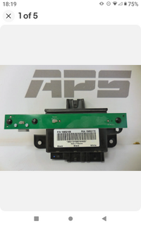
Regarding images of the LGM Wiring and Connectors, be advised that although there are (3) Distinct Connectors along with (3) Distinct Rear Lift Gate Functions ...
(1) Rear Windshield Wiper
(2) The Rear Glass Window Latch
(3) The Rear Lift Gate Locking Latch Mechanism
(4) In some cases for Key-Less Entry...
...You will find that SOME of EACH of those Wires coming from each of the Three Connectors SHARE Functionality through the BCM interface in between ALL (1-3) of these Unique Functions,
Thus, referring to the Class 2 Network Color Coded Wiring Diagram shown below will help in figuring out how to "unravel" how ALL THREE Connectors are cross-intertwined and well describes their subtle coloring of each wire:

Photobucket Link to the GMT360 SUV Lift Gate Module Wiring and Connector Imagery:
 app.photobucket.com
Regarding images of the LGM Wiring and Connectors, be advised that although there are (3) Distinct Connectors along with (3) Distinct Rear Lift Gate Functions ...
(1) Rear Windshield Wiper
(2) The Rear Glass Window Latch
(3) The Rear Lift Gate Locking Latch Mechanism
(4) In some cases for Key-Less Entry...
...You will find that SOME of EACH of those Wires coming from each of the Three Connectors SHARE Functionality through the BCM interface in between ALL (1-3) of these Unique Functions,
Thus, referring to the Class 2 Network Color Coded Wiring Diagram shown below will help in figuring out how to "unravel" how ALL THREE Connectors are cross-intertwined and well describes their subtle coloring of each wire:
Photobucket Link to the GMT360 SUV Lift Gate Module Wiring and Connector Imagery:
Photo Storage
Store your photos and videos online with secure storage from Photobucket. Available on iOS, Android and desktop. Securely backup your memories and sign up today!
I checked the wires that come inside the LCM are ok. But there are no power in
Rear Windshield Wiper and in the Rear Glass Window Latch. So what does it's mean? It's mean that LCM need change? And if we changed it, it will need to be programmed or no??????
Rear Windshield Wiper and in the Rear Glass Window Latch. So what does it's mean? It's mean that LCM need change? And if we changed it, it will need to be programmed or no??????
While you are investigating the Electrical Issues... bear in mind that the Lift Gate Glass Rear Window can also suffer from Mechanical Failures within its sub-hinges. This is an excellent "How To" for dealing with this problem:
The same can be said for the Lift Gate Latch... and so from the same clever, intrepid VOP (Video Original Poster) is yet another "How To" for dealing with THIS Problem:
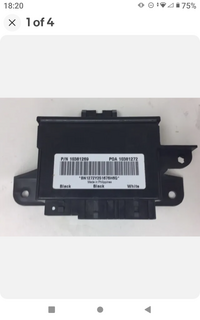
As for having a possibly FUBAR'd LGM, pull the actual GM - ACDelco Part Number off of the one in-dwelling and then search over on eBay for a few Used Ones. I picked up mine (Thankfully, a Failed Unit as described-documented in the LGM Links and Images above) for around $15.00 per item quite a few years back while trying to Dope out a Bench Top Harness. As long as the P/Ns match... the Used One should work without the need for a Tech 2 Scan Tool to re-program the Module onto the Class 2 Network. Check yours against THESE available over on eBay:

As a solution once suggested to us by @TJBaker57... You would also be well advised to raise the Passenger Seat on the Driver's Side of the SUV and after removing the BCM Plastic Cover, examine the Gold-Green Flex Harness interface for an invasion of Spilled Soda and Odd Debris... and then Spray it out well using CRC Electrical Contact Solvent available from Amazon and AutoZone for not too much bread.
You can familiarize yourself with the appearance of the GMT360's Green BCM Cable & Harness Connectors via THIS Link:
app.photobucket.com
By The Way... Will Robinson's Classic Lost Network Communications Diagnostics Video is worth going over, too. Download, Save and STUDY what he does here to Isolate and Identify ANY Class 2 Network Module that can Fail and Bring Down The Entire Network on GMT360 Vehicles:
The same can be said for the Lift Gate Latch... and so from the same clever, intrepid VOP (Video Original Poster) is yet another "How To" for dealing with THIS Problem:
As for having a possibly FUBAR'd LGM, pull the actual GM - ACDelco Part Number off of the one in-dwelling and then search over on eBay for a few Used Ones. I picked up mine (Thankfully, a Failed Unit as described-documented in the LGM Links and Images above) for around $15.00 per item quite a few years back while trying to Dope out a Bench Top Harness. As long as the P/Ns match... the Used One should work without the need for a Tech 2 Scan Tool to re-program the Module onto the Class 2 Network. Check yours against THESE available over on eBay:
trailblazer lift gate module for sale | eBay
Get the best deals for trailblazer lift gate module at eBay.com. We have a great online selection at the lowest prices with Fast & Free shipping on many items!
www.ebay.com
As a solution once suggested to us by @TJBaker57... You would also be well advised to raise the Passenger Seat on the Driver's Side of the SUV and after removing the BCM Plastic Cover, examine the Gold-Green Flex Harness interface for an invasion of Spilled Soda and Odd Debris... and then Spray it out well using CRC Electrical Contact Solvent available from Amazon and AutoZone for not too much bread.
You can familiarize yourself with the appearance of the GMT360's Green BCM Cable & Harness Connectors via THIS Link:
Photo Storage
Store your photos and videos online with secure storage from Photobucket. Available on iOS, Android and desktop. Securely backup your memories and sign up today!
By The Way... Will Robinson's Classic Lost Network Communications Diagnostics Video is worth going over, too. Download, Save and STUDY what he does here to Isolate and Identify ANY Class 2 Network Module that can Fail and Bring Down The Entire Network on GMT360 Vehicles:
Last edited:
First, View THIS Video from @MAY03LT on locating the Class 2 Network Ground Splice Pack situated on the Passenger Side Transmission Hump under the Dash Panel Console Cover to R&R it and Clean the Contact Surface for the 10mm Bolt securing it to the Metal Body of the SUV...
...and watch THIS Video as a 'Hands On Class 2 Network Diagnostic Approach' to View How the Network 0-7 Volts Communication Square Waves should appear on any Auto Oscilloscope:
Then... Check Out this ENTIRE Thread... But FOCUS in particular in Post #18:
gmtnation.com
And ... Use the Class 2 Network Wiring Diagram shown above in Post #16 above in conjunction with @Realism 's Epic "Ground Location" images in THIS Thread to isolate the LGM Network Ground Circuit Splice Pack interface:
gmtnation.com
Also... Remember that what follows is just to Demonstrate "The Principles of The General Motors Class 2 Network Diagnostic Procedures"
The OP at iATN tried using his MODIS Ultra High End Scan Tool on a 2006 Chevrolet Silverado in conjunction with his Tech 2 OEM Scan Tool... WITH A TOTAL LOSS OF CLASS 2 NETWORK COMMUNICATION TO BOTH SCAN TOOLS.
It followed on that he very enthusiastically performed these Proper "Step By Steps" while investigating a "Class 2 Network Short To Positive (B+) Voltage" Problem and solved the issue after discovering that Mice or Rats had Chewed through the Wiring and Shorted out the system to Power at the Underhood Lower Fuse Box of the vehicle.
Copy-Paste THIS Information in your Word Processor, strictly to get a 'Look & Feel' of the helpful ways to do this Diagnostic in an Organized and Thoughtful Fashion:
Excerpt of text and GMT800 Images are Available From IATN ...HERE:

 www.iatn.net
2006 Silverado Class 2 Data Bus Shorted
Posted to Technical Tips Forum on 3/2/2015 23 Replies
"This system, and possibly the issues, are likely old news to many of you, but it was my first time getting a broken data bus on a GM. After many classes and forum posts, I was quite excited to dig into it.
The customer complaint was that the dash was inoperative and there were numerous warning lights illuminated. A code scan on a Snap On Modis Ultra and the Tech 2 network test would not communicate with any module.
A DLC schematic 2006 Chevrolet Silverado 1500 LS, ECM/Inputs/Outputs Schematic shows me that it's a simple, low speed Class 2 data bus.
I plugged in a DLC break out box and scoped pin 2 with KOEO. 2006 Chevrolet Silverado 1500 LS, ECM/Inputs/Outputs Waveform I know that I should be seeing 7 volts and at least some activity, but this was flat lined at nearly 5 volts.
Luckily GM was nice enough to install a splice pack to make our lives easier on these 2006 Chevrolet Silverado 1500 LS, ECM/Inputs/Outputs Photo Removing the shorting bar I can easily check each circuit. 2006 Chevrolet Silverado 1500 LS, ECM/Inputs/Outputs Photo
I cross referenced the wire colors of SP205 with a schematic, and jumped pin D, which goes to the DLC, to the other wires. 2006 Chevrolet Silverado 1500 LS, ECM/Inputs/Outputs Schematic
I got some activity when jumping pin D to pin M (BCM) 2006 Chevrolet Silverado 1500 LS, ECM/Inputs/Outputs Waveform The other pins stayed at 0V, except for pin K.
Pin K jumped up to a steady 11V 2006 Chevrolet Silverado 1500 LS, ECM/Inputs/Outputs Waveform indicating to me that this baby is shorted to power.
Looking back at the diagram, on the top right, it shows three possible modules with three wires terminating at pin K of SP205. Luckily I only had one Orange/ Black wire at Pin K. This lead me to the Generator Battery Control Module. 2006 Chevrolet Silverado 1500 LS, BATT/Charging/Starting Photo Unplugging the module did not change the voltage at the DLC. The Orange/ Black wire at module also showed the same 11V.
Time to find C100 located between the module and DLC 2006 Chevrolet Silverado 1500 LS, ECM/Inputs/Outputs Photo Conveniently, it's right next to where I already am, underneath the Underhood Fuse box 2006 Chevrolet Silverado 1500 LS, ECM/Inputs/Outputs Photo
With the large fuse box covers removed, you can easily flip the fuse box up and peek underneath. 2006 Chevrolet Silverado 1500 LS, ECM/Inputs/Outputs Photo The first photo is a little hard to tell, but there was some very shiny copper smiling at me under there. Here's a closer look with the connector unplugged. 2006 Chevrolet Silverado 1500 LS, ECM/Inputs/Outputs Photo 2006 Chevrolet Silverado 1500 LS, ECM/Inputs/Outputs Photo
The Orange/ Black wire has the insulation chewed off and is shorting out next to the Green/ White wire next to it.
Wham, Bam, thank you rodents. I repaired the wiring and all of my modules were happy and talking. 2006 Chevrolet Silverado 1500 LS, ECM/Inputs/Outputs Waveform Coincidentally, I had a Suburban in a few months back with a whole bunch of wires chewed up in the same area. I guess the rodents like that fuse box.
I had so much fun doing this that I just had to document my process to share with my iATN people. Hopefully this might help someone down the line someday."
Last But Not Least... In a very similar Visual Example... the VOP (Video Original Poster) Discovers in a GMC Denali 1500 that when the Engine Ground is NOT connected to the Back of the Engine Block at the Firewall during a recent Motor Swap... The 5 Volt Reference Signal for the Class 2 Network examined-tested at the MAP Sensor showed that the Signal Power will SHORT TO A HIGHER VOLTAGE of near 10 to 11 Volts DC. Again, the importance here is to Use THIS Example as well to Learn The Proper Procedures for Universal Class 2 Network Problem Diagnostics:
...and watch THIS Video as a 'Hands On Class 2 Network Diagnostic Approach' to View How the Network 0-7 Volts Communication Square Waves should appear on any Auto Oscilloscope:
Then... Check Out this ENTIRE Thread... But FOCUS in particular in Post #18:
SOLVED! - No Start, Multiple U1000 codes, Class 2 Serial Communication Problem
2005 Chevy Trailblazer LT, 2-Door, 4WD, I6 4.2L engine Won't start or turn over. No starter signal at starter relay but when jump relay will turn over but not start. No check engine light. All instrument light on when first to key on the go out except battery & gauge warning light stay on...
And ... Use the Class 2 Network Wiring Diagram shown above in Post #16 above in conjunction with @Realism 's Epic "Ground Location" images in THIS Thread to isolate the LGM Network Ground Circuit Splice Pack interface:
Electrical Ground locations
While troubleshooting a bad ground I came across some scans of the service manual regarding electrical ground locations for our platform posted on another site. This includes both short and long wheel base, as well as both 4.2L and 5.3L. Credit goes to Wex...
Also... Remember that what follows is just to Demonstrate "The Principles of The General Motors Class 2 Network Diagnostic Procedures"
The OP at iATN tried using his MODIS Ultra High End Scan Tool on a 2006 Chevrolet Silverado in conjunction with his Tech 2 OEM Scan Tool... WITH A TOTAL LOSS OF CLASS 2 NETWORK COMMUNICATION TO BOTH SCAN TOOLS.
It followed on that he very enthusiastically performed these Proper "Step By Steps" while investigating a "Class 2 Network Short To Positive (B+) Voltage" Problem and solved the issue after discovering that Mice or Rats had Chewed through the Wiring and Shorted out the system to Power at the Underhood Lower Fuse Box of the vehicle.
Copy-Paste THIS Information in your Word Processor, strictly to get a 'Look & Feel' of the helpful ways to do this Diagnostic in an Organized and Thoughtful Fashion:
Excerpt of text and GMT800 Images are Available From IATN ...HERE:
Class 2 data bus shorted
This system, and possibly the issues, are likely old news to many of you, but it was my first time getting a broken data bus on a GM. After many classes and forum posts, I was quite excited to dig into it. The customer complaint was that the dash was inoperati
2006 Silverado Class 2 Data Bus Shorted
Posted to Technical Tips Forum on 3/2/2015 23 Replies
"This system, and possibly the issues, are likely old news to many of you, but it was my first time getting a broken data bus on a GM. After many classes and forum posts, I was quite excited to dig into it.
The customer complaint was that the dash was inoperative and there were numerous warning lights illuminated. A code scan on a Snap On Modis Ultra and the Tech 2 network test would not communicate with any module.
A DLC schematic 2006 Chevrolet Silverado 1500 LS, ECM/Inputs/Outputs Schematic shows me that it's a simple, low speed Class 2 data bus.
I plugged in a DLC break out box and scoped pin 2 with KOEO. 2006 Chevrolet Silverado 1500 LS, ECM/Inputs/Outputs Waveform I know that I should be seeing 7 volts and at least some activity, but this was flat lined at nearly 5 volts.
Luckily GM was nice enough to install a splice pack to make our lives easier on these 2006 Chevrolet Silverado 1500 LS, ECM/Inputs/Outputs Photo Removing the shorting bar I can easily check each circuit. 2006 Chevrolet Silverado 1500 LS, ECM/Inputs/Outputs Photo
I cross referenced the wire colors of SP205 with a schematic, and jumped pin D, which goes to the DLC, to the other wires. 2006 Chevrolet Silverado 1500 LS, ECM/Inputs/Outputs Schematic
I got some activity when jumping pin D to pin M (BCM) 2006 Chevrolet Silverado 1500 LS, ECM/Inputs/Outputs Waveform The other pins stayed at 0V, except for pin K.
Pin K jumped up to a steady 11V 2006 Chevrolet Silverado 1500 LS, ECM/Inputs/Outputs Waveform indicating to me that this baby is shorted to power.
Looking back at the diagram, on the top right, it shows three possible modules with three wires terminating at pin K of SP205. Luckily I only had one Orange/ Black wire at Pin K. This lead me to the Generator Battery Control Module. 2006 Chevrolet Silverado 1500 LS, BATT/Charging/Starting Photo Unplugging the module did not change the voltage at the DLC. The Orange/ Black wire at module also showed the same 11V.
Time to find C100 located between the module and DLC 2006 Chevrolet Silverado 1500 LS, ECM/Inputs/Outputs Photo Conveniently, it's right next to where I already am, underneath the Underhood Fuse box 2006 Chevrolet Silverado 1500 LS, ECM/Inputs/Outputs Photo
With the large fuse box covers removed, you can easily flip the fuse box up and peek underneath. 2006 Chevrolet Silverado 1500 LS, ECM/Inputs/Outputs Photo The first photo is a little hard to tell, but there was some very shiny copper smiling at me under there. Here's a closer look with the connector unplugged. 2006 Chevrolet Silverado 1500 LS, ECM/Inputs/Outputs Photo 2006 Chevrolet Silverado 1500 LS, ECM/Inputs/Outputs Photo
The Orange/ Black wire has the insulation chewed off and is shorting out next to the Green/ White wire next to it.
Wham, Bam, thank you rodents. I repaired the wiring and all of my modules were happy and talking. 2006 Chevrolet Silverado 1500 LS, ECM/Inputs/Outputs Waveform Coincidentally, I had a Suburban in a few months back with a whole bunch of wires chewed up in the same area. I guess the rodents like that fuse box.
I had so much fun doing this that I just had to document my process to share with my iATN people. Hopefully this might help someone down the line someday."
Last But Not Least... In a very similar Visual Example... the VOP (Video Original Poster) Discovers in a GMC Denali 1500 that when the Engine Ground is NOT connected to the Back of the Engine Block at the Firewall during a recent Motor Swap... The 5 Volt Reference Signal for the Class 2 Network examined-tested at the MAP Sensor showed that the Signal Power will SHORT TO A HIGHER VOLTAGE of near 10 to 11 Volts DC. Again, the importance here is to Use THIS Example as well to Learn The Proper Procedures for Universal Class 2 Network Problem Diagnostics:
Last edited:
Mooseman
Moderator