Tech 2 Repair

DeltaAngler

Member
Joined
Jul 15, 2023
Posts
7
Location
Texas
Hello,
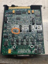
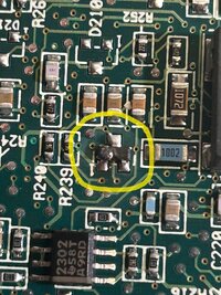
I have a GM Tech 2 made by Vetronics and I need a new logic board for it. Does anyone know if they are available at all and if so, where I can get one? One of the pins in memory card slot was damaged. I attempted to fix it, but apparently it is still not making a good connection. I get power on, but it doesn't do anything other than show "system initializing" and none of the other keys work.
 
Is it a genuine (gag.. cough...) or one of the usual clones?

I'll lay you odds that any parts that are available would be genuine, and cost 1000 times what a whole new clone unit would be.

I managed to find JUST the unit many years ago - no cables, no case, nothing. Sometimes if you email a seller directly they'll arrange something like that.
 
Try following this Dude (His Chenglish is AWFUL ...but the Video is Good) in performing the "GYMKO" Tech 2 Self Test Procedures after removing the VCI Module and Spraying it out with CRC Electronic Component Solvent. Sometimes... just by *Cleaning & Exercising* the VCI Slide Lock Mechanism and DLC Cable installation ... you can awaken the Tech 2 from out of its Slumber.

Don't ignore the possibility of having Cracked or Poorly Soldered Lead on SMCs (Surface Mounted Components) present on the PCB after carefully disassembling the system and then using a powerful, inexpensive USB Microscope to find the errant component or corroded-dirty interface:


Also follow up with watching all of the Tech 2 Videos presented by "Dr. Shock" at his YouTube Channel for many Step By Steps with tearing these Tech 2s apart and re-assembling them in working order:


Check out Amazon for the CRC Circuit Board Solvent:


618DEAhKusL._AC_SL1500_.jpg

For Related On Topic Threads:


Last edited:
You do know that there is a second slot? It's just above the other one.
 
Thank you all for your replies to my post. I have tried your suggestions and visited recommended videos. After trying may things and cleaning up some residue flux on several parts of the board and other connections, I finally got my Tech 2 working. How ever on the "Power On Test Results", I got a Fail on URAT. What is this and what can I do to fix it? I also ran the "Automated Main PCB and VCI" test and all passed. Please help!
 
  • Love
Reactions: mrrsm
Mine fails on one of those tests but it still works. It could be for something inconsequential. If it still works, I'd ignore it.

One day I'll have to make a video of mine on boot up so I can read which one it is since it goes by so fast.
 
  • Like
Reactions: mrrsm
Unless you are using your Tech 2 Scan Tool in a Bench Top Diagnostics and Calibration or Programming Activity... It is critical to remember to ONLY Power The Tech 2 through the Power Connection situated on the DLC Connector fitted Under The Dashboard and NOT using the one located on the Lower Right Corner of the Tech 2 Unit.
 
I was running the Tech 2 with the AC Adapter and tried with both the bench top plug and the full cord used for the vehicle. Got the same results with both, no matter where I plug in the AC Adapter. All but one test result passed, one failed for URAT. According to my user guide when hooked up in the vehicle the cigerete lighter adapter needs to be hook up to the Adapter that plugs into the car port to insure proper grounding. I will try to research to and find out what URAT is and how to fix it, however if any one of you know please reply. Thaks for the help so far.....
 
  • Like
Reactions: mrrsm
NP... The placement of the DC Power Input Issue has more to do with lending Power directly into the DLC Port rather than through the Tech 2, since the Power Fluctuations tolerated by the OEM DC-to-DC Converter mounted arbitrarily on the PCB is Fault Tolerant in between 8 Volts DC and 18 Volts DC.

It is BEST to *** Avoid Using the Cigarette Lighter for a Power Source *** and connect the Power and Grounds directly from the Truck-SUV Battery instead. Avoid using the A/C to DC Power Converter to avoid "Bricking" the Calibration Read-Writes due to the possibility of having External A/C Radio Frequency Interference fluctuations getting inducted into the Communications Circuit.

However, the Off-The-Shelf Replacement DC-to-DC Converter replacements are NOT so forgiving and thus... directly inducing the DC Voltage into the DLC Port Pin 16 for B+ Voltage and using Pins 4 & 5 for the Body AND the PCM Ground are CRITICAL for providing the very stable Voltage needed during ANY Calibration Writes to the In-Dwelling PCM. Naturally... having a Fully Charged 12 Volt Vehicle Battery supported by a Battery Maintainer are also prerequisites here as well.
 
Last edited:
URAT = UART (Universal Asynchronous Receiver Transmitter)


The reason your are getting this UART Error is because without having a Special Loop Back Plug inserted into the RS-485 - RJ-485 Female Port on the Left side of the Tech-2 adjacent the RS-232 - RJ-45 Insert Port ...it will NOT be able to run and complete that particular portion of The System Diagnostics Tests. :>)
 
Last edited:
URAT = UART (Universal Asynchronous Receiver Transmitter)


The reason your are getting this UART Error is because without having a Special Loop Back Plug inserted into the RJ-485 Female Port on the Left side of the Tech-2 adjacent the RS-232 - RJ-232 Insert Port ...it will NOT be able to run and complete that particular portion of The System Diagnostics Tests. :>)
Thanks for the Info mrrsm. Do you know what type of diagnostic tests are done using the RJ-485 loop back plug? I am just wondering if that is something I may need. Also do you know if the JR-485 loop back plug is readily available online.
 
There were only Two Chinese "GYMKO" PCBs made for the various Bosch Vetronix OEM Tech 2 Knock Offs made for the NAO and European Markets. In one of the two... the RS-485 - RJ-485 inserts were meant for the OEM Bench Top Calibration Testing done during Post Manufacture and "Custom Customer Orders" Assembly. In some cases... the Chinese did NOT even bother with soldering in that port at all.

Please note that ALL of the Peripherals (RS-232, RS-485, DC-to-DC Converter and the VCI Interfaces) were added on AFTER the manufacture of the PCB Logic Boards by Hand Soldering. Thus, their Quality and Functionality can often vary a great deal... AND YET... each component can still be easily fixed by Re-Flowing their Soldered Joints if necessary.

There were also Two Variants for the Blue Skim Coated Viewing Screens, too. One used a Multi-Pin Interface to allow for the easy detachment - re-attachment of the "Blue" Screen for access to the areas underneath it... and the other was simply Hard Soldered onto the PCB. In any case, as mentioned by @Mooseman in Post #6 ...

"If it WORKS... Don't FIX It!" :>)
 
Last edited:
  • Like
Reactions: Mooseman
I don't know if this has already been covered. I bought a GM TECH-2, and didn't work right. Never been taken apart, and looks like never used. Kept showing RS232 loop-back not present. Checked the MAX232, and it seemed fine. So looked over the main board, and on the back, a Lithium battery! It was dead! Replaced and all the problems have disappeared! Will know if it is working right soon.
 
Welcome to GMT Nation...

Well Done on your Tech 2 R&R Diagnostic and Discovery of the Failed "Coin" Battery... Others of us who own Disabled Tech 2 Scanners will benefit from knowing what you have just figured out... and that making the Battery Replacement "...is worth a try" to Repair their Scan Tools.

The "RS-232 Loop-Back Tester NOT PRESENT" simply means that THIS Item was NOT plugged into the RJ-45 Port situated on the Left Side of the Tech 2 Scan Tool with the Blue Screen facing UP:

If you have any of the 4 Pair Twisted CAT-5 or CAT-6 Cable (8 Wire) Terminals and a Length of Spare Cable along with an inexpensive RJ-45 Connector Repair Kit... you can make your own version using this Wiring Pattern... literally "Looping Back" the signal transmissions used by the "GYMKO" Tech 2 during Boot-Up and the Self-Diagnostic:

An 8 Pin RJ-45 Loop-Back Clear Plastic Test Plug should be wired as follows:

Pin 2 connected to pin 7 (RTS to CTS)
Pin 4 connected to pin 5 (TxD to RxD)
Pin 1 connected to pin 8 (DTR to DSR)

rj45++color+code-min-812643445.jpg

RJ45-plug-loopback-1547762183.jpgHTB11D8cIVXXXXXsXFXXq6xXFXXXR-1129815048.jpghow-to-make-a-loopback-plug-1439852650.jpg

Or... You can always purchase one on eBay for a mere $5.20:

s-l1600.jpg

 
Last edited:
  • Like
Reactions: Mooseman
After tracing the wiring for the RJ-45 on main board, only need 2 jumpers, 1 to 8 and 4 to 5. The other pins are 2 no connection, 3 tied to 6, but no connection to any circuit, 7 is connected to main board ground. Also had to set the internal clock to 2006 or got another fail. Tried it on H2, and found no fault codes, so I guess it works?
 
  • Like
Reactions: mrrsm
I never thought about the internal clock. I guess beyond a certain year (2013?) it doesn't work, sorta like Y2K back with some older computers. I guess 2006 works as the same as 2023. Maybe have to do the same with the laptop running Tis2000.
 
  • Like
Reactions: mrrsm
VETRONIX GM TECH 2 DIAGNOSTIC SCANNER Victron does not answer emails on the back of my Tech 2 it has a phone number They say they do not repair them anymore Does anybody know who to contact to get it repaired It's failing its self diagnostic I believe it's in the vci module but I can't find a parts schematic or pictures that are good enough to read what's on the burned out part so that I can replace it
 

Attachments

  • 3.jpg
    3.jpg
    86 KB · Views: 6
  • 4.jpg
    4.jpg
    615.6 KB · Views: 6
  • 5.1.jpg
    5.1.jpg
    676.6 KB · Views: 7
  • 6.jpg
    6.jpg
    506.1 KB · Views: 8
VETRONIX GM TECH 2 DIAGNOSTIC SCANNER Victron does not answer emails on the back of my Tech 2 it has a phone number They say they do not repair them anymore Does anybody know who to contact to get it repaired It's failing its self diagnostic I believe it's in the vci module but I can't find a parts schematic or pictures that are good enough to read what's on the burned out part so that I can replace it

Get some GOOD contact cleaner (there's nothing better than DeOxit) and try that on every plated contact you can find (including the Candi module cables etc!). Don't wipe it off after applying as it's a protectant as well. Scrubbing with a q-tip helps.

After that, the most common failure on these is the DC-DC converter inside the main unit. I had nothing but random issues with mine. Finally got around to replacing that, and it fixed everything. Clean, correct power... go figure! :D
 
  • Like
Reactions: Mooseman
Victron does not answer emails on the back of my Tech 2 it has a phone number They say they do not repair them anymore
This is basically 90's tech so it was bound to happen. That or they were tired answering questions about cheap clones. We're on our own I'm afraid :frown:
 
Get some GOOD contact cleaner (there's nothing better than DeOxit) and try that on every plated contact you can find (including the Candi module cables etc!). Don't wipe it off after applying as it's a protectant as well. Scrubbing with a q-tip helps.

After that, the most common failure on these is the DC-DC converter inside the main unit. I had nothing but random issues with mine. Finally got around to replacing that, and it fixed everything. Clean, correct power... go figure! :D

VETRONIX GM TECH 2 DIAGNOSTIC SCANNER Victron does not answer emails on the back of my Tech 2 it has a phone number They say they do not repair them anymore Does anybody know who to contact to get it repaired It's failing its self diagnostic I believe it's in the vci module but I can't find a parts schematic or pictures that are good enough to read what's on the burned out part so that I can replace it
When I do a self diagnostic it fails about half of tests. When I looked the VCI Here's when I found a burnt part See original pictures if I knew what the part was I'd acquire another one and put it on the board. If anyone has a board like the one pictured get a close up picture of that area for me so that I could read the value on the part
 

jozeppyman, here is the component you are wondering about. I tried researching it, but research goes in all directions as far as the alleged part number. This is from an authentic Tech2 VCI module, that I am trying to repair for a friend. The problem I'm having is not with the module, but I thought I would pull it apart and snap a picture to help you out. It is marked as 43s and to the side of the s is a vertical number 44. I hope you can cross it with something. Let me know how you make out!​


Attachments

  • 43s.jpg
    43s.jpg
    13.6 KB · Views: 4
Last edited:
This is likely a circuit protection Schottky diode based on the lead count, markings & package size. A Google search on "43s" three pin smd component "44" gives the following (AI) summary:

Based on SMD marking code databases, a three-pin SMD component with the marking "
43s" is commonly identified as a BAS40 series Schottky diode (often produced by Siemens or Infineon).


Here are the details regarding the component:
  • Part Number: BAS40 or BAS40-04 (SOT-23 package).
  • Type: Schottky Diode.
  • Package: SOT-23 (three pins).
  • Marking 43s: Refers to the BAS40 series.


Alternative Possibility:
  • Another source lists DTC143XUB (a ROHM transistor) with "43".

Given the "s" suffix, BAS40 is the most likely match.
Thank you
 

Forum Statistics

Threads
24,240
Posts
648,329
Members
20,675
Latest member
nickG

Members Online

No members online now.