I recently added an dash mounted headphone jack for my AUX input. I had the dash apart including the HVAC controls disconnected. After putting the dash back together I found that I didn't have air coming from the dash vents......SURPRISE I KNOW the actuator is bad!!!!! I don't think I set all the HVAC controls to their minimum position and I think that's the root cause of the actuator issue.
So after reading this thread (No floor vents - replaced mode actuator - rebuilt defrost actuator still nothing - Chevy TrailBlazer, TrailBlazer SS and GMC Envoy Forum) from the roadie, I started to understand the design flaws of the actuator which causes our issue.
Based on the roadie's post, I learned that the actuator is just like a servo (like one for remote control cars). It has a potentiometer which moves when the output shaft on the actuator moves. This allows the HVAC control module to determine the position of the actuator at any point in time. The potentiometer signal is used during calibration to determine the how far the actuator needs to move from end to end. The feedback from the potentiometer is stored so the HVAC control module can use it when moving the actuators in the future (until the battery is disconnected from the HVAC module). Based on the roadie's observations, the actuator moves passed the end point of the potentiometer and the HVAC control unit reads this as a short and becomes confused.
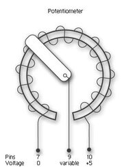
With all of this information, I set out to re-index the potentiometer gear (it's the blue one in the pics) on the actuator. Since the potentiometer is just a variable resistor, I used a multimeter to test the resistance. I tested from pins 7 to 10 on the actuator and got ~8K ohms. I tested from pins 7 to 9 and 9 to 10 and got ~0.1k ohms and ~7.9k ohms this indicated that the potentiometer was not centered. I also bought a replacement actuator as a backup just in case. I tested my theory on the new actuator and I got 3.5k ohms on pins 7 and 9, and ~5.6k ohms on pins 9 and 10. They are both fairly close so it's about centered electronically.
View attachment 20909
After opening the old actuator, I checked for cracked or broken gears or motors and they were all intact. The output shaft was also secure to the output gear. If anything is broken or cracked this procedure may not work. You may be able to repair the cracked gear (I've seen a post on this somewhere), but if it breaks loose you will be back in the same position.
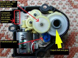
Moving on, I pulled the gear in the middle which mates the output gear to the gears on the motor. I also pushed the output shaft into the casing so it was disengaged from the blue gear. Then I was able to turn the blue gear continually and tested pins 7 to 9 and 9 to 10 until they both read approximately the same resistence (which ended up to be around 4.3k ohms). This ensured that at least the potentiometer gear was approximately centered. I pushed the output gear back in place and meshed it with the blue gear. You'll want to make sure that the bottom of the white plastic piece on the outside is horizontal (so it will mesh with the gear in the truck for the air flow door) to the bottom of the actuator case. I basically looked at the new actuator and tried to match it's position. I then pushed the middle gear back into the actuator and closed up the case.
I ended up doing the above twice for the following reason. I didn't know the gear in the truck which moves the air flow door is in the top most position (which I believe sets the air flow to the floor vents) it also felt like the gear in the truck was spring loaded. This is where the position of the white plastic piece is important. I also learned from my first failed attempt that the calibration cycle moves the plastic piece down first then back up (i.e. the output shafts moved clockwise then counter clockwise when looking at the connector side of the actuator).
I put the actuator back in the truck and felt the mesh of the white plastic piece and the gear in the truck. There was a slight gap at the bottom of the white plastic. Since it's a pain to reposition everything in the acutator I tried it in the truck anyway. I bolted the actuator in and inserted the actuator plug. I then replaced the negative battery cable and turned the ignition to ON and let it sit for about 2 minutes. I then turned on the blower and air was coming from both the dash and floor vents. IT WORKED!!! I tested all the modes, recirculation, the defrost vent, and both temperatures (since everything works via an actuator). Everything was good!!!
I hope this saves some folks some $$$$. I also want to thank the roadie for his explaination of the actuator.
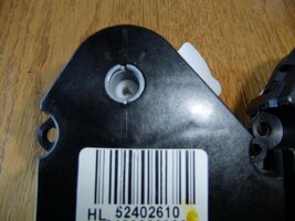
Front of old actuator
View attachment 20907
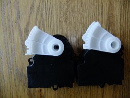
Old on left and new on right. You can use this for comparing the location of the white plastic piece.
View attachment 20908
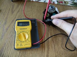
Tested the resistance between pins 9 and 10.
View attachment 20910
The opened actuator. I borrowed this from the roadie's post.
View attachment 20911
So after reading this thread (No floor vents - replaced mode actuator - rebuilt defrost actuator still nothing - Chevy TrailBlazer, TrailBlazer SS and GMC Envoy Forum) from the roadie, I started to understand the design flaws of the actuator which causes our issue.
Based on the roadie's post, I learned that the actuator is just like a servo (like one for remote control cars). It has a potentiometer which moves when the output shaft on the actuator moves. This allows the HVAC control module to determine the position of the actuator at any point in time. The potentiometer signal is used during calibration to determine the how far the actuator needs to move from end to end. The feedback from the potentiometer is stored so the HVAC control module can use it when moving the actuators in the future (until the battery is disconnected from the HVAC module). Based on the roadie's observations, the actuator moves passed the end point of the potentiometer and the HVAC control unit reads this as a short and becomes confused.
With all of this information, I set out to re-index the potentiometer gear (it's the blue one in the pics) on the actuator. Since the potentiometer is just a variable resistor, I used a multimeter to test the resistance. I tested from pins 7 to 10 on the actuator and got ~8K ohms. I tested from pins 7 to 9 and 9 to 10 and got ~0.1k ohms and ~7.9k ohms this indicated that the potentiometer was not centered. I also bought a replacement actuator as a backup just in case. I tested my theory on the new actuator and I got 3.5k ohms on pins 7 and 9, and ~5.6k ohms on pins 9 and 10. They are both fairly close so it's about centered electronically.
View attachment 20909
After opening the old actuator, I checked for cracked or broken gears or motors and they were all intact. The output shaft was also secure to the output gear. If anything is broken or cracked this procedure may not work. You may be able to repair the cracked gear (I've seen a post on this somewhere), but if it breaks loose you will be back in the same position.
Moving on, I pulled the gear in the middle which mates the output gear to the gears on the motor. I also pushed the output shaft into the casing so it was disengaged from the blue gear. Then I was able to turn the blue gear continually and tested pins 7 to 9 and 9 to 10 until they both read approximately the same resistence (which ended up to be around 4.3k ohms). This ensured that at least the potentiometer gear was approximately centered. I pushed the output gear back in place and meshed it with the blue gear. You'll want to make sure that the bottom of the white plastic piece on the outside is horizontal (so it will mesh with the gear in the truck for the air flow door) to the bottom of the actuator case. I basically looked at the new actuator and tried to match it's position. I then pushed the middle gear back into the actuator and closed up the case.
I ended up doing the above twice for the following reason. I didn't know the gear in the truck which moves the air flow door is in the top most position (which I believe sets the air flow to the floor vents) it also felt like the gear in the truck was spring loaded. This is where the position of the white plastic piece is important. I also learned from my first failed attempt that the calibration cycle moves the plastic piece down first then back up (i.e. the output shafts moved clockwise then counter clockwise when looking at the connector side of the actuator).
I put the actuator back in the truck and felt the mesh of the white plastic piece and the gear in the truck. There was a slight gap at the bottom of the white plastic. Since it's a pain to reposition everything in the acutator I tried it in the truck anyway. I bolted the actuator in and inserted the actuator plug. I then replaced the negative battery cable and turned the ignition to ON and let it sit for about 2 minutes. I then turned on the blower and air was coming from both the dash and floor vents. IT WORKED!!! I tested all the modes, recirculation, the defrost vent, and both temperatures (since everything works via an actuator). Everything was good!!!
I hope this saves some folks some $$$$. I also want to thank the roadie for his explaination of the actuator.
Front of old actuator
View attachment 20907
Old on left and new on right. You can use this for comparing the location of the white plastic piece.
View attachment 20908
Tested the resistance between pins 9 and 10.
View attachment 20910
The opened actuator. I borrowed this from the roadie's post.
View attachment 20911