Rebuilding Transfer Case in a 2003 Envoy / GM226HD

flydude92

Original poster
Member
Feb 23, 2015
8
I recently rebuilt the transfer case (model GM226HG) in my wife’s 2003 Envoy SLE with 155,000 miles. She had been getting a loud whining sound from it about 6 months ago. She’s a smart girl and would only use it in 2WD to prevent further damage which worked really well since it was close to coming apart. I realize you can get used cases for a couple hundred dollars although you never know what you will get. Naturally if you are pressed for time purchasing a rebuilt or used case may be your only option. I decided to rebuild it since I like a challenge. I removed the transfer case and took it apart taking pictures so I would remember how to put it back together. In the meantime I found a .pdf file online describing how to disassemble and reassemble it.

http://sult.us/MYISUZU/2004 DRIVELINE AXLE Transfer Case.pdf

I used it to reassemble the transfer case and it helped make the task much easier. Read thru it to make sure you can buy, borrow or make the tools you need. I found it fairly easy to rebuild with no real surprises. It would help to have a press to remove bearings or the ability to adapt other tools as needed. A tool to remove the retaining rings would be nice (I used regular snap ring pliers) and a gear puller to remove the rear output shaft speed reluctor wheel. I purchased a couple tools real cheap on EBay but could have gotten by without them. There wasn’t anything to adjust. Just put the parts back together. I took the case completely apart and replaced all the bearings, seals and a few other parts that were worn out or damaged.

Some parts I found on EBay and others are only available from the dealer. For example, one bearing from the dealer was $119 and I purchased it on EBay new for $25 including shipping. The dealer gave me around 20% off the parts I purchased from them.
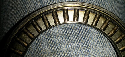
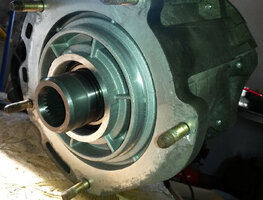
20150202_152230.jpg
This is the undersized pressure plate bearing that was causing the whining sound. When this goes the rest of the case soon follows.

I will post assembly pictures as soon as I get them prepared. Should take a couple days.
 
  • Like
Reactions: Mounce

Bow_Tied

Member
Dec 21, 2014
453
London, ON
Looks like some spalling there, maybe some heat tint. Did it ever run low on oil?

Looking forward to the mentioned pics.
 

flydude92

Original poster
Member
Feb 23, 2015
8
No, I never ran low on oil.

I am working on the pictures as I write this.

I plan to have them ready tonight or tomorrow.
 

flydude92

Original poster
Member
Feb 23, 2015
8
I‘ve attached a few pictures I took while assembling the transfer case.
I didn’t get a picture of every step but I believe they will help.
I purchased a 10 piece bearing race and seal driver set from Harbor Freight
to help remove and install bearings along with some of the seals.
If you follow the .pdf file you shouldn’t have any problems rebuilding your
transfer case.


Transfer Case 5.jpg
[SIZE=12pt]The new input gear bearing installed in the left side of the front case. This was the hardest bearing to[/SIZE]
[SIZE=12pt]install because of its size. I had trouble getting it to go in straight. When it was about half way in it[/SIZE]
[SIZE=12pt]became easier to install.[/SIZE]


[SIZE=12pt]Transfer Case 10.jpg[/SIZE]
[SIZE=12pt]The new front output shaft bearing in the front case (sorry about the picture - the bearing is on the left)[/SIZE]


[SIZE=12pt]Transfer Case 15.jpg[/SIZE]
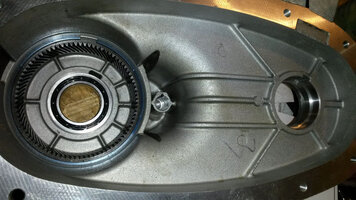
[SIZE=12pt]The planetary gear assembly installed in the front case. Make sure the large diameter thrust washer[/SIZE]
[SIZE=12pt]is installed correctly before installing the gear assembly. (see the .pdf)[/SIZE]


Transfer Case 20.jpg
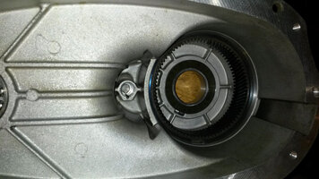
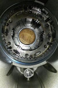
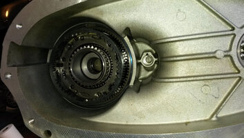
[SIZE=12pt]This picture shows the input gear assembly installed in the planetary gear assembly. Again make[/SIZE]
[SIZE=12pt]sure the thrust washer is positioned properly. Before installing the input gear I replaced the seal and[/SIZE]
[SIZE=12pt]thrust bearing in it. The input gear didn’t take much pressure to remove or install.[/SIZE]


Transfer Case 25.jpg
[SIZE=12pt]This picture shows the input gear assembly from the outside of the case. I replaced the bearings in this[/SIZE]
[SIZE=12pt]assembly because it was hard to turn. It now turns very easily.[/SIZE]


Transfer Case 30.jpg
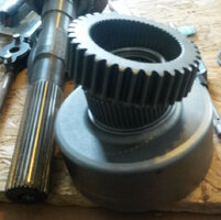
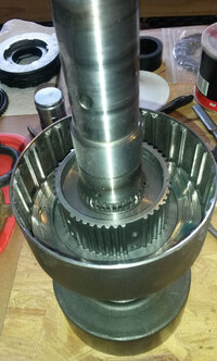
[SIZE=12pt]Picture of the new clutch housing with the drive sprocket. I replaced the clutch housing due to steps[/SIZE]
[SIZE=12pt]being worn into the housing disc teeth which would cause problems shifting smoothly.[/SIZE]


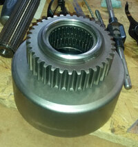
Transfer Case 35.jpg
[SIZE=12pt]The new clutch housing with the drive sprocket and retaining ring installed[/SIZE]


[SIZE=12pt]Transfer Case 40.jpg[/SIZE]
[SIZE=12pt]It’s a little difficult to see but this picture shows the rear output shaft thrust washer and[/SIZE]
[SIZE=12pt]clutch housing retaining ring installed above the clutch housing. I replaced the thrust washer[/SIZE]
[SIZE=12pt]because the two teeth on it were worn down and the washer would rotate on the shaft.[/SIZE]


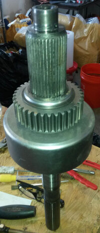
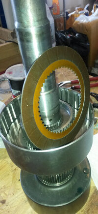
[SIZE=12pt]Transfer Case 45.jpg[/SIZE]
[SIZE=12pt]Picture of the new clutch housing with the clutch hub and an outer and inner clutch disk installed.[/SIZE]
[SIZE=12pt](the shaft is standing inside the old clutch housing) None of the disks showed signs of wear. The[/SIZE]
[SIZE=12pt]directions didn’t mention this but I coated each disk with transfer case fluid before installing them.[/SIZE]


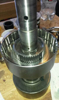
Transfer Case 50.jpg
[SIZE=12pt]Clutch housing with an inner clutch disk[/SIZE]
 

flydude92

Original poster
Member
Feb 23, 2015
8
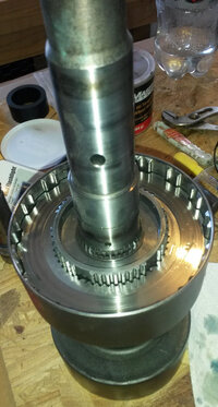
[SIZE=12pt]Transfer Case 55.jpg[/SIZE]
[SIZE=12pt]A couple more clutch disks are installed. The top disk is an outer clutch disk.[/SIZE]


Transfer Case 60.jpg
[SIZE=12pt]Picture of the last clutch disk installed. 9 inner and 9 outer clutch disks for a total of 18.[/SIZE]


Transfer Case 65.jpg
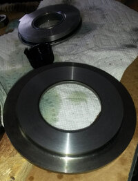
[SIZE=12pt]This is the clutch apply plate. I was told by the dealer that this plate came with the redesigned[/SIZE]
[SIZE=12pt]pressure plate bearing. (top of picture) It doesn’t. It seems the bearing spun against this plate causing[/SIZE]
[SIZE=12pt]some damage to the plate. I found this out on a Friday as I was putting the transfer case back together.[/SIZE]
[SIZE=12pt]The part was $65 and I wouldn’t get it until Monday afternoon. I didn’t want to wait so I turned it on[/SIZE]
[SIZE=12pt]my lathe and only took .008” off to get it smooth so I installed it. The redesigned pressure plate bearing[/SIZE]
[SIZE=12pt]assembly (at the top) is the same depth but a larger outer diameter then the original.[/SIZE]


[SIZE=12pt]Transfer Case 70.jpg[/SIZE]
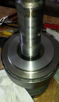
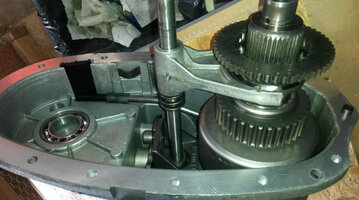
[SIZE=12pt]Clutch housing with the apply plate installed. The clutch spring was also installed under the[/SIZE]
[SIZE=12pt]apply plate but isn’t shown.[/SIZE]


Transfer Case 75.jpg
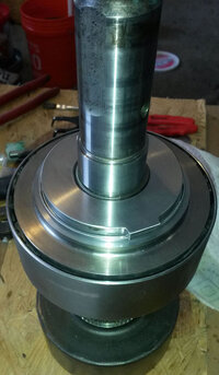
[SIZE=12pt]Clutch assembly with the apply plate, pressure plate bearing, clutch inner plate and retaining[/SIZE]
[SIZE=12pt]ring installed.[/SIZE]


Transfer Case 80.jpg
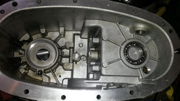
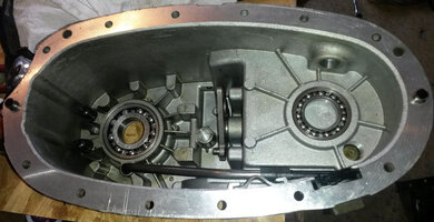
[SIZE=12pt]New output shaft rear bearing installed in the rear case half. A new control actuator lever shaft bearing[/SIZE]
[SIZE=12pt]was also installed. Not sure if you can see it but it is installed horizontal in the center of the case. The [/SIZE]
[SIZE=12pt](‘V’ shaped) chip collector magnet is also installed. (bottom right)[/SIZE]


Transfer Case 85.jpg
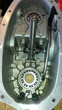
[SIZE=12pt]New rear output shaft bearing installed on the left. The picture also shows the control actuator lever[/SIZE]
[SIZE=12pt](in the center) and the oil pump screen (bottom right), oil pump hose & pump suction pipe installed.[/SIZE]


[SIZE=12pt]Transfer Case 90.jpg[/SIZE]
[SIZE=12pt]Here we have the shift fork shaft installed with the bottom retaining ring. I put a little[/SIZE]
[SIZE=12pt]transfer case fluid on the bottom of the shaft.[/SIZE]


[SIZE=12pt]Transfer Case 95.jpg[/SIZE]
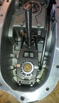
[SIZE=12pt]The redesigned clutch lever installed[/SIZE]


Transfer Case 100.jpg
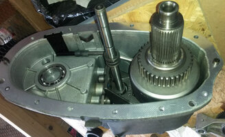
[SIZE=12pt]The rear output shaft assembly installed in the rear case half.[/SIZE]
 

flydude92

Original poster
Member
Feb 23, 2015
8
[SIZE=12pt]Transfer Case 105.jpg[/SIZE]
[SIZE=12pt]This picture shows the bottom spring, range sleeve on the input gear and the shift fork on the shift[/SIZE]
[SIZE=12pt]fork shaft.[/SIZE]


Transfer Case 115.jpg
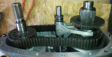
[SIZE=12pt]Here we have the top shift fork spring and the retaining ring along with the front output shaft and driven[/SIZE]
[SIZE=12pt]sprocket installed on the left with the chain. The chain was placed on the drive[/SIZE]
[SIZE=12pt]sprocket on the rear output shaft (on right) then placed on the driven sprocket on[/SIZE]
[SIZE=12pt]the front output shaft as the front output[/SIZE]
[SIZE=12pt]shaft (on left) was installed. [/SIZE]


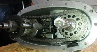
Transfer Case 120.jpg
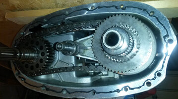
[SIZE=12pt]Another view of the completed rear case half.[/SIZE]


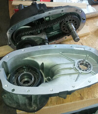
Transfer Case 125.jpg
[SIZE=12pt]A picture of both halves ready to be reconnected[/SIZE]


Transfer Case 135.jpg
[SIZE=12pt]1/8” bead of silicone gasket maker on the case half.[/SIZE]


[SIZE=12pt]Transfer Case 140.jpg[/SIZE]
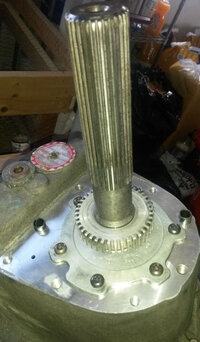
[SIZE=12pt]Picture of the reluctor speed wheel installed on the rear output shaft. I bought a special[/SIZE]
[SIZE=12pt]tool on EBay to install this gear and it broke. The tool would not have broken if I heated[/SIZE]
[SIZE=12pt]the gear first or if it was designed better. If you don’t have the tool you can use a pipe[/SIZE]
[SIZE=12pt]to install it. In this case I would install the gear before putting the halves together[/SIZE]
[SIZE=12pt]so you can support the back of the shaft. Heating the gear with a propane torch did make[/SIZE]
[SIZE=12pt]it easier to install.[/SIZE]


Transfer Case 145.jpg
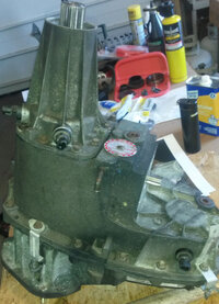
[SIZE=12pt]Both halves connected with the rear extension installed with 3 sensors and 2 cable mounting brackets. [/SIZE]


Transfer Case 150.jpg
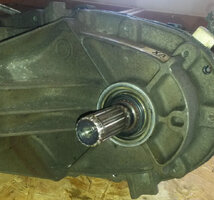
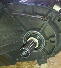
[SIZE=12pt]Front output shaft seal installed[/SIZE]


Transfer Case 155.jpg
[SIZE=12pt]Front output shaft dust seal installed[/SIZE]


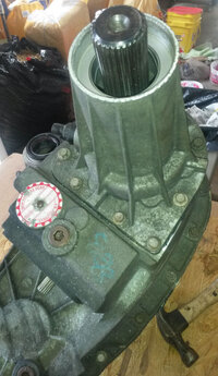
Transfer Case 160.jpg
[SIZE=12pt]Ready to install the rear output shaft seal[/SIZE]


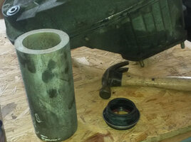
[SIZE=12pt]Transfer Case 165.jpg[/SIZE]
[SIZE=12pt]I was lucky. I found this pipe lying around that fit the seal perfectly.[/SIZE]


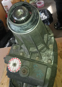
Transfer Case 170.jpg
[SIZE=12pt]The rear output shaft seal installed. Make sure you install it with the hole pointing down. The hole[/SIZE]
[SIZE=12pt]is on the right side of the seal.[/SIZE]

Enjoy
 

Forum Statistics

Threads
23,336
Posts
638,040
Members
18,541
Latest member
33chevyrod