may be your solution to bypass
I have seen writeups for doing the bypass like this but I always wondered if the BCM might toss a code when it sees the dropped voltage when it should be seeing the nominal 5 volt signal. Maybe they did not write that check into the BCM firmware/calibration?
I had thought that were I to do a bypass of this sort I would at least try to use a relay that would allow me to duplicate the entire factory setup, that of 5 volt signal until turned to CRANK then drop in the resistor and hold it in until key off.
However, there is something in my DNA that compels me to fix things instead of seeking to bypass them.
Just last week I repaired my old coffee pot after buying a new one. I had already identified the failure before buying the new unit but could not bring myself to toss out the old pot when I saw I could fix it for a few dollars.
Anyhow, if anyone reading this far is thinking of doing this on our GMT360/370 the wiring is easier to get to. I'll toss up some images here and add a few of the sensor itself which you cannot see without destroying it and the housing to get it out.
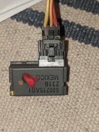
First off here is our sensor and the three wires.

Here is a look at the magnet in the lock cylinder, a passlock sensor with the area that is sensing the magnet circled, and the actual circuit board from inside a sensor showing the semiconductor(s) that do the sensing circled.

A close up of the circuit board with the actual resistor that is switched in circles in blue. You can sort of see there are TWO sensing elements layered one atop the other the lower one is the tamper sensor that trips if the magnetic field strength is too high.

And lastly, I would imagine the same bypassing of the sensor could also be done back at the BCM under the rear seat?? Same wires are available there without having to tear apart the steering column. However the wires are taped up pretty good there and you would likely want to remove the connectors from the BCM and unwrap some tape to gain adequate access.
I tried to isolate the wires for the first of the next 2 pictures. The sensor signal wire is on C1, terminal B10. The low reference (ground) is on C2, terminal E8 and the 12 volt power is right next to that at C2, E9.

Here below is the yellow sensor signal wire on the bottom connector, the row closest to the front of the truck and down low towards the floor. You can just barely see it between that orange wire and the black/white wire. Not easy to access without removing the connector from the BCM.