P0135

JayArr

Original poster
Member
Sep 24, 2018
504
Mission BC Canada
Hi All
On vacation with the Envoy pulling our trailer up north to Yellowknife. The transmission I rebuilt is working like a champ but I'm getting random P0135 and P0053 codes. I changed the oxygen sensor in the exhaust manifold but they keep coming so I think I have a broken wire somewhere in the engine loom between the sensor and the PCM.

I don't have the time or patience to tear into the wiring looking for a bad connection out here in the field so my idea is to buy a spool of wire and cut a few inches back from the O2 connector and run brand new wires over to the PCM, cut the four over there and atttach. This should bypass the wire break, wherever it is, and let me finish my holiday without codes.

I do carry a portable butane soldering iron with me in the trailer so I can get good splices. Can anyone help me with a link or a .pdf of the wiring? (I don't carry my paper manuals with me on holiday) I need to know where the four wires connect to the PCM.

2005 Envoy XL.
 

Reprise

Lifetime VIP Donor
Supporting Donor
Member
Jul 22, 2015
2,724
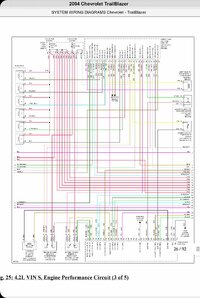
Took a bit to find this for the 4.2L PCM. These are in two different blocks on the PCM (and it's from the 2004 schematic, fig 24 - 4.2L VIN S, Engine Performance Circuit 2 of 5)

See if it matches to what you've got...


30 pin connector

18 - Tan/White H02S Lo Sig B1 S2

23 - Purp / Wht - H02S Hi Sig B1 S1

(reference: 24 is unused, 25 is Lt Grn)

26 - Purp / Wht - H02 Hi Sig B1 S2


35 pin connector (30-65; 30-32 are the first three on the block, LH side)

30 - Black / Wht - H02S Htr Lo B1 S2

31 - Dk Grn - H02S Htr Lo B1 S1

32 - Tan - H02S Lo Sig B1 S1

(reference: 33 is unused, 34 is Lt Blu / Wht)

Pink wires on both sensors are FUSED


One more thing: When I was towing last month, my B1S2 (rear) sensor threw a code after a few hours when the engine was under load. Went away next morning after cooldown. Came back after loading the engine again. If your rear sensor is what's giving you the code, you may have a similar issue. (e.g.; I *don't* think you'd have a break in the wiring)
 
Last edited:

mrrsm

Lifetime VIP Donor
Supporting Donor
Member
Oct 22, 2015
7,750
Tampa Bay Area
To Safely, Properly Test and Verify the O2 Sensor Heater (Current) and the Circuitry::


Last edited:

Mooseman

Moderator
Dec 4, 2011
25,355
Ottawa, ON
And just because it's new, doesn't mean it's good. If you had the exact same codes prior, yes, I would suspect the wiring, however, would suspect the new sensor.

A code P0135 may mean that one or more of the following has happened: O2 Heater element resistance is high Internal short or open in the heater element O2 heater circuit wiring high resistance open or short to ground in the wiring harness

Potential causes of a P0053 trouble code may include: A faulty O2 sensor Burnt, broken, or disconnected wiring and/or connectors Blown fuse or burnt fusible link Defective engine control relay


What brand sensor did you use? I wouldn't bother with trying to fix it in the field since it's just for the heater, which doesn't come into play once it's hot from the exhaust.
 

JayArr

Original poster
Member
Sep 24, 2018
504
Mission BC Canada
I used a BDW sensor and got the exact same codes immediately after.

When I put up the O2 sensor on the torque pro and watched it I could see it cutting in and out. Sometimes it would cyscle properly, sometimes it would get stuck at zero. If I'm sitting idling and it gets stuck on zero I can rev the engine and it will start working again. I'm pretty sure it's a broken wire inside the insulation that is intermittantly connecting and disconnecting.

Once I'm out on the highway it runs great.

I'm in a campsite on Lessor Slave Lake so it's a make it work sort of scenario. I grabbed three 25 foot rolls of wire and some heat shrink from Napa in Edmonton before we left. I'll let you know how this works out.

JayArr
 

Mooseman

Moderator
Dec 4, 2011
25,355
Ottawa, ON
Makes sense that at idle, it relies on the heater to make it work at the required 600f. At higher speed, it would reach that with the exhaust heat.

Did you check at the connector if the PCM is sending 12v to the two wires for the heater? How about the resistance of the heater on the sensor? I'd hate for you to muck around the wiring and it's another bad sensor.

This video shows some tests you can do:

 
  • Like
Reactions: budwich

JayArr

Original poster
Member
Sep 24, 2018
504
Mission BC Canada
Well, I ran four parallel wires from the plug where the O2 sensor connects. Three of them went to the pcm and the fourth went to the O2 fuse..

No change!

So that disproves my theory that it was a broken wire in the harness.

No harm done the vehicle still runs as before.

I was curious to know if the code was because the current was below 0.25A or above 3.15A but I couldn't find a way to monitor O2 current using Torque Pro so I pulled out the Tech II. It shows the individual currents of the two sensors in one of the data menus. Sure enough there was no current on the forward sensor heater. The rear heater was alternating on/off and drawing about 0.65A.

I double checked that there was 12V reaching the sensor and there was. I checked the resistance of the sensor and it is 16 ohms. I even pulled the O2 fuse and the pcm connector and measured the same resistance between the power source point and where the other side of the heater connects to the pcm.

I am running out of tests and I am starting to think there is a problem in the pcm.

Any thoughts or suggestions welcome.

Jayarr
 

Mooseman

Moderator
Dec 4, 2011
25,355
Ottawa, ON
Maybe the sensor quits only at higher temps while driving? I dunno. Seems like a weird one but can't see the PCM as being at fault but have been proven wrong before on that. These are getting old. If you have a spare PCM or can get one cheap at a pick-n-pull yard, sure.
 

JayArr

Original poster
Member
Sep 24, 2018
504
Mission BC Canada
I do have a spare pcm but it's at home. I have had thoughts before that I should program it to match the one in the car and carry it as a spare but I never got around to it.

When I get a chance I'll pull the fuse and pcm connector and apply 12v to the pink wire and I'll ground the green wire and measure the current. if it's within spec I'll wait until I get home and swap PCMs.

These O2 sensors are powered all the time by connection to 12VDC switched on with IGN. They are what I call "switched to ground" in that they are turned on by having the other end connected to ground to complete the path. This is done in the PCM by what is commonly referred to as an "open collector" driver.

Since the current is also monitored the circuit probably also contains a very low value shunt resistor that the current must pass through on it's way to ground and the PCM can determine the current by measuring the voltage accross the shunt. This is a pretty common electronic circuit configuration in instrumentation.

It's possible that either the "open collctor" driver or the shunt resistor are damaged or that some solder connection along the way has cracked and opened.

It's aslo possible that I'm way off base and it's something else entirely.

It's sure fun trying to figure it out!

More to come.

JayArr
 
  • Like
Reactions: Mooseman

TJBaker57

Member
Aug 16, 2015
2,902
Colorado
These O2 sensors are powered all the time by connection to 12VDC switched on with IGN. They are what I call "switched to ground" in that they are turned on by having the other end connected to ground to complete the path. This is done in the PCM by what is commonly referred to as an "open collector" driver.

This may not be worth much but in my benchtop PCM resistance tests the C2/31 terminal (B1,S1 lo) reads from 850k to 870k to ground. Tested on 3 different P10 PCMs.
 

JayArr

Original poster
Member
Sep 24, 2018
504
Mission BC Canada
That's worth a lot, I'll test that.

Out of curiosity, do you get the same resistance if you reverse the red and black leads? That will indicate wheter the path to ground goes through a forward biased silicon junction (a diode or a transistor).

Also: Does the B1S2 low pin on the pcm measure the same to ground? (I would expect them to be similar)
 

TJBaker57

Member
Aug 16, 2015
2,902
Colorado
That's worth a lot, I'll test that.

Out of curiosity, do you get the same resistance if you reverse the red and black leads? That will indicate wheter the path to ground goes through a forward biased silicon junction (a diode or a transistor).

Also: Does the B1S2 low pin on the pcm measure the same to ground? (I would expect them to be similar)

For the reverse direction I will check this when I return to the house this evening. I remember checking some pins in the reverse direction but I didn't record the results.

Yes, the B1S2 l9 measures the same as B1S1 lo.
 

TJBaker57

Member
Aug 16, 2015
2,902
Colorado
@JayArr

So if I use the same multimeter, an old craftsman with a max selection of 2000k, NOT an autoranging model and read reverse it starts at about 388k and slowly drops. After about 30 to 45 seconds it gets to say 380k. I haven't waited any longer to see how low it would go.

Both sensor lo pins behave the same.

Added note in edit: readings were done with ALL power removed from the PCM, even the always hot supply.

Here's the 'thing' that has always puzzled me about reading resistance in situ of a circuit. I have two autoranging multimeters and an older Craftman manual selection model. I can get no agreement on those two autoranging models. In the reverse direction one read about 15 megohms and the other about 8 megohms. In the forward direction one reads 28 megohms and the other reads open circuit (maybe beyond its range?).

All meters read a 1 megohm resistor just fine.
 

JayArr

Original poster
Member
Sep 24, 2018
504
Mission BC Canada
I don't like autoranging multimeters and avoid them when possible. They are more like toys and appeal to guys that don't have a lot of experience and hope the meter will do all the work. They always seem flakey to me, taking a long time to decide what range they should be on. The delay can even be dangerous in a testing environment, I watched one tech smoke an inverter waiting for the meter to tell him he was overcurrent. A regular needle meter tells you that immediately and you power down LOL. TBH I don't even like digital meters much and my daily meter is an old Simpson 260 (with a needle).

(if you put a $10 analog/needle meter and a $500 autoranging Fluke on the table I'd take the analog)

Resistance is measured by sending a current through the circuit, that's what the battery in the meter is for. As the battery ages the resistance can vary slightly but not much.

What can change from meter to meter and even from one resistance range to the next is the voltage applied by the meter to the circuit. If the voltage applied is above 0.6 or 0.7VDC it'spossible for a meter to forward bias a semiconductor junction and turn it 'on'. This is easy to see by taking a common diode and measuring it. On my meter I get a reading of about 15 ohms 'forward biased' and infinite ohms 'reverse biased'

Here's how this becomes useful. If you measure a resistance in circuit or 'in situ' as you described and if you then reverse your leads and get the same reading then you are probably reading a purely resistive component.

If the reading changes when you reverse the leads then the lower reading might be through a semiconductor junction.

Example: Take a 1kohm resistor and a general purpose diode and twist them together in paralell. Now when you read them forward biased you may get a reading around 15 ohms because most of the current the meter sends out is going through the diode. Reverse the leads and you will read 1kohm because the diode is reverse biased and 'off' or non conducting so the meter current must all flow through the resistor.

I don't know what to make of the 380k versus 850k but it's good to know both numbers when comparing.

JayArr
 
  • Like
Reactions: azswiss

JayArr

Original poster
Member
Sep 24, 2018
504
Mission BC Canada
Back to this problem today. I'm still getting the codes and the heater in the forward O2 sensor is not coming on despite it and the wiring being OK.

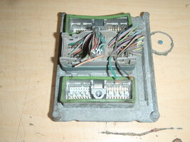
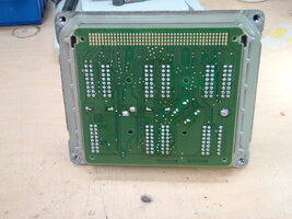
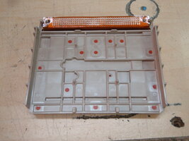
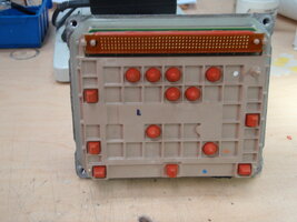
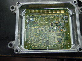
My conclusion is that it's a PCM fault. I have a spare PCM that came with the engine I bought so I opened it up this morning to see what I can see. It's a multi layered unit with the inputs connected to a circuit board that has no active components, just the connections to the physical world.

There is a mylar/foil ribbon cable that connects the input circuit board to the active circuit board where all the action happens. The connections are all just pressure contact when the case is bolted together so everything comes out nice and easy.
 

Attachments

  • P9170004.JPG
    P9170004.JPG
    583.3 KB · Views: 1
  • P9170005.JPG
    P9170005.JPG
    405.8 KB · Views: 1
  • P9170006.JPG
    P9170006.JPG
    433 KB · Views: 1
  • P9170007.JPG
    P9170007.JPG
    353.6 KB · Views: 1
  • P9170008.JPG
    P9170008.JPG
    638 KB · Views: 1
  • Like
Reactions: Mooseman

JayArr

Original poster
Member
Sep 24, 2018
504
Mission BC Canada
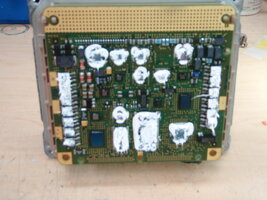
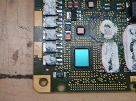
I followed C2 pins 30 and 31 (O2 heater circuits) into the PCM and through the ribbon connector and all the way down to the lower left of the circuit board where they attach to two Field Effect Transistos (FETs). the output of the FETs go through 0.1 ohm reistors to ground.

The FETs are the lower two in the bottom left corner and the resistors are the grey rectangular components that say "DALE R1"
 

Attachments

  • P9170009.JPG
    P9170009.JPG
    383.8 KB · Views: 1
  • P9170010.JPG
    P9170010.JPG
    482.1 KB · Views: 1

JayArr

Original poster
Member
Sep 24, 2018
504
Mission BC Canada
Here's how the circuit works:

Power is applied to both heaters from O2 fuse 29, these are the pink wires. They provide 12VDC to the heaters in run or start. This power is not controlled or turned on/off by the PCM, it's just there.

To turn the heater on the PCM applies a signal to the gate (G) of the FET that is connected to the appropriate sensor. This turns on the FET and it acts like a switch completing the circuit to ground and allowing current to flow from the fuse, through the heater, through the FET and finally through the resistor to ground. At this point the heater will be 'on'.

The DALE R1 resistors are there for one specific reason, so the PCM can measure how much current is going through the heater. They are a very small value - 0.1ohm - so they don't materially affect the circuit or the heater but by knowing the resistance and measuring the voltage across it the PCM and calculate the heater current.

Typical heater current is 0.65Amps and at this current draw the voltage measured across the resistor would be 65 mV. Quite easy for a microprocessor to measure.

In my PCM the forward heater does not turn on so one (or mor) of three problems can exist.

1) the signal to the gate of the FET is not being supplied
2) the FET has stopped working
3) the resistor is burned out or the solder connection has opened.

My guess is 3)
 

Attachments

  • O2PCM.pdf
    154.3 KB · Views: 4

JayArr

Original poster
Member
Sep 24, 2018
504
Mission BC Canada
So this has all been fun but I'm hesitant to just pull the PCM off my running daily driver and open it up. If something went wrong I would be out of cars right now.

Is there a way to copy the PCM that's in the car to the spare I have (settings, VIN, Odometer and all) so that if I can't fix the one in the car the spare will run the car?

I have a Tech 2 clone.

If I can get the PCM 'backed up' I'll pull the PCM from the car and see if I can repair the FET circuit for O2 sensor #1 so the heater starts working again.

These PCMs have been pretty bulletproof so far but as this platform ages they may start to show more and more faults and knowing how to repair them would be handy.
 
  • Like
Reactions: TJBaker57

Mooseman

Moderator
Dec 4, 2011
25,355
Ottawa, ON
I don't think you can "backup" the PCM. All you can do is program the other PCM with your VIN using Tis2000. You will still need to do the 30 minute security relearn.
 

TJBaker57

Member
Aug 16, 2015
2,902
Colorado
my PCM the forward heater does not turn on

Shall I guess you used the Tech 2 to turn on the forward heater and saw no appropriate amperage reading?

And verified power at PCM connector 2, pin 30 feeding through the heater circuit from the fuse?


Power is applied to both heaters from O2 fuse 29, these are the pink wires. They provide 12VDC to the heaters in run or start.

My diagrams show this power hot at all times. Have not verified this in a vehicle.


Adding a quick edit to say the odometer is maintained in the Cluster so this is not an issue with changing a PCM.
 
Last edited:

JayArr

Original poster
Member
Sep 24, 2018
504
Mission BC Canada
Shall I guess you used the Tech 2 to turn on the forward heater and saw no appropriate amperage reading?

And verified power at PCM connector 2, pin 30 feeding through the heater circuit from the fuse?
Yes and yes.

Also, if I use an extra wire from pin 30 to ground the heater turns on and I can measure that there is current flow - indicating that the heater is OK.

My diagrams show this power hot at all times. Have not verified this in a vehicle.

Look at the diagram you posted in post#4 of this thread. "hot in run and start"

I don't think you can "backup" the PCM. All you can do is program the other PCM with your VIN using Tis2000. You will still need to do the 30 minute security relearn.

Can I program a 2003 PCM to be a 2005 PCM with a new VIN?
 
  • Like
Reactions: TJBaker57

TJBaker57

Member
Aug 16, 2015
2,902
Colorado
Look at the diagram you posted in post#4 of this thread. "hot in run and start"

Ah, I looked at a 2002 wiring diagram yesterday and that 2002 diagram has an error. It shows "Hot at all times" on the engine wiring page but the power distribution diagram shows it going through the ignition switch terminals B and C which are hot in Run and Start. This is not the first of such errors I have stumbled across.


Can I program a 2003 PCM to be a 2005 PCM with a new VIN?

This I don't know for certain. A number of suppliers listings suggest it can work but then some suppliers list PCMs that fit from 2002 to 2007 which cannot be right since they used 2 different PCMs in that time span.
 

Mooseman

Moderator
Dec 4, 2011
25,355
Ottawa, ON
Can I program a 2003 PCM to be a 2005 PCM with a new VIN?
From what my research shows, 03-05 use the same PCM. Just need to load it with the 2005 VIN calibrations.
 

Forum Statistics

Threads
23,336
Posts
638,065
Members
18,543
Latest member
chriswilson5585

Members Online