Hello everyone,!!I spend two days reviewing all the installation guide we have here..( blazinlow89 thread and awer25 in trailvoy.) and I read all the reply of great MAY03LT.. But I have connections that I dont know where to connect..  Hope you guys can help me., I know its easy to bring it to installer and pay $$$.. But for me If I can do it,why not? and to save as well.. ( Everytime I accomplish something by myself,( w/ the help of others. ) It makes me proud and happy..
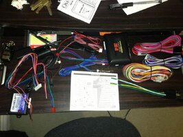
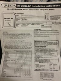
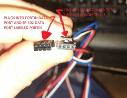
So what I have is Crime Stopper SP-502 and OMEGA DB-GMDL-BP bypass..
View attachment 28804
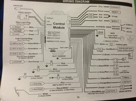
And as I understand from MAY03LT connection from blazinlow89 thread, my connections are:
View attachment 28805
(LEFT SIDE)
Status LED
Shock Sensor
* Door Lock Plug (White 3 PinS Plug)
BLUE (UNLOCK (-) ) = ?
RED ( 12V ) FOR RELAYS = ?
GREEN (LOCK (-) ) = ?
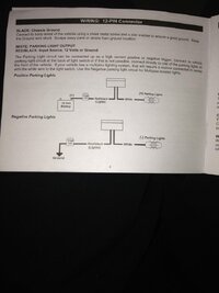
*LOW CURRENT PLUG (Blue 4 PinS Plug)
GREEN&WHITE (-) IGN/AUX = ?
VIOLET&WHITE (-) ACC/AUX3 = ?
BLUE&BALACK (-) RUN/AUX2 = ?
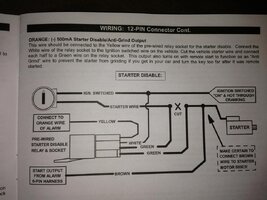
BLUE/ORANGE (-) STARTER = ?
*OMEGA DB-GMDLBP
BROWN(NEG GND WHEN RUNNING) = ?
GREEN(LOCK INPUT) = ?
BLUE(UNLOCK INPUT) = ?
VIO&WHTE = ?
VIOLET(DATA OUTPUT) = PURPLE WIRE(OBD2 CONN)
PINK&WHTE(DOOR TRIG OUTPUT) = ?
PINK(DOME LIGHT INPUT) = ?
ORANGE(PANIC INPUT) = ?
RED(12V CONSTANT) = ?
BLACK(CHASIS GND) = GND
(RIGHT SIDE)
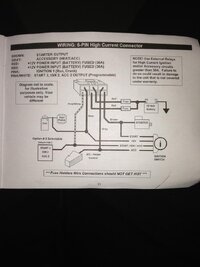
*6 PINS PLUG (ALL CONNECTED TO THE VEHICLE)
GREY(ACC 1) = (C201) D1 ORANGE
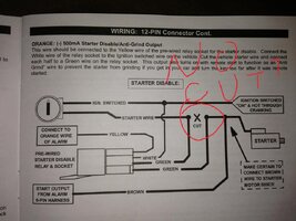
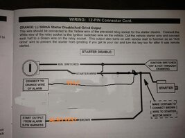
BROWN(STARTER) = (C201) C1 YELLOW ( CUT THE WIRE FOR ANTI GRIND)
BOTH REDS(12V) = (C201) D2 RED (C201) B5 RED&WHITE? ( DO I HAVE TO USE BOTH D2 & B5 OR JUST ONE OF THEM? )
PINK(IGN) = (C201) C6 PINK
PINK&WHITE(SELECTABLE:ST#2/IGN#2/ACC#2) = (C201) C5 WHITE
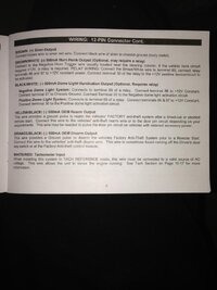
*12 PINS
WHITE&RED(TACH ENGINE MONITOR) = WHITE @ PCM BLUE PLUG#49
BLACK(GND) = MAIN GND
WHITE(-500mA/+10Amps) = ?
RED/BLACK(10 Amps FUSE) = ?
BROWN(SIREN) = SIREN FROM STARTER
BROWN&WHITE = NEEDS A RELAY TO FACTORY HORN?
BLACK&WHITE(DOMELIGHT) = RELAY = ?
GREEN&RED(TRUNK POP RELAY0 = N/A
YELLOW&BLACK(OEM ARM) = NOT NEEDED?
ORANGE&BLACK(OEM DISARM) = NOT NEEDED?
ORANGE(- ARM ) = STARTER KILL RELAY
*YELLOW(86) = GREEN OF 12 PINS
*WHITE(85) = (C201) C6 PINK
*GREEN(30) = (C201) C1 YELLOW (CUT) OTHER SIDE
*GREEN(87) = (C201) C1 YELLOW (CUT) MOTOR SIDE
BLUE&WHITE(PASS DOOR LOCK) = ?
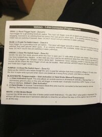
*7 pins
WHITE(+BRAKE SWITCH) = BRAKE PAL ( WHITE WIRE @ FLASHER)
BLK&WHITE(START ACT/HAND BREAK) = ?
PINK(WAIT TO START/CAR JACK) = ?
PURPLE(+DOOR SWITCH) = ?
GREEN(-DOOR SWITCH) = ?
BLUE(-TRUNK SWITCH) = N/A
GRAY(-HOOD SWITCH) = HOOD SWITCH
As you can see most of them are "?" cause I dont know where to connect them or Im not sure., please guide me and correct me for my connections,. thank you and I really appreciate it..View attachment 28807
Hope you guys can help me., I know its easy to bring it to installer and pay $$$.. But for me If I can do it,why not? and to save as well.. ( Everytime I accomplish something by myself,( w/ the help of others. ) It makes me proud and happy.. So what I have is Crime Stopper SP-502 and OMEGA DB-GMDL-BP bypass..
View attachment 28804
And as I understand from MAY03LT connection from blazinlow89 thread, my connections are:
View attachment 28805
(LEFT SIDE)
Status LED
Shock Sensor
* Door Lock Plug (White 3 PinS Plug)
BLUE (UNLOCK (-) ) = ?
RED ( 12V ) FOR RELAYS = ?
GREEN (LOCK (-) ) = ?
*LOW CURRENT PLUG (Blue 4 PinS Plug)
GREEN&WHITE (-) IGN/AUX = ?
VIOLET&WHITE (-) ACC/AUX3 = ?
BLUE&BALACK (-) RUN/AUX2 = ?
BLUE/ORANGE (-) STARTER = ?
*OMEGA DB-GMDLBP
BROWN(NEG GND WHEN RUNNING) = ?
GREEN(LOCK INPUT) = ?
BLUE(UNLOCK INPUT) = ?
VIO&WHTE = ?
VIOLET(DATA OUTPUT) = PURPLE WIRE(OBD2 CONN)
PINK&WHTE(DOOR TRIG OUTPUT) = ?
PINK(DOME LIGHT INPUT) = ?
ORANGE(PANIC INPUT) = ?
RED(12V CONSTANT) = ?
BLACK(CHASIS GND) = GND
(RIGHT SIDE)
*6 PINS PLUG (ALL CONNECTED TO THE VEHICLE)
GREY(ACC 1) = (C201) D1 ORANGE
BROWN(STARTER) = (C201) C1 YELLOW ( CUT THE WIRE FOR ANTI GRIND)
BOTH REDS(12V) = (C201) D2 RED (C201) B5 RED&WHITE? ( DO I HAVE TO USE BOTH D2 & B5 OR JUST ONE OF THEM? )
PINK(IGN) = (C201) C6 PINK
PINK&WHITE(SELECTABLE:ST#2/IGN#2/ACC#2) = (C201) C5 WHITE
*12 PINS
WHITE&RED(TACH ENGINE MONITOR) = WHITE @ PCM BLUE PLUG#49
BLACK(GND) = MAIN GND
WHITE(-500mA/+10Amps) = ?
RED/BLACK(10 Amps FUSE) = ?
BROWN(SIREN) = SIREN FROM STARTER
BROWN&WHITE = NEEDS A RELAY TO FACTORY HORN?
BLACK&WHITE(DOMELIGHT) = RELAY = ?
GREEN&RED(TRUNK POP RELAY0 = N/A
YELLOW&BLACK(OEM ARM) = NOT NEEDED?
ORANGE&BLACK(OEM DISARM) = NOT NEEDED?
ORANGE(- ARM ) = STARTER KILL RELAY
*YELLOW(86) = GREEN OF 12 PINS
*WHITE(85) = (C201) C6 PINK
*GREEN(30) = (C201) C1 YELLOW (CUT) OTHER SIDE
*GREEN(87) = (C201) C1 YELLOW (CUT) MOTOR SIDE
BLUE&WHITE(PASS DOOR LOCK) = ?
*7 pins
WHITE(+BRAKE SWITCH) = BRAKE PAL ( WHITE WIRE @ FLASHER)
BLK&WHITE(START ACT/HAND BREAK) = ?
PINK(WAIT TO START/CAR JACK) = ?
PURPLE(+DOOR SWITCH) = ?
GREEN(-DOOR SWITCH) = ?
BLUE(-TRUNK SWITCH) = N/A
GRAY(-HOOD SWITCH) = HOOD SWITCH
As you can see most of them are "?"
cause I dont know where to connect them or Im not sure., please guide me and correct me for my connections,. thank you and I really appreciate it..View attachment 28807