As with many other Trailblazer/Envoy/etc... owners, most of my stock speakers bit the dust and I needed to replace them. I wanted to do a "Sneaky Pete" install, or a full speaker upgrade that at least looks as stock as possible. I feel like I really achieved that with this installation.
I did not upgrade the head unit strictly out of necessity at this time, as replacing the speakers was the highest priority and my budget did not allow for the HU I wanted. I hope to put in a double-din NAV/Bluetooth HU soon (fingers crossed on a good tax return!).
What I went with:
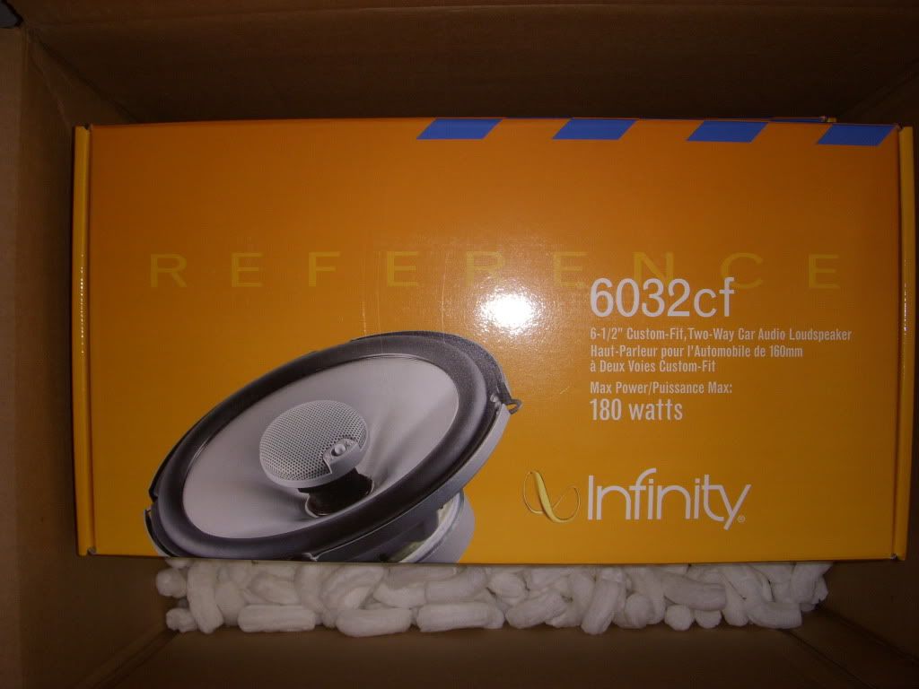
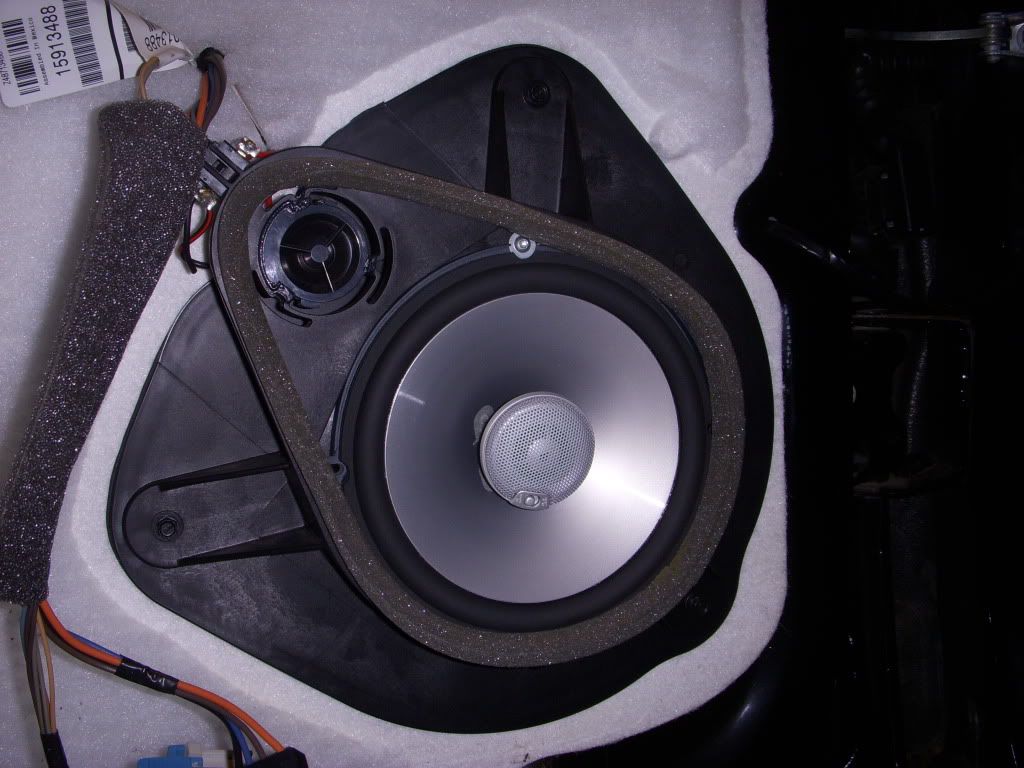
Speakers: (4) Infinity Reference 6032cf 6.5" 2-Way (60 Watts RMS each)
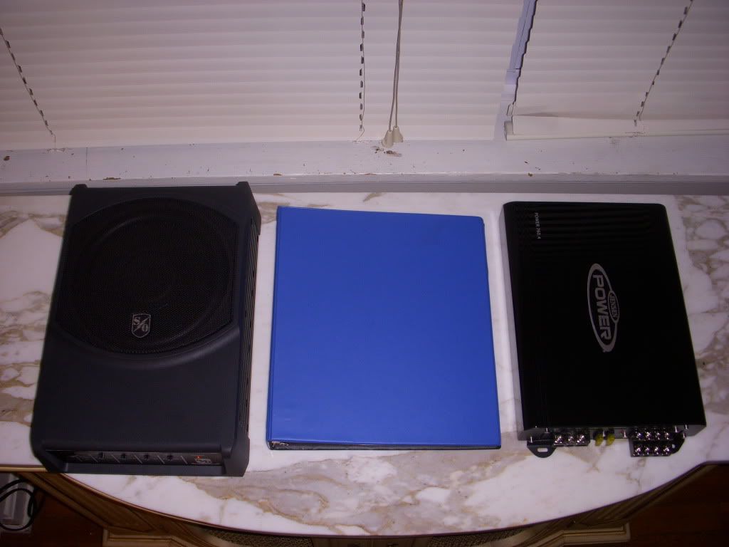
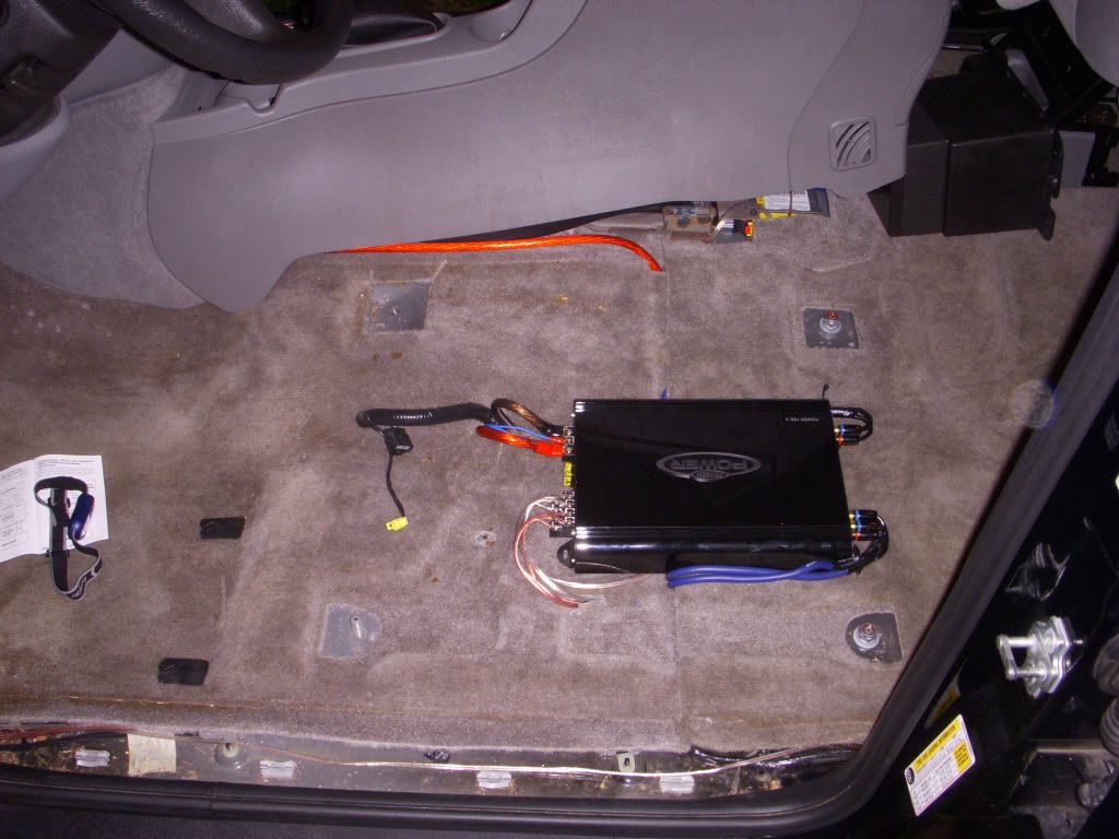
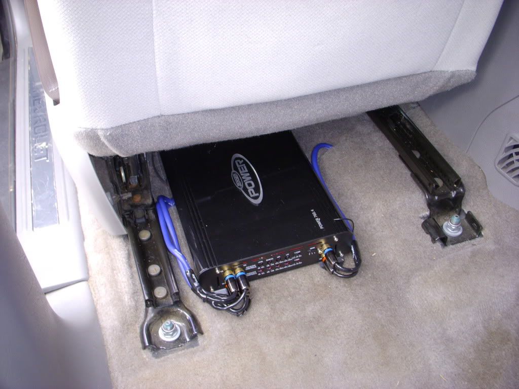
Amplifier: (1) Jensen Power 760.4 4-Channel Amplifier (75 Watts x 4 RMS)
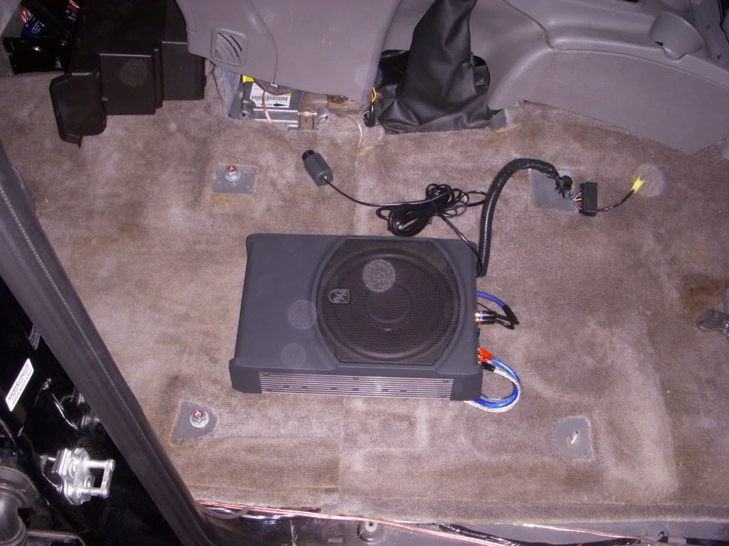
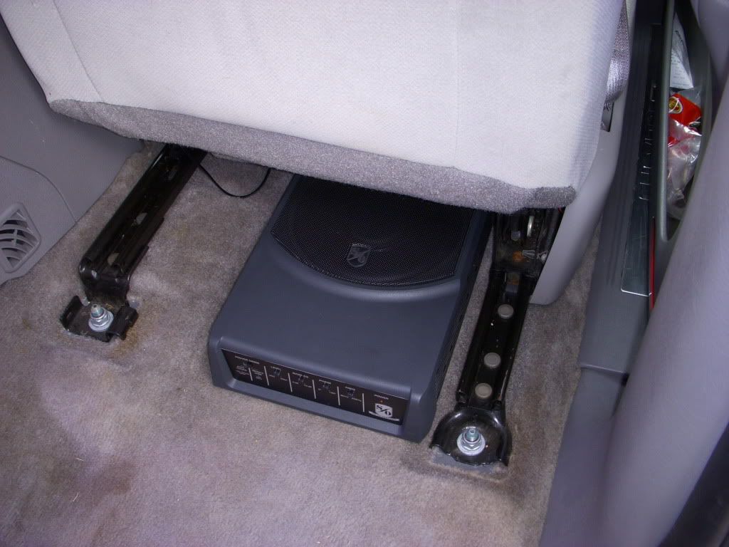
Subwoofer: (1) Sound Ordnance B-8PT Powered Subwoofer (120 Watts RMS)
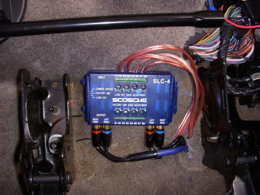
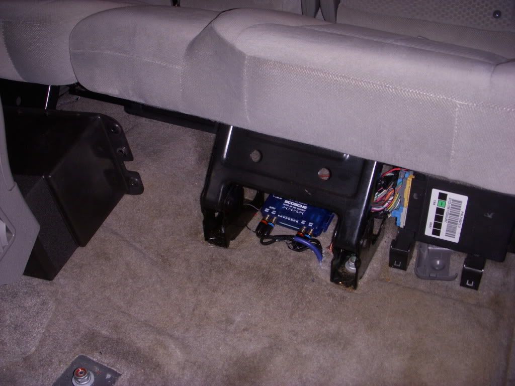
Wiring: (1)Stinger Battery Terminal Adapter (Should be a SHORT adapter for Trailblazer), (1) dbLink PK4Z 4-Gauge Kit (Amp), (1) SCOSCHE EFX-142PA8 8-Gauge Kit (Subwoofer), (1) SCOSCHE SLC-4 Speaker Level Converter (Line Out Converter)
Tools needed for an identical install (especially for you fellow newbies/first timers):
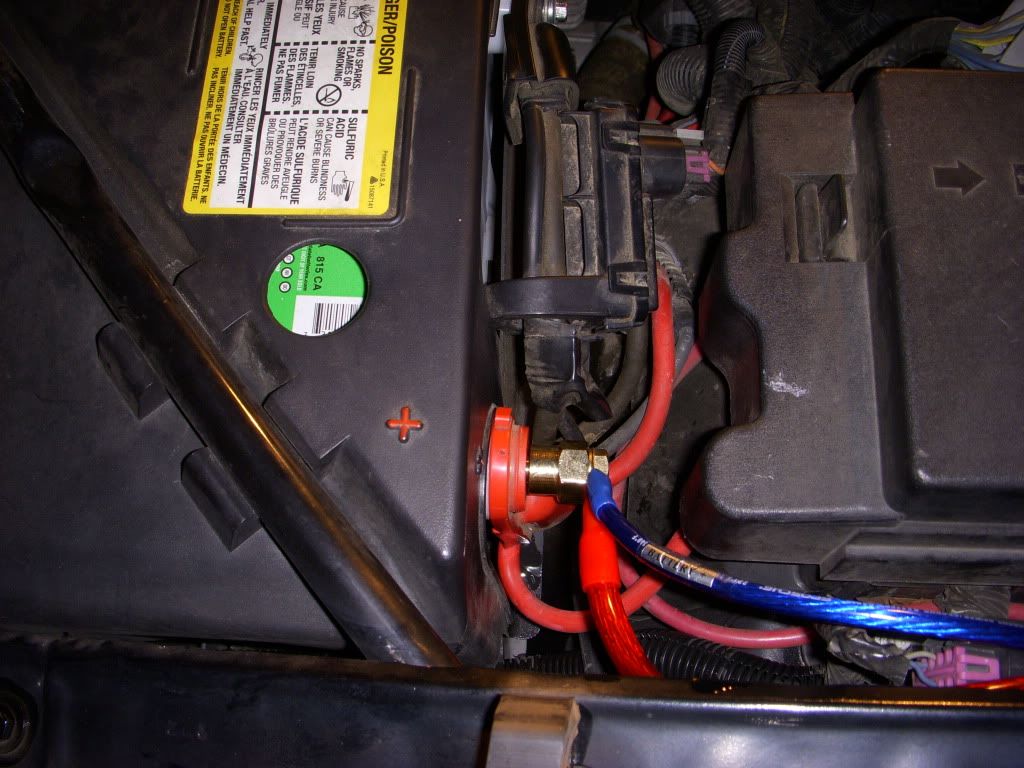
Start by removing the cables from the battery. ALWAYS remove the (-)NEGATIVE (black) cable first. I remove both the NEGATIVE and POSITIVE cables to be safe when working on anything in the electrical system.
Next, remove the seats. This is simpler than I would have thought. On newer models there will be small plastic caps that cover the seat bolts. Use a flat head screwdriver to release the tabs (gently, these will break under pressure) and pull off the covers. Then use a 15mm socket (a deep/long socket will be easier) to loosen the 3 nuts and one bolt (the one closest to the console on each seat will be a bolt).
On my LS model (no power seats) there were two electrical connectors on the front of the seats under the "slide forward/back" back bar on the front. Remove the connectors and pull the seats out.
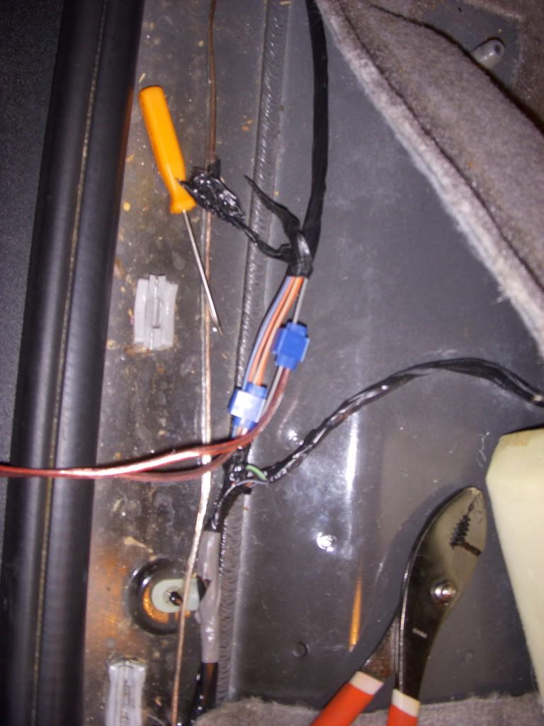
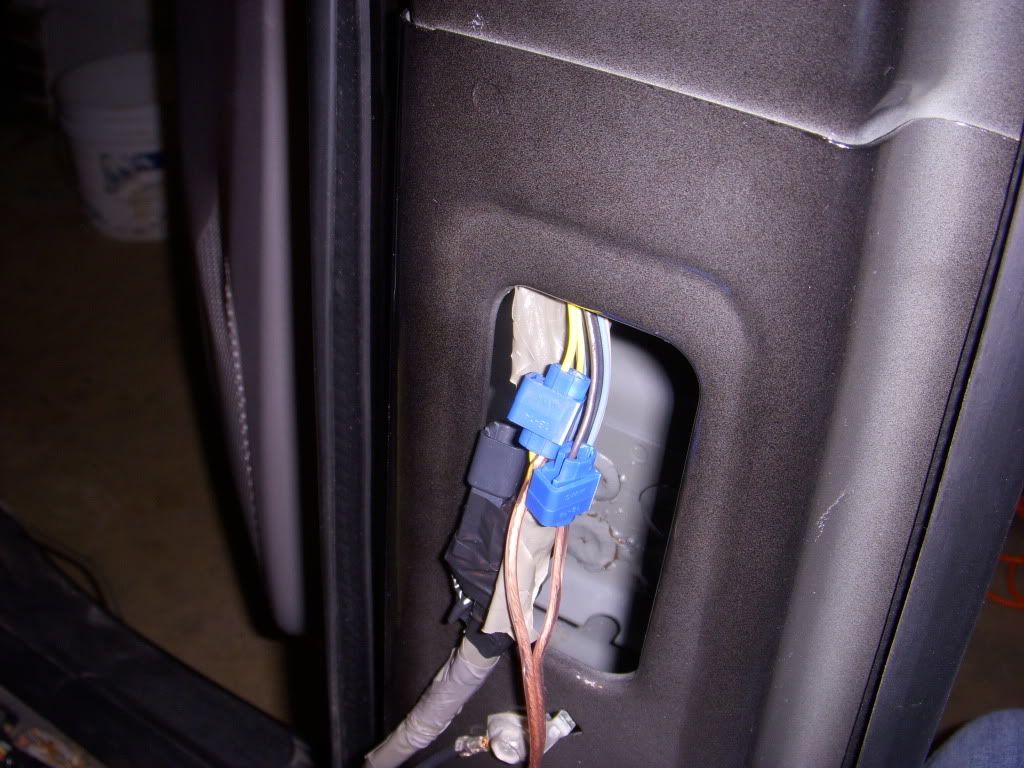
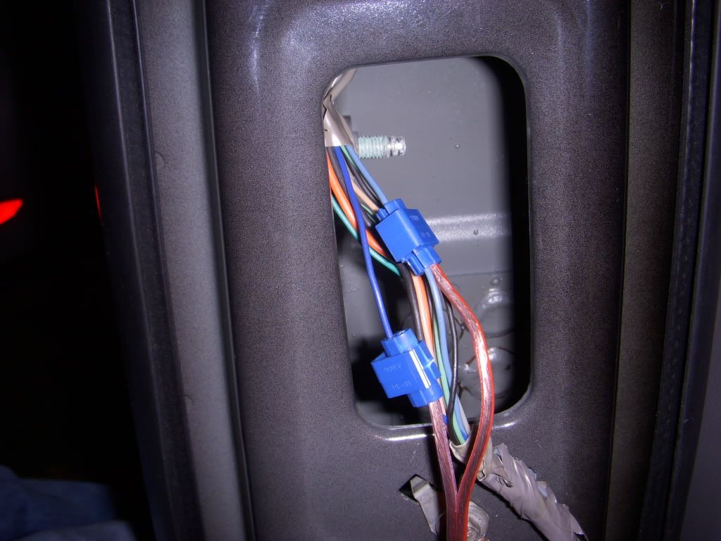
The Kick Panels/Door Sills and B-Pillars are held in by standard automotive clips, and easily removed. Search YouTube or Google for step-by-step, there are many videos out there on this step.
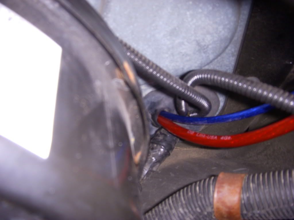
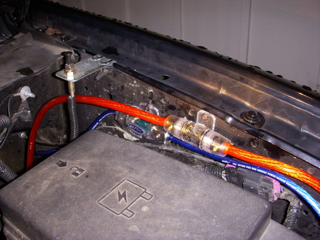
Now run the power wires. Find a suitable location (close enough to the terminal for the pre-cut wires to reach) to mount the fuse blocks on the driver side of the engine compartment. You may want to simply mark these locations first, then screw them in later to ease running the wires through the rubber boot.
NOTE: I happened to already have 2 separate wiring kits, however, it would have likely been easier to just run one 4-Gauge wire through the boot, and then install a distribution block in the cabin.
TIPS:
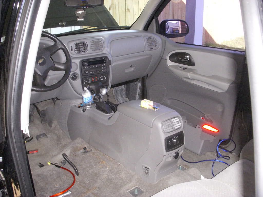
Next, loosen the center console. There are (2) 7mm bolts under the two front rubber cupholders, (4) Phillips head screws under rubber inserts inside of the storage compartment, and (2) more 7mm bolts under the compartment liner. There is also a Torx screw in the front of the shifter you can undo to move the console more freely. I did not completely remove the console, undoing these screws/bolts game me enough freedom to lift/move the console around to feed the wires where they needed to go. There are other posts/videos you can look up online to get more detailed instructions on this step.
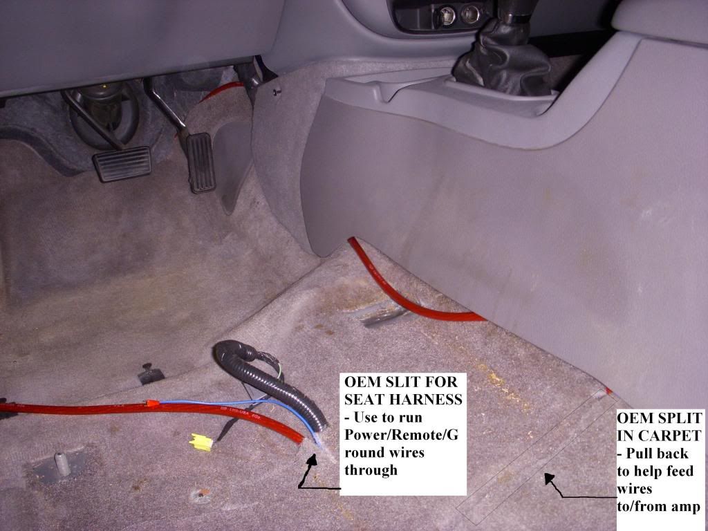
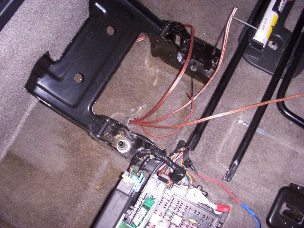
Once I had the power wires inside the cabin, I (after running them 3 different ways and changing my mind 3 different times!) ran them under the carpet behind the pedals and down either side of the center console. At this point it becomes obvious how helpful the "split" carpet pattern GM utilized at the factory can be. The carpet is cut in two sections horizontally in the vehicle. Pull the back portion of the carpet up to help in running the power wires under the carpet, out through the factory slits where the OEM seat harnesses come through the carpet.
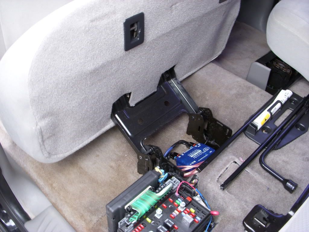
Vehicle cabin with everything removed:
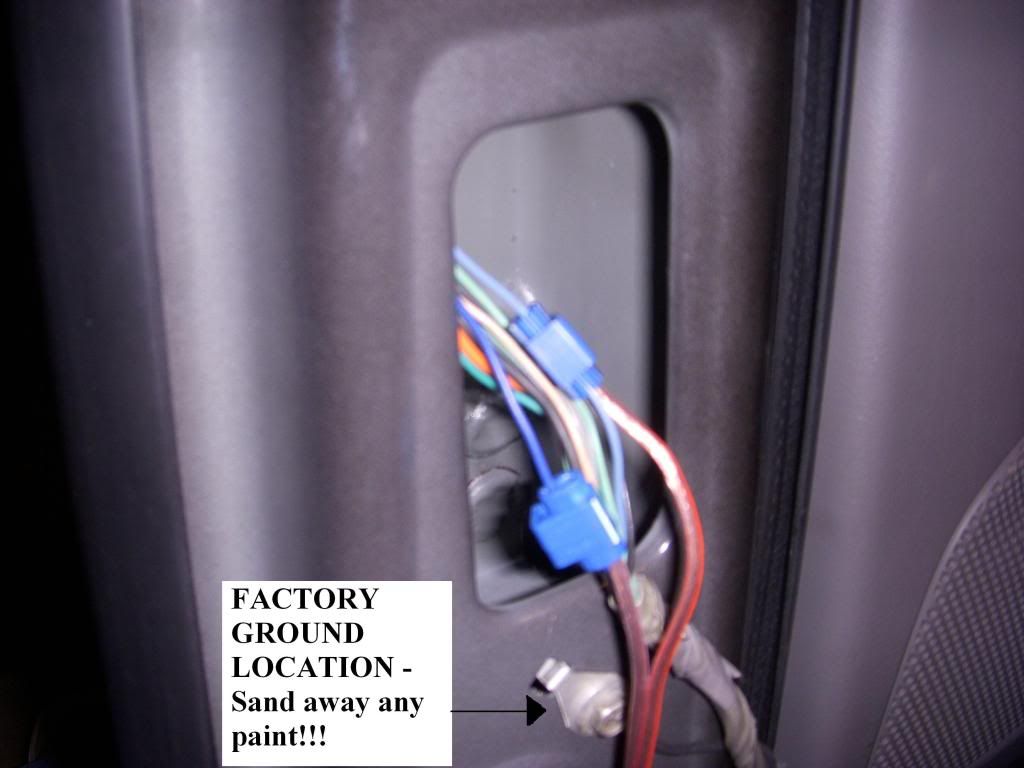
Next, I ran my ground wires for the amp and powered sub. There are many opinions on the best ground location. I had originally planned on grounding to the seat bolts, however, decided against it when I realized the bolts were too large for the terminal connections I had on hand to fit around. Instead, I used existing OEM ground locations on the B-Pillars (not ideal being that these locations are not in direct contact with the frame, but after install I have found I have minimal accelerator "whine" and they seem to be good enough). Be sure to sand away any existing paint and place your ground wires underneath the existing factory ground wires.
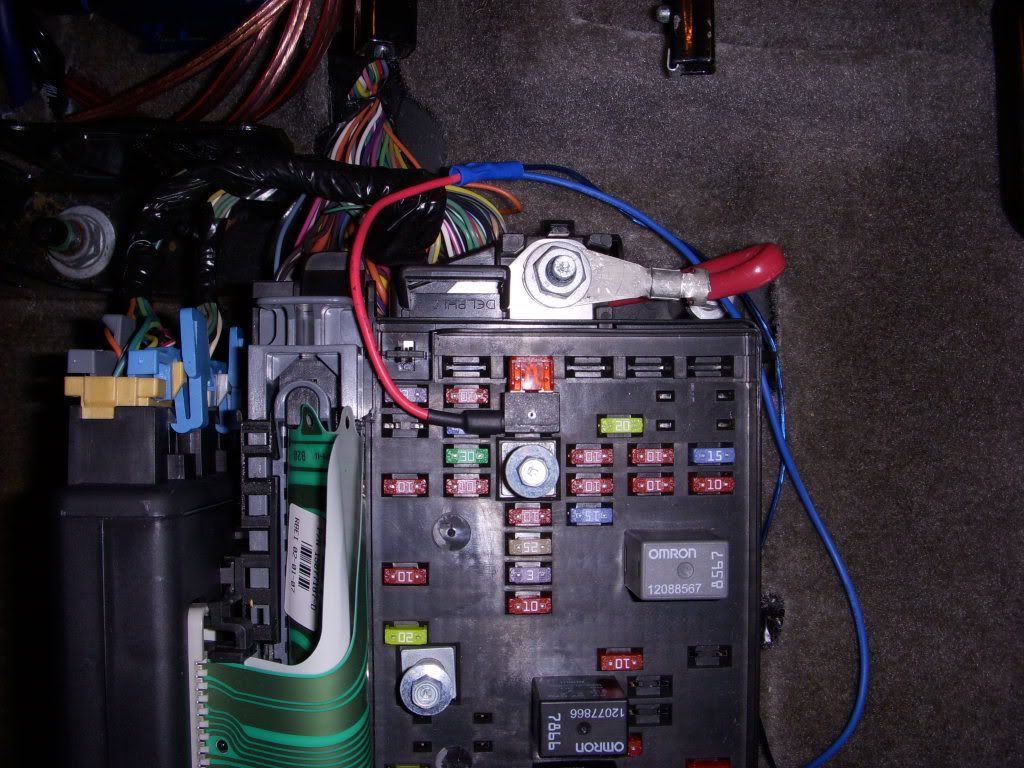
Now, you can run the remote start wires to the fuse box under the rear seat. Replace fuse #47 (10amp) with your "Add-A-Fuse"/"Add-A-Circuit" wire. Twist the ends of your remote wires together and crimp in to the end of your "Add-A-Fuse" wire. This is the first time you might find using a wire hangar helpful to pull wires from one side of the vehicle to the other (straighten the wire hangar and make a small loop at one end, tying the tag end of the passenger side remote wire to the loop, and pull underneath the carpet).
(Continued)...
I did not upgrade the head unit strictly out of necessity at this time, as replacing the speakers was the highest priority and my budget did not allow for the HU I wanted. I hope to put in a double-din NAV/Bluetooth HU soon (fingers crossed on a good tax return!).
What I went with:
Speakers: (4) Infinity Reference 6032cf 6.5" 2-Way (60 Watts RMS each)
Amplifier: (1) Jensen Power 760.4 4-Channel Amplifier (75 Watts x 4 RMS)
Subwoofer: (1) Sound Ordnance B-8PT Powered Subwoofer (120 Watts RMS)
Wiring: (1)Stinger Battery Terminal Adapter (Should be a SHORT adapter for Trailblazer), (1) dbLink PK4Z 4-Gauge Kit (Amp), (1) SCOSCHE EFX-142PA8 8-Gauge Kit (Subwoofer), (1) SCOSCHE SLC-4 Speaker Level Converter (Line Out Converter)
Tools needed for an identical install (especially for you fellow newbies/first timers):
- Metric Socket Set (7mm, 10mm, and *preferably DEEP/LONG* 15mm, with extensions)
- Flat and Phillips Screwdrivers
- Standard TORX Bit Set (Bit T15H, spectfically, IIRC)
- Wire Stripper
- Wire Crimper
- Razor Knife
- Quick Terminal Disconnects OR Soldering Iron/Solder
- Quick Splices
- Add-A-Fuse (OR Add-A-Circuit) for a 10amp mini fuse (for remote turn-on)
Start by removing the cables from the battery. ALWAYS remove the (-)NEGATIVE (black) cable first. I remove both the NEGATIVE and POSITIVE cables to be safe when working on anything in the electrical system.
Next, remove the seats. This is simpler than I would have thought. On newer models there will be small plastic caps that cover the seat bolts. Use a flat head screwdriver to release the tabs (gently, these will break under pressure) and pull off the covers. Then use a 15mm socket (a deep/long socket will be easier) to loosen the 3 nuts and one bolt (the one closest to the console on each seat will be a bolt).
On my LS model (no power seats) there were two electrical connectors on the front of the seats under the "slide forward/back" back bar on the front. Remove the connectors and pull the seats out.
The Kick Panels/Door Sills and B-Pillars are held in by standard automotive clips, and easily removed. Search YouTube or Google for step-by-step, there are many videos out there on this step.
Now run the power wires. Find a suitable location (close enough to the terminal for the pre-cut wires to reach) to mount the fuse blocks on the driver side of the engine compartment. You may want to simply mark these locations first, then screw them in later to ease running the wires through the rubber boot.
NOTE: I happened to already have 2 separate wiring kits, however, it would have likely been easier to just run one 4-Gauge wire through the boot, and then install a distribution block in the cabin.
TIPS:
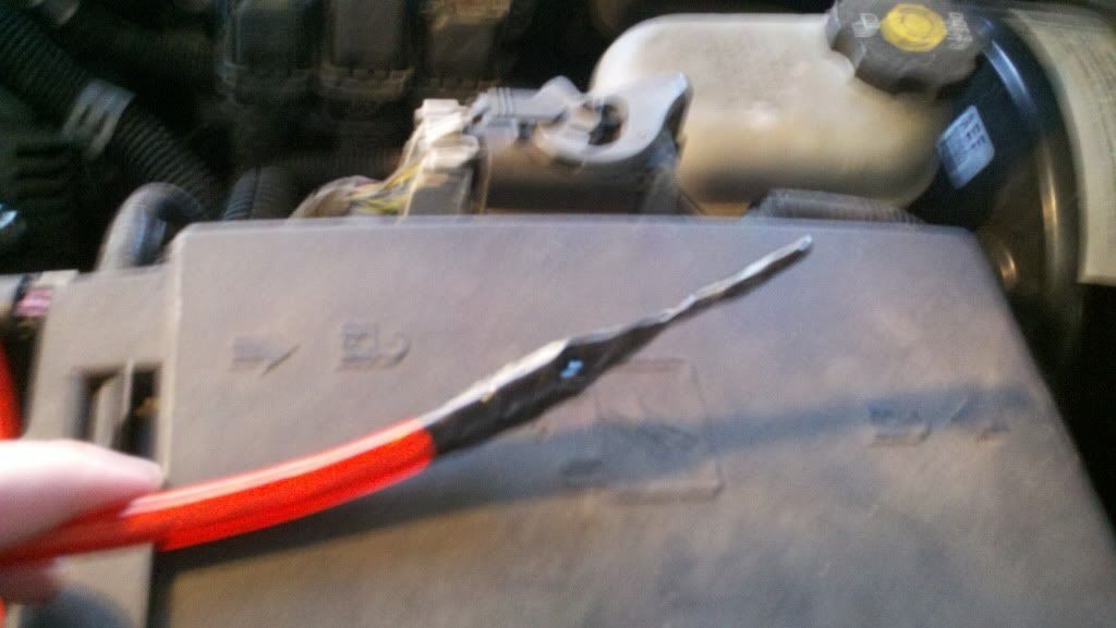
- I used a small knife to cut a "starter hole" in the rubber boot. I felt like this was easier than forcing a screwdriver through, as the screwdriver wanted to pull the whole boot through while pushing on it. I decided to cut above and to the left of the stock wires as I felt that was the easiest place to pull the new wires through.
- AS PICTURED BELOW: I taped two zip ties together and taped over them on the end of the power wire to give myself a tapered point to pull through the boot. This was BY FAR easier than trying to force the blunt end of 4-Gauge wire through.
- A small amount of liquid soap applied to the end of the power wire will do wonders to aid in pulling through the small hole in the boot.
Next, loosen the center console. There are (2) 7mm bolts under the two front rubber cupholders, (4) Phillips head screws under rubber inserts inside of the storage compartment, and (2) more 7mm bolts under the compartment liner. There is also a Torx screw in the front of the shifter you can undo to move the console more freely. I did not completely remove the console, undoing these screws/bolts game me enough freedom to lift/move the console around to feed the wires where they needed to go. There are other posts/videos you can look up online to get more detailed instructions on this step.
Once I had the power wires inside the cabin, I (after running them 3 different ways and changing my mind 3 different times!) ran them under the carpet behind the pedals and down either side of the center console. At this point it becomes obvious how helpful the "split" carpet pattern GM utilized at the factory can be. The carpet is cut in two sections horizontally in the vehicle. Pull the back portion of the carpet up to help in running the power wires under the carpet, out through the factory slits where the OEM seat harnesses come through the carpet.
Vehicle cabin with everything removed:
Next, I ran my ground wires for the amp and powered sub. There are many opinions on the best ground location. I had originally planned on grounding to the seat bolts, however, decided against it when I realized the bolts were too large for the terminal connections I had on hand to fit around. Instead, I used existing OEM ground locations on the B-Pillars (not ideal being that these locations are not in direct contact with the frame, but after install I have found I have minimal accelerator "whine" and they seem to be good enough). Be sure to sand away any existing paint and place your ground wires underneath the existing factory ground wires.
Now, you can run the remote start wires to the fuse box under the rear seat. Replace fuse #47 (10amp) with your "Add-A-Fuse"/"Add-A-Circuit" wire. Twist the ends of your remote wires together and crimp in to the end of your "Add-A-Fuse" wire. This is the first time you might find using a wire hangar helpful to pull wires from one side of the vehicle to the other (straighten the wire hangar and make a small loop at one end, tying the tag end of the passenger side remote wire to the loop, and pull underneath the carpet).
(Continued)...
 Very thorough write up
  I don't know if those with power seats would have enough clearance to mount their amp and power sub there, but good work on that. Nice and clean.


 Haha yeah man that was half the reason I put it there! Reminding me of a certain scene in "Howard Stern: Private Parts"...lol.