This might help too:
Diversity Antenna System
Description and Operation
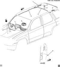
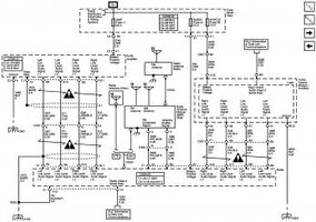
This diversity antenna system is comprised of 3 glass mounted antennas, a radio antenna module, and an FM impedance matching module (Radio Antenna Buffer). The primary AM and FM antennas are an integral part of the right rear quarter glass and are connected to the radio antenna module. The secondary FM antenna is an integral part of the left rear quarter glass and is connected to the FM impedance matching module. The radio antenna module processes the antenna reception signals and phase aligns them to create one strong signal. The FM impedance matching module boosts the secondary antenna signal and transmits it to the radio antenna module.
The following information lists the most probable cause of the concern to the least probable cause followed by the appropriate test for that condition. If the test leads to the replacement of a component, always inspect for a poor connection before proceeding with the replacement. Refer to Testing for Intermittent Conditions and Poor Connections and Connector Repairs in Wiring Systems.
Important: Perform the Antenna System Test and test the antenna coax cable prior to performing any of the following tests. Total resistance from end to end of center conductor should be 0.20 Ω or less.
Poor Reception on Both AM and FM Bands
The radio antenna module is not grounded properly. The module grounding screws should be clean and tight. The antenna module ground is either a chassis ground or a ground strap. Measure the resistance from the antenna module base plate to a good ground. Resistance should be 0.20 Ω or less. Find and correct the condition if the resistance is out of specification.
The antenna enable signal is not present at the radio antenna module. This could be caused by an output failure of the radio or an open/shorted antenna enable signal circuit. In order to test the antenna enable signal circuit, the radio must be ON and tuned to the FM band. Disconnect the radio antenna module. Measure the voltage from the antenna enable signal circuit of the radio antenna module to a good ground. Voltage measured should be near B+. If the specified voltage is measured, test the antenna enable signal circuit for an open or short to ground. Refer to Circuit Testing and Wiring Repairs in Wiring Systems. If no failures were found, replace the radio. Refer to Radio Replacement for service procedure.
The FM composite signal circuit to the radio antenna module is open or shorted to ground. Test the FM composite signal circuit for an open or short to ground. Refer to Circuit Testing and Wiring Repairs in Wiring Systems.
The feed coax at the radio antenna module has been inadvertently swapped with the FM impedance matching module crossover coax. Ensure that the feed coax, marked with a yellow band, is in the correct socket on the radio antenna.
Improper retention of the antenna cable in the floating retainer. Poor or no connection with the radio will result when the radio is installed if the antenna cable is not properly attached in the floating retainer. Inspect the antenna cable for movement in the floating retainer. Replace the antenna cable if movement is found.
Defective radio antenna module. Replace the radio antenna module. Refer to Radio Antenna Module Replacement for service procedure.
Poor Reception on AM Band Only
Defective AM antenna.
Defective radio antenna module. Replace the radio antenna module. Refer to Radio Antenna Module Replacement for service procedure.
The antenna enable signal is not present at the radio antenna module. This could be caused by an output failure of the radio or an open/shorted antenna enable signal circuit. In order to test the antenna enable signal circuit, the radio must be ON and tuned to the FM band. Disconnect the radio antenna module. Measure the voltage from the antenna enable signal circuit of the radio antenna module to a good ground. Voltage measured should be near B+. If the specified voltage is measured, test the antenna enable signal circuit for an open or short to ground. Refer to Circuit Testing and Wiring Repairs in Wiring Systems. If no failures were found, replace the radio. Refer to Radio Replacement for service procedure.
Poor Reception on FM Band Only
Defective primary or secondary FM antenna
The antenna enable signal is not present at the radio antenna module. This could be caused by an output failure of the radio or an open/shorted antenna enable signal circuit. In order to test the antenna enable signal circuit, the radio must be ON and tuned to the FM band. Disconnect the radio antenna module. Measure the voltage from the antenna enable signal circuit of the radio antenna module to a good ground. Voltage measured should be near B+. If the specified voltage is measured, test the antenna enable signal circuit for an open or short to ground. Refer to Circuit Testing and Wiring Repairs in Wiring Systems. If no failures were found, replace the radio. Refer to Radio Replacement for service procedure.
Defective radio antenna buffer. Replace the radio antenna buffer. Refer to Radio Control Module Replacement for service procedure.
Defective radio antenna module. Replace the radio antenna module. Refer to Radio Antenna Module Replacement for service procedure.


