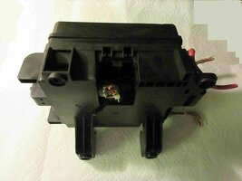
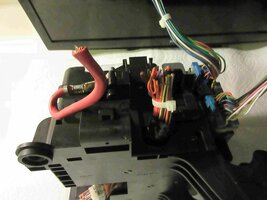
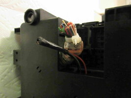
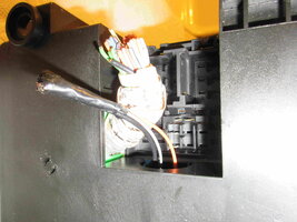
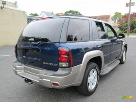
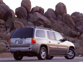
Looking For Body Module Wiring Detail

Jkb242

Original poster
Member
May 19, 2019
250
CLT
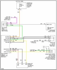
I have the wiring diagrams provided by Mooseman which are invaluable. The particular circuit I am looking for from the BCM is the backup lamp feed. From the particular diagram in the set, “External lamps/backup” I see the two light green wires feeding both backup lamps. The question is in which connector are these wires located at the BCM.. Light green is also a data line connection at the BCM. I understand I could probe each of the light green wires for 12v when in reverse but was hoping to avoid that or removing the rear light lenses to access and confirm that circuit. My driveway is a 10 degree slope and taking it out of park isn’t safe since I’m working alone.

Identifying which connector at the BCM for these wires would be very helpful.

Much thanks!
 

mrrsm

Lifetime VIP Donor
Supporting Donor
Member
Oct 22, 2015
8,087
Tampa Bay Area
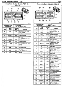
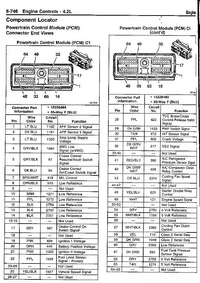
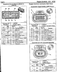
Perhaps among these three Class 2 Network Diagrams... and ... Be VERY Cautious whenever applying 12 Volts DC anywhere into the BCM Circuitry designed to either carry only 5 Volts DC as Reference Voltage or the typical 0 -7 Volts DC present on the Single Wire Class 2 Network communication lines and connections:

TBCLASS2NETWORK2.jpgTBCLASS2NETWORK.jpgTRAILBLAZERBCMDIAGRAM.jpeg

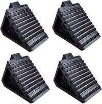
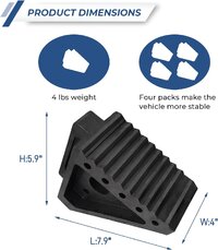
Also... Having a Full Set of Large Rubber Wheel Chocks for situations like your own is always helpful ...especially when having to work SOLO:


RUBBERWHEELCHOCKS.jpg

71Q+7z0x+QS._AC_SL1500_.jpg61iHCU20YcL._AC_SL1500_.jpg81OAFGMu3LL._AC_SL1500_.jpg71i7tE8ok9L._AC_SL1500_.jpg81R2c5BtxLL._AC_SL1500_.jpg81WrYpsegiL._AC_SL1500_.jpg
 
Last edited:
  • Like
Reactions: Mooseman

Jkb242

Original poster
Member
May 19, 2019
250
CLT
Perhaps among these three Class 2 Network Diagrams... and ... Be VERY Cautious whenever applying 12 Volts DC anywhere into the BCM Circuitry designed to either carry only 5 Volts DC as Reference Voltage or the typical 0 -7 Volts DC present on the Single Wire Class 2 Network communication lines and connections:

View attachment 113054View attachment 113055View attachment 113056

Also... Having a Full Set of Large Rubber Wheel Chocks for situations like your own is always helpful ...especially when having to work SOLO:


View attachment 113063

View attachment 113057View attachment 113058View attachment 113059View attachment 113060View attachment 113061View attachment 113062
Thanks for your reply. I am aware of the numerous data connection at the BCM. That’s why I was requesting some information showing the specific connector where the BU lights are contained. A photograph or pictorial diagram showing this connector is all I’m requesting. Again, per the wiring diagram, there are two Lt green leads which connect to the two BU lights.

Can you provide this? I would very much appreciate.
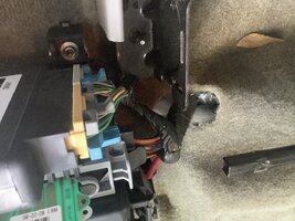
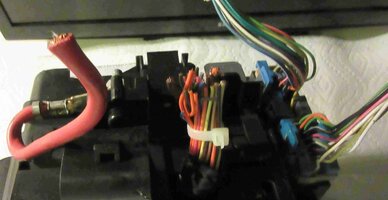
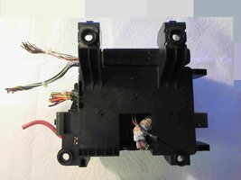
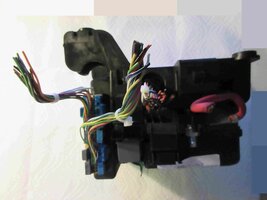
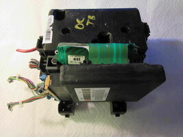
BCM picture attached.

Much thanks!
 

Attachments

  • IMG_0541.jpeg
    IMG_0541.jpeg
    754.3 KB · Views: 7

mrrsm

Lifetime VIP Donor
Supporting Donor
Member
Oct 22, 2015
8,087
Tampa Bay Area
Following on with a more elaborate Video of the Removal of the BCM and its Three Connectors along with the entire Rear Fuse Box.... is there any chance that you can take some images (Front & Back of the particular connector and its Color and Orientation to the BCM interfaces?


The most common and familiar diagrams and images available on line are usually just for the Under-hood 4.2L LL8 ...so since your Vehicle sports the 5.3L V8... perhaps you could memorialize the Rear Fuse Block (and the BCM Connectors) with some Pics (Under The Plastic Fuse Identification Cover showing the Fuse Layout) ...and... All Three BCM Connectors and their Part Numbers... and that might prove useful in running their Wire Pin-Outs and Harnesses to Ground. Also, separating and identifying the Dual Color Wiring with close up images at the connectors might also get them better identified for this research.

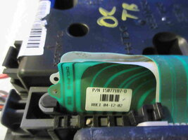
The other issue is that the Rear Tail Lights for the Trailblazers and Envoys is actually a Circuit Board Controller where the Bulbs plug in and peeling the Harness Tape to get a closer look at THEIR Dual Color Coded Wires at the Back Up Light to get images might also prove helpful. This Diagnostic comes courtesy @MAY03LT...Take Note that back then, he was working directly off of the the Tail Light Wiring Diagrams:


One of our more astute members with "All Things Electrical and Electronic" on the GMT360s is @TJBaker57 and sending him a PM is also a wise action to take in getting the information you need.

You would think that having the BCM Devices, Fuse Box Layouts, Circuit Numbers, Wire Color Formats and Harness Diagram Layouts would be MUCH easier to run down in the 21st Century on ALL Vehicles ...but apparently not...because ALL Auto Manufacturers are always so deliberately obtuse.

As a Related Aside... Concerning Probing the Under Fuse Blocks (or in your case The BCM Blocks)...


HERE is another possibility that involves a Chevrolet Truck with Harness, Fuse Box & BCM Issues solved by Eric "O" from SMA (South Main Auto) relating to the RPO Codes vs. the ACTUAL Wiring Harnessing being WRONG... so keep that possibility in the back of your mind:


And just for the On Topic (Diagnostics) issues of having "No Reverse Lights...":

 
Last edited:

Jkb242

Original poster
Member
May 19, 2019
250
CLT
Following on with a more elaborate Video of the Removal of the BCM and its Three Connectors along with the entire Rear Fuse Box.... is there any chance that you can take some images (Front & Back of the particular connector and its Color and Orientation to the BCM interfaces?


The most common and familiar diagrams and images available on line are usually just for the Under-hood 4.2L LL8 ...so since your Vehicle sports the 5.3L V8... perhaps you could memorialize the Rear Fuse Block (and the BCM Connectors) with some Pics (Under The Plastic Fuse Identification Cover showing the Fuse Layout) ...and... All Three BCM Connectors and their Part Numbers... and that might prove useful in running their Wire Pin-Outs and Harnesses to Ground. Also, separating and identifying the Dual Color Wiring with close up images at the connectors might also get them better identified for this research.

The other issue is that the Rear Tail Lights for the Trailblazers and Envoys is actually a Circuit Board Controller where the Bulbs plug in and peeling the Harness Tape to get a closer look at THEIR Dual Color Coded Wires at the Back Up Light to get images might also prove helpful. This Diagnostic comes courtesy @MAY03LT...Take Note that back then, he was working directly off of the the Tail Light Wiring Diagrams:


One of our more astute members with "All Things Electrical and Electronic" on the GMT360s is @TJBaker57 and sending him a PM is also a wise action to take in getting the information you need.

You would think that having the BCM Devices, Fuse Box Layouts, Circuit Numbers, Wire Color Formats and Harness Diagram Layouts would be MUCH easier to run down in the 21st Century on ALL Vehicles ...but apparently not...because ALL Auto Manufacturers are always so deliberately obtuse.

As a Related Aside... Concerning Probing the Under Fuse Blocks (or in your case The BCM Blocks)...


HERE is another possibility that involves a Chevrolet Truck with Harness, Fuse Box & BCM Issues solved by Eric "O" from SMA (South Main Auto) relating to the RPO Codes vs. the ACTUAL Wiring Harnessing being WRONG... so keep that possibility in the back of your mind:


And just for the On Topic (Diagnostics) issues of having "No Reverse Lights...":

Thanks again for your input. The video outlining the removal of the BCM was informative. I had not considered the necessity to remove it nor is it clear that it’s necessary for my specific need. I am hoping the BU light feeds (Lt green wires) are located in one of the top connectors to the BCM. According to the wiring diagram, the 12v BU light feed is only fused at the main fuse block in the front of the vehicle. The feeds from the BCM to the BU lights isn’t fused again so it would appear they are not routed to the bottom harnesses shown in the video. As you requested, I will take another picture showing of the top connectors where it “appears” the two Lt green wires feeding the BU lights are located, which is my hope.

As side note regarding the circuit board of each rear light assembly, there was a failure previously in the left side brake lamp. These circuit boards can be removed and repaired. That is how I fixed the defective one in my case saving me the cost of replacing it, approx $90 for the used part from the GM Parts supplier many here have used. If there is any interest in this I would be happy to offer to anyone else if desired.

Hopefully TJBAKER57 (indeed he’s a valuable source) can join this effort. I will post these pictures in a separate response today. Much thanks
 
  • Like
Reactions: mrrsm

budwich

Member
Jun 16, 2013
2,139
kanata
not sure if the info that I have is correct (gmc 2006 envoy) for your specific vehicle but the back up lamp feed passes thru the rear fuse block (not fused though) on C4 B12 (in) and out on C1 A4. It leaves the BCM on C3 B12. According to my info, the wiring at the BCM is FW (ribbon) ... the L-GN doesn't appear until after it leaves the rear fuse block.

Again, not sure how accurate that info is from the SM that I have.

Further: connector C1 is GY, C2 is TN and C3 is BK at the BCM

One question: what are you trying to do?
 
Last edited:

mrrsm

Lifetime VIP Donor
Supporting Donor
Member
Oct 22, 2015
8,087
Tampa Bay Area
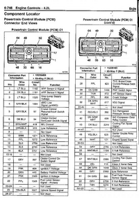
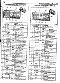
If you decide to perform a Continuity Check from the PCM to the BU Light Fuse in the Under-hood Fuse Box... Here are the PCM Pin-Outs Images for reference by Circuit Number, etc

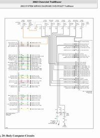
Also...I did manage to find yet another Schematic that does refer to the External Light Circuitry:

2002BODYCOMPUTERCIRCUITS.jpg

upload_2017-4-25_20-33-51.pngupload_2017-4-25_20-34-21.pngupload_2017-4-25_20-34-43.pngupload_2017-4-25_20-37-25.png2004trailblazerpcm4-jpg.73337.jpeg
 
Last edited:

Jkb242

Original poster
Member
May 19, 2019
250
CLT
not sure if the info that I have is correct (gmc 2006 envoy) for your specific vehicle but the back up lamp feed passes thru the rear fuse block (not fused though) on C4 B12 (in) and out on C1 A4. It leaves the BCM on C3 B12. According to my info, the wiring at the BCM is FW (ribbon) ... the L-GN doesn't appear until after it leaves the rear fuse block.

Again, not sure how accurate that info is from the SM that I have.

Further: connector C1 is GY, C2 is TN and C3 is BK at the BCM

One question: what are you trying to do?
This effort was begun to address the installation of a rear backup camera for this vehicle. I have the option to switch in the camera and turn on the dash mounted monitor when backing. It’s working now but activated by a manually operated switch.

The attachment you provided is vey helpful and confirms what I have taken from the wiring diagram originally referenced in the OP. The feed from the BCM B12 ultimately connects to both BU light feeds. That’s all I need to complete this objective. I do not understand where I can access B12. I do not need the individual feeds to each BU LIGHT (Light green wires). The common supply feed at B12 is fine. Can you tell me which connector on the BCM houses B12 if in fact it’s in one of the two mass BCM connectors? If it passes through the fuse block as you state what color is it and which harnes is it in?

Thanks very much.
 

budwich

Member
Jun 16, 2013
2,139
kanata
Can you tell me which connector on the BCM houses B12
I think that information is already provided in my post.... C3 which is BK in color.... again assuming that info lines up with you vehicle as I can't guaranty that as it is "generic" to the year model that I have indicated.
 

mrrsm

Lifetime VIP Donor
Supporting Donor
Member
Oct 22, 2015
8,087
Tampa Bay Area
Sorry that this took so long to dope out... but below is a Complete Pin-Out List for All Three BCM Connectors (...with a prepared PDF if the Mods want to add the data to the FAQ):

XLARGECLOSEUPOFBCMCONNECTORS.jpg

The Layouts Follow THIS Format:


Body Control Module (BCM) C#
Pin Wire Color Circuit No. Function

------------------------------------------------------------------------------------------------------

Body Control Module (BCM) C1


Connector Part Information
OEM: 12110088
Service: 15306210
Description: 24-Way F Micro-Pack 100 Series (GY)
Terminal Part Information
Pins: A2, A3, A4, A5, A6, A12, B1, B2, B3, B4, B5, B6, B7, B8, B9, B10, B11, B12
Terminal/Tray: 12146447/3
Core/Insulation Crimp: E/C
Release Tool/Test Probe: 12031876-1/J-35616-6 (BN)

Body Control Module (BCM) C1
Pin Wire Color Circuit No. Function


A1---- Not Used
A2 WH 2282 Headlamp Washer Relay Control (CE4)
A3 OG 1140 Battery Positive Voltage
A4 BK/WH 1969 Headlamp High Beam Relay Control
A5 PK/WH 1970 Headlamp Low Beam Relay Control
A6 PK 5363 Inclination Sensor Low Reference (BAE)
A7-A11 ---- Not Used
A12 WH 278 Ambient Light Sensor Signal
B1 L-GN 1037 Class 2 Serial Data
B2 BK 279 Ambient Light Sensor Low Reference
B3 L-GN 2270 Rear Window Washer Relay Control
B4 GY/BK 2226 Instrument Panel Lamps Dimmer Switch Low Reference
B5 GY 705 5-Volt Reference
B6 WH 2283 12-Volt Reference
B7 OG/BK 2090 Courtesy Lamps Supply Voltage
B8 L-GN 1011 Remote Radio Control Signal (STW)
B9 GY391 Rear Window Wiper Switch Signal
B10 YE 1836 Security System Sensor Signal
B11 GY 2521 Right Sunload Sensor Signal (CJ2)
B12 L-BU/BK 2519 Left Sunload Sensor Signal (CJ2)

Body Control Module (BCM) C2

Connector Part Information
OEM: 12110112
Service: 12110112
Description: 32-Way F Micro-Pack 100 Series (TN)
Terminal Part Information
Pins: E3, E4, E5, E6, E7, E8, E9, E11, E12, E14, F3, F4, F5, F6, F7, F8, F9, F10, F11, F13
Terminal/Tray: 12146447/3
Core/Insulation Crimp: E/C
Release Tool/Test Probe: 12031876-1/J-35616-6 (BN)

Body Control Module (BCM) C2
Pin Wire Color Circuit No. Function


E1-E2 ---- Not Used
E3 L-GN 80 Key In Ignition Switch Signal
E4 YE 307 Headlamp Switch Flash to Pass Signal
E5 GY/BK 308 Park Lamp Switch On Signal
E6 PK/BK 109 Hood Ajar Switch Signal (UA2)
E7 PK 1348 Headlamp On Indicator Control
E8 BK 1835 Security System Sensor Low Reference
E9 RD/WH 812 12-Volt Reference
E10 ---- Not Used
E11 D-GN/WH 1317 Fog Lamp Relay and Indicator Control (T96)
E12 BK 28 Horn Relay Control
E13 ---- Not Used
E14 TN 5463 Daytime Running Lamp Override Indicator
E15-E16 ---- Not Used
F1-F2 ---- Not Used
F3 D-GN 113 Windshield Wiper Switch Signal 2
F4 D-BU/WH 1495 Courtesy Lamps On Signal
F5 BN/WH 1871 Headlamp Washer Switch Signal (CE4)
F6 OG 192 Front Fog Lamps Switch Signal (T96)
F7 L-BU 187 Rear Fog Lamps Switch Signal (T79)
F8 L-GN 5462 DRL Defeat Switch Signal
F9 WH 103 Headlamp Switch Headlamps On Signal
F10 L-GN 11 Headlamp High Beam Supply Voltage
F11 PU 328 Interior Lamp Defeat Switch Signal
F12 ---- Not Used
F13 PK 5068 Intrusion Sensor Switch Disable Signal (BAE)
F14-F16 ---- Not Used

Body Control Module (BCM) C3

Connector Part Information
OEM: 15354796
Service: See Catalog
Description: 40-Way F Printed Circuit Flexible (GY)
Terminal Part Information
Pins: A1, A2, A3, A4, A5, A6, A8, A11, A12, A13, A14, A15, A16, A18, A19, A20, B1, B2, B3, B4, B5, B6, B7, B8, B9, B11, B12, B13, B14, B15, B17, B18, B19, B20
Terminal/Tray: See Terminal Repair Kit
Core/Insulation Crimp: See Terminal Repair Kit
Release Tool/Test Probe: See Terminal Repair Kit

Body Control Module (BCM) C3
Pin Wire Color Circuit No. Function


A1 -- 2140 Battery Positive Voltage
A2 – 2140 Battery Positive Voltage
A3 – 748 Right Rear Door Ajar Switch Signal
A4 – 1134 Park Brake Switch Signal
A5 – 195 Door Lock Control
A6 – 2265 Power Window Lockout Left Rear Control
A7 ---- Not Used
A8 – 747 Left Rear Door Ajar Switch Signal
A9- A10 ---- Not Used
A11 – 1350 Ground
A12 – 1353 RAP Supply Voltage
A13 – 194 Door Unlock Control
A14 – 1080 Park Lamp Relay Control
A15 – 5168 Power Sounder Enable Signal (BAE)
A16 – 5204 Intrusion Sensor Data Signal (BAE)
A17 ---- Not Used
A18 – 992 Ignition 0 Voltage
A19 – 39 Ignition 1 Voltage
A20 – 541 Ignition 3 Voltage
B1 – 230 Instrument Panel Lamps Dimming Control
B2 – 230 Instrument Panel Lamps Dimming Control
B3 – 690 Courtesy Lamp Supply Voltage
B4 – 2240 Battery Positive Voltage
B5 – 1186 Power Window Switch Right Rear Up Signal
B6 – 2266 Power Window Lockout Right Rear Control
B7 – 1188 Power Window Switch Right Rear Down Signal
B8 – 1185 Power Window Switch Left Rear Up Signal
B9 – 1187 Power Window Switch Left Rear Down Signal
B10 ---- Not Used
B11 – 1350 Ground
B12 – 24 Backup Lamp Supply Voltage
B13 – 4440 Battery Positive Voltage
B14 – 1382 LED Dimming Signal
B15 – 543 Accessory Voltage
B16 ---- Not Used
B17 – 4040 Battery Positive Voltage
B18 – 1732 Courtesy Lamps Supply Voltage
B19 – 1977 Rear Fog Lamp Relay and Indicator Control
B20 – 5362 Incline Sensor Signal (BAE)


Additional BMC Layout Images:

45145449604_bece739fc3_c.jpg45820349722_24b2c5b415_c.jpg45145449974_84c8d78dd9_c.jpg45820349862_7216d19ae7_c.jpg45145449864_6a6d2bd9c0_c.jpg45145449344_cd0e84316f_c.jpg45820349772_b21ee904bc_c.jpg45820349612_37ea025196_c.jpg45145449224_f3b3a1e695_c.jpg45145449694_6aa90e05da_c.jpg45820349542_a66726828f_c.jpg45145449094_6ca16021a5_c.jpg45820349472_4d94c25cf9_c.jpg45145448914_8cc526e5d3_c.jpg


Prepared by @mrrsm for www.gmtnation.com on 05/29/2024
 

Attachments

  • BCMALLPINOUTDATA.pdf
    33 KB · Views: 3
Last edited:
  • Like
Reactions: azswiss

Jkb242

Original poster
Member
May 19, 2019
250
CLT
Sorry that this took so long to dope out... but below is a Complete Pin-Out List for All Three BCM Connectors (...with a prepared PDF if the Mods want to add the data to the FAQ):

View attachment 113083

The Layouts Follow THIS Format:


Body Control Module (BCM) C#
Pin Wire Color Circuit No. Function

------------------------------------------------------------------------------------------------------

Body Control Module (BCM) C1


Connector Part Information
OEM: 12110088
Service: 15306210
Description: 24-Way F Micro-Pack 100 Series (GY)
Terminal Part Information
Pins: A2, A3, A4, A5, A6, A12, B1, B2, B3, B4, B5, B6, B7, B8, B9, B10, B11, B12
Terminal/Tray: 12146447/3
Core/Insulation Crimp: E/C
Release Tool/Test Probe: 12031876-1/J-35616-6 (BN)

Body Control Module (BCM) C1
Pin Wire Color Circuit No. Function


A1---- Not Used
A2 WH 2282 Headlamp Washer Relay Control (CE4)
A3 OG 1140 Battery Positive Voltage
A4 BK/WH 1969 Headlamp High Beam Relay Control
A5 PK/WH 1970 Headlamp Low Beam Relay Control
A6 PK 5363 Inclination Sensor Low Reference (BAE)
A7-A11 ---- Not Used
A12 WH 278 Ambient Light Sensor Signal
B1 L-GN 1037 Class 2 Serial Data
B2 BK 279 Ambient Light Sensor Low Reference
B3 L-GN 2270 Rear Window Washer Relay Control
B4 GY/BK 2226 Instrument Panel Lamps Dimmer Switch Low Reference
B5 GY 705 5-Volt Reference
B6 WH 2283 12-Volt Reference
B7 OG/BK 2090 Courtesy Lamps Supply Voltage
B8 L-GN 1011 Remote Radio Control Signal (STW)
B9 GY391 Rear Window Wiper Switch Signal
B10 YE 1836 Security System Sensor Signal
B11 GY 2521 Right Sunload Sensor Signal (CJ2)
B12 L-BU/BK 2519 Left Sunload Sensor Signal (CJ2)

Body Control Module (BCM) C2

Connector Part Information
OEM: 12110112
Service: 12110112
Description: 32-Way F Micro-Pack 100 Series (TN)
Terminal Part Information
Pins: E3, E4, E5, E6, E7, E8, E9, E11, E12, E14, F3, F4, F5, F6, F7, F8, F9, F10, F11, F13
Terminal/Tray: 12146447/3
Core/Insulation Crimp: E/C
Release Tool/Test Probe: 12031876-1/J-35616-6 (BN)

Body Control Module (BCM) C2
Pin Wire Color Circuit No. Function


E1-E2 ---- Not Used
E3 L-GN 80 Key In Ignition Switch Signal
E4 YE 307 Headlamp Switch Flash to Pass Signal
E5 GY/BK 308 Park Lamp Switch On Signal
E6 PK/BK 109 Hood Ajar Switch Signal (UA2)
E7 PK 1348 Headlamp On Indicator Control
E8 BK 1835 Security System Sensor Low Reference
E9 RD/WH 812 12-Volt Reference
E10 ---- Not Used
E11 D-GN/WH 1317 Fog Lamp Relay and Indicator Control (T96)
E12 BK 28 Horn Relay Control
E13 ---- Not Used
E14 TN 5463 Daytime Running Lamp Override Indicator
E15-E16 ---- Not Used
F1-F2 ---- Not Used
F3 D-GN 113 Windshield Wiper Switch Signal 2
F4 D-BU/WH 1495 Courtesy Lamps On Signal
F5 BN/WH 1871 Headlamp Washer Switch Signal (CE4)
F6 OG 192 Front Fog Lamps Switch Signal (T96)
F7 L-BU 187 Rear Fog Lamps Switch Signal (T79)
F8 L-GN 5462 DRL Defeat Switch Signal
F9 WH 103 Headlamp Switch Headlamps On Signal
F10 L-GN 11 Headlamp High Beam Supply Voltage
F11 PU 328 Interior Lamp Defeat Switch Signal
F12 ---- Not Used
F13 PK 5068 Intrusion Sensor Switch Disable Signal (BAE)
F14-F16 ---- Not Used

Body Control Module (BCM) C3

Connector Part Information
OEM: 15354796
Service: See Catalog
Description: 40-Way F Printed Circuit Flexible (GY)
Terminal Part Information
Pins: A1, A2, A3, A4, A5, A6, A8, A11, A12, A13, A14, A15, A16, A18, A19, A20, B1, B2, B3, B4, B5, B6, B7, B8, B9, B11, B12, B13, B14, B15, B17, B18, B19, B20
Terminal/Tray: See Terminal Repair Kit
Core/Insulation Crimp: See Terminal Repair Kit
Release Tool/Test Probe: See Terminal Repair Kit

Body Control Module (BCM) C3
Pin Wire Color Circuit No. Function


A1 -- 2140 Battery Positive Voltage
A2 – 2140 Battery Positive Voltage
A3 – 748 Right Rear Door Ajar Switch Signal
A4 – 1134 Park Brake Switch Signal
A5 – 195 Door Lock Control
A6 – 2265 Power Window Lockout Left Rear Control
A7 ---- Not Used
A8 – 747 Left Rear Door Ajar Switch Signal
A9- A10 ---- Not Used
A11 – 1350 Ground
A12 – 1353 RAP Supply Voltage
A13 – 194 Door Unlock Control
A14 – 1080 Park Lamp Relay Control
A15 – 5168 Power Sounder Enable Signal (BAE)
A16 – 5204 Intrusion Sensor Data Signal (BAE)
A17 ---- Not Used
A18 – 992 Ignition 0 Voltage
A19 – 39 Ignition 1 Voltage
A20 – 541 Ignition 3 Voltage
B1 – 230 Instrument Panel Lamps Dimming Control
B2 – 230 Instrument Panel Lamps Dimming Control
B3 – 690 Courtesy Lamp Supply Voltage
B4 – 2240 Battery Positive Voltage
B5 – 1186 Power Window Switch Right Rear Up Signal
B6 – 2266 Power Window Lockout Right Rear Control
B7 – 1188 Power Window Switch Right Rear Down Signal
B8 – 1185 Power Window Switch Left Rear Up Signal
B9 – 1187 Power Window Switch Left Rear Down Signal
B10 ---- Not Used
B11 – 1350 Ground
B12 – 24 Backup Lamp Supply Voltage
B13 – 4440 Battery Positive Voltage
B14 – 1382 LED Dimming Signal
B15 – 543 Accessory Voltage
B16 ---- Not Used
B17 – 4040 Battery Positive Voltage
B18 – 1732 Courtesy Lamps Supply Voltage
B19 – 1977 Rear Fog Lamp Relay and Indicator Control
B20 – 5362 Incline Sensor Signal (BAE)


Additional BMC Layout Images:

View attachment 113084View attachment 113085View attachment 113086View attachment 113087View attachment 113088View attachment 113089View attachment 113090View attachment 113091View attachment 113092View attachment 113093View attachment 113094View attachment 113095View attachment 113096View attachment 113097

Thanks so very much for your effort. This is the first time I have seen information regarding the identity of the BCM connector interfaces. I do not have a service manual so relying entirely on the wiring diagrams provided by mooseman. Maybe the BCM fully documented in the package provided by mooseman. I never checked that, my oversight if that’s there. Previous to your reply, I had no idea as to connector identification or location.

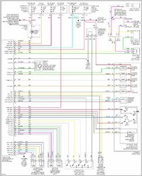
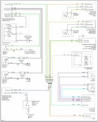
At least now this is understood. Given that, C3 is the flex harness connector, terminal B12 is NOT unfortunately a point of connection or probing for connection to the backup camera. for connection to use as BU camera. That helps me quite a bit. I may have to remove the BCM to locate the BU lamp feed that “passes” through to the main harness to the rear of the vehicle. I did not want to remove the BCM due to concern of the risk in damaging one of the connectors or wire terminations on each.

Attaching the backup camera 12v feed to one of the rear BU lights introduced too much effort in routing the camera feed especially as I presumed I would tie into the BU light feed INSIDE the vehicle.

Thanks again!!
un-fused


Prepared by @mrrsm for www.gmtnation.com on 05/29/2024
 

Jkb242

Original poster
Member
May 19, 2019
250
CLT
I think that information is already provided in my post.... C3 which is BK in color.... again assuming that info lines up with you vehicle as I can't guaranty that as it is "generic" to the year model that I have indicated.
Are you certain C3 is a wire connector? According to the reply from mean, C3 is the flexible printed circuit connector. Would appreciate if you could assist in clearing this up. Much thanks!
 

Jkb242

Original poster
Member
May 19, 2019
250
CLT
The member name I referenced was incorrectly entered as my phone “decide” on an “AI” spelling. Member referenced is mrrsm not mean. Sorry.
 
  • Love
Reactions: mrrsm

Jkb242

Original poster
Member
May 19, 2019
250
CLT
This effort was begun to address the installation of a rear backup camera for this vehicle. I have the option to switch in the camera and turn on the dash mounted monitor when backing. It’s working now but activated by a manually operated switch.

The attachment you provided is vey helpful and confirms what I have taken from the wiring diagram originally referenced in the OP. The feed from the BCM B12 ultimately connects to both BU light feeds. That’s all I need to complete this objective. I do not understand where I can access B12. I do not need the individual feeds to each BU LIGHT (Light green wires). The common supply feed at B12 is fine. Can you tell me which connector on the BCM houses B12 if in fact it’s in one of the two mass BCM connectors? If it passes through the fuse block as you state what color is it and which harnes is it in?

Thanks very much.
Throughout this effort in speaking assistance the support is very much appreciated from all who contributed. My vehicle (in my signature is 2006 Envoy Denali, Sport edition as it was called) would seem to be identical to the one you referenced, 2006 Envoy. But possibly my Denali trim code contains a different BCM layout, the SIGNIFICANT difference being connector C3. Could you please post a document page showing the location of C1-C3 on the vehicle you referenced(2006 GMC ENVOY)? This is likely the quickest and most accurate way to determine what I now need. determine the identity/location applicable to my vehicle in light of what I have been provided. Much thanks!
 

budwich

Member
Jun 16, 2013
2,139
kanata
Its not easy from the device that I use. Anyway, as explained, maybe your vehicle "version" is somewhat different than what is described. As I stated, the connector C3 is FW (ie. ribbon). Its color is BK. If you are not seeing that then there is nothing more I can add.

Knowing the "little" that I have experienced on my 2008, I think you are looking for something in some form that isn't there from the BCM. That's why I gave you the rest of the information about the other parts of the layout.

From my quick look at my BCM, the information provided in terms of connectors identificaiton is "identical". The pictures posted by mrrsm don't leave much doubt.

IF you have any doubts, look at ALL the information that has been provided... then count the pins. You will then come to the right conclusion yourself.... hint: there ain't any other "20 row" pin connectors on the bcm... at least in the pictures and the one in my truck.

ADDED...not to call you "foolish", but the picture that you posted about your BCM isn't any different than the other ones that have been posted.... yes the angle is different, but the connectors are not. Your picture only shows the C1 and C2 connectors.
 
Last edited:

Jkb242

Original poster
Member
May 19, 2019
250
CLT
Thanks sincerely. Since I know the BU light feed is not in either C1 or C2 but passes thru infused, it has to be in the harness below the BCM. I don’t think I’m going to risk damage to any of the connectors that must be removed. As a side note, the picture I posted was before I knew the identity of C1-C3. From the post by mrrsm I discovered only the identity of C3 and nor did I understand FW meant “flexable wire” until your post. The lack of documentation available for the BCM was my primary challenge in looking for the BU light feed location.
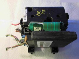
Thanks again to all!
 

budwich

Member
Jun 16, 2013
2,139
kanata
Thanks sincerely. Since I know the BU light feed is not in either C1 or C2 but passes thru infused, it has to be in the harness below the BCM. I don’t think I’m going to risk damage to any of the connectors that must be removed. As a side note, the picture I posted was before I knew the identity of C1-C3. From the post by mrrsm I discovered only the identity of C3 and nor did I understand FW meant “flexable wire” until your post. The lack of documentation available for the BCM was my primary challenge in looking for the BU light feed location.
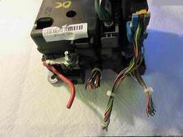
Thanks again to all!
I still think you don't understand.... :-(

There is lots of documentation... its been posted here.

As I indicated, you are trying to find something that isn't there. The information provided thru out this thread is "accurate". There is NO BU "direct" feed coming out of C1 or C2. It is sent out on C3. Your "idea" that you can easily tap into the wired connectors is your "imagination" or "desire"

As I indicated, the BU output is ONLY at C3. Not sure how much more can be said... BUT I will say more... :smile: you don't understand what a BCM does. It is a body control module. What does that mean? It gets commands from somewhere and then sends out commands and / or activates things. In this case, the BCM gets a command to activate BU lights, and, a big "AND", it sends out 12v on the C3 connector. There IS NO BU 12v sent into the BCM as the BCM is powered with 12V all the time. I hope that makes things a bit more clear and you can make your "easy design hook" work.
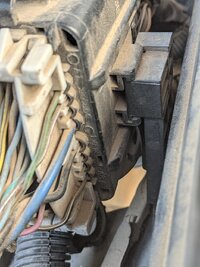
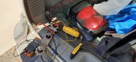
 

azswiss

Member
May 23, 2021
977
Tempe, AZ
Since I know the BU light feed is not in either C1 or C2 but passes thru infused, it has to be in the harness below the BCM.
There is no analog BU input into the BCM (or any other module) to tap into. The BCM is notified that trans is in Reverse via commands sent on the Class 2 Serial Bus on C1 pin B1 (L-GN 1037 Class 2 Serial Data). Upon seeing that notification the BCM applies 12V to C3 pin B12. You would need something along the lines of an Arduino bus sniffer to monitor the bus to know when the trans is in Reverse and then tie that to a relay for the analog output.
 

Jkb242

Original poster
Member
May 19, 2019
250
CLT
I still think you don't understand.... :-(

There is lots of documentation... its been posted here.

As I indicated, you are trying to find something that isn't there. The information provided thru out this thread is "accurate". There is NO BU "direct" feed coming out of C1 or C2. It is sent out on C3. Your "idea" that you can easily tap into the wired connectors is your "imagination" or "desire"

As I indicated, the BU output is ONLY at C3. Not sure how much more can be said... BUT I will say more... :smile: you don't understand what a BCM does. It is a body control module. What does that mean? It gets commands from somewhere and then sends out commands and / or activates things. In this case, the BCM gets a command to activate BU lights, and, a big "AND", it sends out 12v on the C3 connector. There IS NO BU 12v sent into the BCM as the BCM is powered with 12V all the time. I hope that makes things a bit more clear and you can make your "easy design hook" work.
Yes, I do understand as stated in my last response yesterday having reviewed all the helpful information provided by all. However, your last reply was over the top both disappointing and offensive. WHY?

I’m a graduate engineer although I am a DIY in terms of automotive repair however, electrical circuit theory and design has been my career since 1969. The theory and circuit behavior is the same. For the record, I do understand the general function of the BCM, but I did not have any information regarding BCM connector ID, nomenclature or routing regarding my initial post until the most recent replies yesterday.

Your assistance is much appreciated but your tone, demeanor and “put down” in your response today is not. It’s unnecessary and unwarranted. I wasn’t requesting or even expected a response from anyone as I clearly concluded in my last post that I did not choose to attempt connection to the C3 harness, therefore that effort is obviously abandoned.

I don’t understand the purpose of your response, since it included nothing constructive to the original objective. I have never been “talked down to” like this by anyone affiliated with this site. I’m sure you are a valuable contributor here and much appreciated but your response today is disappointing indeed.
 

budwich

Member
Jun 16, 2013
2,139
kanata
thanks... I think you used the term "dope out" first so I was following your lead along with your continual insistence that there was "limited information".

anyway, I hope you get your project completed.
 

Jkb242

Original poster
Member
May 19, 2019
250
CLT
Mrrsm, who responded to this thread, used the term “Doped out” not me.
Thanks….
 
  • Like
Reactions: mrrsm

mrrsm

Lifetime VIP Donor
Supporting Donor
Member
Oct 22, 2015
8,087
Tampa Bay Area
It would be a shame if anyone took offense to my use of the word "Dope" as I am an Old School USCG Aviation Machinist's Mate from the early 1970s (as well as being a Retired Homicide Detective after a 25 Year Police Career).

That expression refers to "Plane Doping"; a process of coating Fabric Airplane Wings with a sturdy hardening coating agent that made the wing surfaces more durable. THAT process was invariably ...Time Consuming ... hence the expression being used in this instance as "taking so long to Dope Out' the long list of the 3 BCM Connector Definitions.

I'm 75 Years Old... and if you follow the Socio-Psychological idea that 'WHAT You are...is WHERE you WERE...WHEN..." I am just as much a prisoner of the culture(s) and the idioms that I grew up with and learned during my long life as the next Man. So... No offense by the use of it ...was ever intended.

One last observation since this whole matter reflects poorly upon me is that whenever I post replies, you will NEVER see expressions like, "You're Wrong..." or "You are Mistaken" in counters to whatever entries others have posted or offered on any subject. The marvel of coming to GMT Nation and participating is that while it might be a Competition for the Best Ideas and Solutions to be discovered, it should never be my place to challenge others over matters that will ultimately be decided by the Original Posters. Any corrections that take place here are the exclusive provenance of the Admins and the Mods and they always know what is best for the Site and for us all.

The important thing is that the OPs obtain as much accurate information as possible... Hopefully As SOON As Possible and in many cases, they will decide for themselves what is relevant to their needs. Most of time, they get what they need and are quite pleased afterwards. But if it turns out that OTHER Contributing Members come closer to the mark than anything I might have added... Then BRAVO! Even Better! And a Thumbs Up to every Man and Woman who manages to Solve These Problems without any help from me!
 
Last edited:

TJBaker57

Member
Aug 16, 2015
3,018
Colorado
I have the wiring diagrams provided by Mooseman which are invaluable. The particular circuit I am looking for from the BCM is the backup lamp feed. From the particular diagram in the set, “External lamps/backup” I see the two light green wires feeding both backup lamps. The question is in which connector are these wires located at the BCM.. Light green is also a data line connection at the BCM. I understand I could probe each of the light green wires for 12v when in reverse but was hoping to avoid that or removing the rear light lenses to access and confirm that circuit. My driveway is a 10 degree slope and taking it out of park isn’t safe since I’m working alone.

Identifying which connector at the BCM for these wires would be very helpful.

Much thanks!


I see I am late to the thread here, life (& death) happens and sometimes interrupts what had become the usual existence.


A lot has been tossed about and I 'might' have something of use to add here.

I set about this morning digging around in some resources I know of and came up with more diagrams. One specific diagram, and the fact we have a GMC flavor of the GMT360/370 might bear fruit. Have a look at this..


After you get familiar with the diagram note that after the backup lamp power exits the rear fuseblock there are 2 variations of the wiring. On the left we have the Chevrolet, Buick, etc and on the right we see a GMC variant.

The diagram for the GMC variant shows the circuit (#24) passing through the C101 connector. The other more common variant does not.

The C101 connector is the large (38 way?) connector alongside the underhood fuse block.

I can state that my own 2002 model year TrailBlazer built in 10/01 indeed does not have any wire in terminal number A7 of C101.

Only someone with access to an Envoy can check to see if those indeed have such a wire routing through there.

If yes then there is your access point for backup lamp power in an Envoy.


Here is the C101 connector details for a 2006 Envoy 5.3 4WD. (it appears the same as the 4.2)


And here is a look at my own C101 showing no wire at A7. The designation "A1" can be seen giving a starting point for reference.

PXL_20240602_170443901.NIGHT.jpg


To try and determine where my own backup lamps circuit runs I removed my rear lamps and connected a signal tracker to the circuit then used the probe to see the routing. In my vehicle, a TrailBlazer, the circuit diverges in or near the rear fuse block and one direction travels forward, up the left B-piller, across the headliner to the inside rearview mirror. The other branch travels beneath the carpet passing by the left rear wheel well then into the cavity behind the interior panel and back to the left rear lamp assembly. I did not chase down how it gets to the right rear lamp assembly but did detect a strong signal below/inside the right rear interior storage compartment.

20240602_131812.jpg


Now then, what if your vehicle is NOT a GMC? What can you do then?

Supposing you are going to run a wire from the BCM/rear fuseblock area up to your equipment in the dash somewhere, if you ran such wire under the carpet near the drivers door you might be able to splice into the harness that runs up the B-pillar. ?? That could be messy and open the possibility of corrosion down the line.

I think I would instead get myself another flat cable at the BCM and tap into that. I think that could be done fairly cleanly. That little cable is easily obtained at a u-pull yard and both ends can be removed without much trouble. The wider end offers pretty good access to the contacts.

Just lost power here so I am going to post this much now. Might have more to add later...
 
Last edited:
  • Like
Reactions: azswiss and mrrsm

mrrsm

Lifetime VIP Donor
Supporting Donor
Member
Oct 22, 2015
8,087
Tampa Bay Area
Sweet! Saved them as PDFs for ERZ Zooming In & Out:

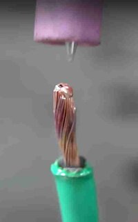
Also... Having recently obtained a 600 Watt Micro-Pulse Spot Welder and gradually learning more about its performances characteristics...besides being able to weld Aluminum, S/S, Titanium, Platinum and Gold... it will all also work very nicely on Copper Wires, too... So once Melted and then Pounded FLAT on the Ends...joining the involved Wire(s) to the Flat 12Kt Gold Tines of the Green Flexible Ribbon seems very doable:

COLDWELDEDCOPPERWIRE.jpg


Attachments

  • Exterior Lights Diagram 8 — 2006 Chevy Truck TrailBlazer 4WD L6-4.2L VIN S Service Manual Oper...pdf
    44.5 KB · Views: 0
  • C101 — 2006 GMC Truck Envoy 4WD V8-5.3L VIN M Service Manual Operation CHARM.pdf
    134.3 KB · Views: 1
Last edited:

Mooseman

Moderator
Dec 4, 2011
25,836
Ottawa, ON
Of course! The GMC Envoy has different backup lights that are in the rear bumper instead of in the rear light cluster. That would explain the difference in wiring between the GMC and all other GMT360/370.
 

TJBaker57

Member
Aug 16, 2015
3,018
Colorado
Of course! The GMC Envoy has different backup lights that are in the rear bumper instead of in the rear light cluster. That would explain the difference in wiring between the GMC and all other GMT360/370.

Thanks Mooseman! I was just now wondering WHY would the Envoy be different!
 

Forum Statistics

Threads
23,567
Posts
640,680
Members
18,868
Latest member
jonu

Members Online