LED Array

Gump2773

Original poster
Member
Feb 21, 2012
147
I know there is a bunch of posts about LED's, but they seem to get jumbled all together. Feel free to move this if need be.

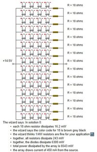
My question is does this look correct? Its the easiest way for me to soak it all in.
View attachment 19345

Math is my last concern although the calculator said this was correct. Im just looking to understand how to wire these. :confused:
 

Attachments

  • ledwiring.jpg
    ledwiring.jpg
    53.7 KB · Views: 12

kardain

Member
Dec 16, 2011
557
I trust the site you got that screen capture from, so it is correct.... The resistor value is low enough you can probably forego it.

Here's how I would wire it up....

Go to radio shack and get a large perforated board and some solid core thin wire. Go to the hardware store and get some solder flux from the plumbing section (it should be near the copper pipe, if not they need to put it there) and some liquid electric tape.

Press assemble your array in the perf board so you can trim it to size, remove the leds and cut down the perf board.

Solder your leds just like the diagram, the long legs are positive.

Take a piece of the solid core wire, strip down most of the insulation and tie all the remaining positives together (just like that vertical line in your screen capture), leaving enough slack on one end to tie in to your power source. Do the same for grounds.

Apply some liquid tape to the soldered portion of the wire to prevent shorts.

Tie the power and ground tails to your source and test.
 

Gump2773

Original poster
Member
Feb 21, 2012
147
kardain said:
I trust the site you got that screen capture from, so it is correct.... The resistor value is low enough you can probably forego it.

Do you mean do this without resistors?
 

kardain

Member
Dec 16, 2011
557
Gump2773 said:
Do you mean do this without resistors?

Yes. 18 ohm is a negligible drop. However if you feel more comfortable adding them in, you can. If space is a concern, they can be left out. Since LEDs have a min/max range as well as an optimal voltage, if you used the optimal voltage when entering the values on the site there is enough of a buffer on the max end to safely forego using the resistors.
 

STLtrailbSS

Member
Dec 4, 2011
1,617
Well I know what im doing tommorow on my day off, gotta grab some solder. :thumbsup:
 

DJones

Member
Jan 21, 2012
701
St. Petersburg, Florida
kardain said:
Go to radio shack and get a large perforated board and some solid core thin wire. Go to the hardware store and get some solder flux from the plumbing section.

Go to Radio Shack and get a large perforated board and some solid core thin wire. While at Radio Shack, get some solder flux also.

Fixed it.

Actually, most solders are rosin-core, so flux is built-in.
 

kardain

Member
Dec 16, 2011
557
DJones said:
Go to Radio Shack and get a large perforated board and some solid core thin wire. While at Radio Shack, get some solder flux also.

Fixed it.

Actually, most solders are rosin-core, so flux is built-in.

I've yet to find flux at radio shack (darn mall franchises and their limited stock)... Just at the local hardware store. But if radio shack has it, might as well save a trip. Even with rosin core solder, the extra flux doesn't hurt any.

If flux is used, a diluted rubbing alcohol bath will clean it up.
 

Gump2773

Original poster
Member
Feb 21, 2012
147
Well now, i wish i could find somewhere to buy 5mm flat head green led's locally.

By the way has anyone ever dealt with green for map/courtesy lights? Also, my 02 TB has 2 lamps above each door 1 thats turns on with a press and the other when the door is open. Should I just remove the tap light bulb and wire these leds's into the courtesy plug?
 

Shdwdrgn

Member
Dec 4, 2011
568
What are the ratings for the LEDs you plan on using? The image you posted claims 6300mW used by the LEDs in the array, and if you divide that by 60 pieces at 14.5V, you get 7.2mA. That seems extremely low, considering my high-brightness LED's take 25-30mA. Most LED setups for automotive use run the LEDs in series of 3, not 4, with a small value resistor to dial in the final amperage, because this arrangement nicely divides the power to each set while still allowing the use of a low-value, low-cost resister.

I would highly recommend you wire together a single set of 4 LED's in your planed configuration, hook them up, and see if the brightness is what you expected. My guess is that these are going to be too dim to be useful.

Also if you plan on trying this circuit without any resistors, again test with just a single set and not the whole array! I may be wrong, but I do not believe LEDs have any internal current-limiting. If this the case, and you hook it up without any resistor at all, you will blow out all four LEDs in one shot. Better to blow 4 in a test-run than blowing all 60!
 

Shdwdrgn

Member
Dec 4, 2011
568
Gump2773 said:
Well now, i wish i could find somewhere to buy 5mm flat head green led's locally.

Just take a dremmel and grind off the top of the LEDs. As long as you don't cut deep enough to get into the visible wires inside the LED, you are just cutting plastic and will not affect its functionality. I did this for a number of my dash lights to give a more dispersed output rather than a spotlight effect.
 

kardain

Member
Dec 16, 2011
557
Shdwdrgn said:
but I do not believe LEDs have any internal current-limiting

They do have current limiting, however it isn't much. The data sheet here shows a 2.8 minimum voltage to a 4 max voltage, with 3.6 being optimal.

http://www.superbrightleds.com/more...ed-32-degree-viewing-angle-7500-mcd/272/1199/

4 @ 3.6 = 14.4v. The 18ohm resistor in the original diagram is due to using 14.5 as the input voltage. As long as overvoltage is less than 15.5, an inline resistor is not required for a 4 diode series based on the data sheet.
 

Forum Statistics

Threads
23,357
Posts
638,396
Members
18,567
Latest member
Adungyyy

Members Online