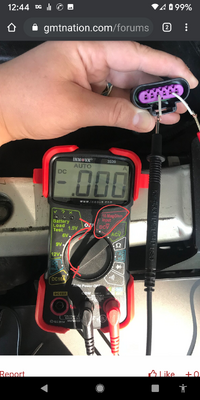
nah... you are looking at the resistance post... I was referring to his "voltage measurement". As for his resistance post, he is on the wrong pins, it has little to no meaning.
You are using an out of date browser. It may not display this or other websites correctly.
You should upgrade or use an alternative browser.
You should upgrade or use an alternative browser.
NEED HELP Fan Clutch from hell lol
- Thread starter Aec678
- Start date
christo829
Member
I was going off of TJ”s posts #10 & 11, jus got this meter and don’t know what I’m doing lol, what should it be set to read the 5v dc?you might want to check your settings... you are set to read CURRENT in the posted picture....
PLUS you are in the WRONG pins. Check the posted pinout carefully. You need to measure from ground.
Not getting 5V Dc in that position, could that mean the two gray wires got swapped?View attachment 96769
Those are the correct terminals. Is the key in the RUN position here? Even if the gray wires were swapped your meter would still display voltage, only difference would be the display of a negative voltage (-5.00) indicating reversed polarity.
You could try connecting your meter negative probe to chassis or battery ground and then try each connector terminal, looking for the power signal.
Edit: as Budwich commented your meter is set to the wrong position in this picture. Need to be set to DC Volts
I was going off of TJ”s posts #10 & 11, jus got this meter and don’t know what I’m doing lol, what should it be set to read the 5v dc?
OK... Stop what your doing!!
Hooking up a test meter CAN damage things if connected incorrectly. Luckily ~many~ test meters are internally fused so more often than not only one of the meters fuses blows out. But if you were to short out some circuit of the PCM I'm not sure it couldn't cause damage. (see edit below)
My post #10 is reading DC Volts from the vehicle harness. Take note of the FEMALE terminals.
My post #11 is reading resistance (Ω) and I am reading from the fan clutch harness . Take note of the MALE pins.
EDIT: I just had a closer look at your meter and noted that the DC10A current test lead socket is UNFUSED!! My recommendation is to NEVER use that socket to connect your test lead to. My meters have that port fused and I blow the damn fuse regularly by forgetting to put the test lead back to the normal location.
Last edited:
Not sure if I’m doing this right lol, this is what I got..
don’t seem to be getting anything...not sure if I’m checking this correctly View attachment 96770
Try this....

Ok I’ll check that out tomorrow morning, thanks for all the info! Learning new things every day lol
The key was in the run position, engine off.Those are the correct terminals. Is the key in the RUN position here? Even if the gray wires were swapped your meter would still display voltage, only difference would be the display of a negative voltage (-5.00) indicating reversed polarity.
You could try connecting your meter negative probe to chassis or battery ground and then try each connector terminal, looking for the power signal.
Edit: as Budwich commented your meter is set to the wrong position in this picture. Need to be set to DC Volts
something is very "strange".... what the heck is going on? post 33 shows a picture of the connector along with pin designations which people indicate is correct. The ground pin is the first one in the set. The OP has wires no where near where a ground can be picked up.
something is very "strange".... what the heck is going on? post 33 shows a picture of the connector along with pin designations which people indicate is correct. The ground pin is the first one in the set. The OP has wires no where near where a ground can be picked up.
He is testing for the presence of the 5 volt and low reference of the hall sensor. The code he is troubleshooting is for no speed signal from the fan clutch. Not presently interested in the ground and or power to the clutch solenoid valve which would be terminals A & B.
.... but you need to measure a voltage to a KNOWN ground otherwise you will likely get nothing out of your test reading... you won't be able to tell if there is no 5v or no low reference.
Agreed! That's why I added the blurb in post #44, 2nd paragraph

JayArr
Member
but you need to measure a voltage to a KNOWN ground otherwise you will likely get nothing out of your test reading... you won't be able to tell if there is no 5v or no low reference.
When I test a circuit like this I test with the connectors together (wiring harness to clutch) and I probe from the back of the connector, go steal two of your wife's sewing pins. That way what I'm actually measuring is the voltage across the hall sensor. If I get 5V then I know that the 5 volt supply is OK AND I know the circuit is grounded through the low reference wire and the ecm.
The trouble with using chassis ground on these kinds of circuits is that the 5V you are measuring is generated inside the ecm using an electrical circuit called a buck regulator, it converts 12V to 5V. The ground of that circuit doesn't have to be the same as chassis ground, it can float. I don't know if it does on the Envoy but it can.
Don't assume that the 5V ground is the same as the 12V ground.
When I test a circuit like this I test with the connectors together (wiring harness to clutch) and I probe from the back of the connector
That would be my second test. If testing the source is as easy as it is here I begin with confirming power availability and then move on to see if it can hold the load.
Since in this case we are investigating a "no signal" from hall sensor condition my 1st test would be power availability and proper polarity, other tests would be for a closed circuit for that power through the hall sensor, closed circuit for the signal return from hall sensor, reconnect harness and check for return signal from hall sensor.
Everyone has their way of getting a job done.
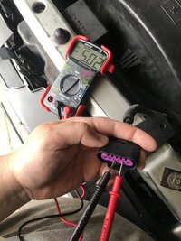
Ok, I tried it in that position and got the 5V. Is it safe to assume that the new wire harness is wired correctly then? (Only the 2 gray wires were questionable) The replacement fan clutch should be here by Wednesday, hopefully that solves the problem... sorry I haven’t been able to get back in this till now, life has a way of changing my priorities Lol...

Ok, I tried it in that position and got the 5V. Is it safe to assume that the new wire harness is wired correctly then? (Only the 2 gray wires were questionable) The replacement fan clutch should be here by Wednesday, hopefully that solves the problem... sorry I haven’t been able to get back in this till now, life has a way of changing my priorities Lol...
View attachment 96907
Nope! See the negative sign before the 5.02 on your meter? The polarity is reversed. Will not work that way. Need to swap those 2 wires.
Damn! I didn’t even notice that! Ok so I need to swap the two gray wires, thanks TJ for all your knowledge and help!Nope! See the negative sign before the 5.02 on your meter? The polarity is reversed. Will not work that way. Need to swap those 2 wires.
Also is there anything else I should check before I install the new fan clutch?Damn! I didn’t even notice that! Ok so I need to swap the two gray wires, thanks TJ for all your knowledge and help!
Also is there anything else I should check before I install the new fan clutch?
I suspect that as soon as those 2 gray wires are swapped to their rightful position it wll all work as it should!
