It's no *SECRET* that my preference in Automotive Diagnostics leans heavily towards using Automotive Oscilloscopes. But... Their USE is invariably applied in conjunction with The USE of Other Basic Hand and Diagnostic Tools such as a Lighted Probe and either a DMM or a DVOM.
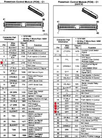
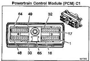
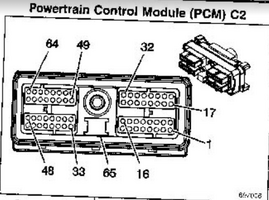
The Big Take Away here is that this effort must always include a Basic Understanding of the Systems involved, and their Wiring Diagrams. You don't necessarily NEED any Exotic Equipment to be a Good Diagnostician... until you are trying to VISUALIZE problems in any Electrical Paths that are So Brief and So Transient that the typical DMM will NOT be able to catch any useful views of these events...as Wave Forms... even if your DMM is fitted with a Min-Max Feature.
All That Said... Folks like @TJBaker57 and @budwich will often dial right in on the Who, What, Where, Why and When of certain Electrical issues because they KNOW what they are doing within the realm of Auto Diagnostic Step BY Steps. They have proven and often explained that Understanding the Basics of Electricity and using Common Sense and Good Judgement will more than likely Win The Day and nail down what the REAL issues are in finding and fixing such problems.
THESE Videos are Universal Examples in direct support of what you can always find in all of their Threads and Posts at GMT Nation based upon this premise
"ELECTRICITY IS THE SAME ...NO MATTER THE MAKE OR MODEL OF THE VEHICLES INVOLVED..."
Last edited:

