Arduino Chat

TJBaker57

Original poster
Member
Aug 16, 2015
2,897
Colorado
Not too long ago @itstallion posted about installing a power steering system from an Equinox into a project of his. The task invloved using an Arduino to do some communication tasks in order to enable the power steering unit to activate and come to life.

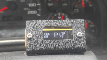
I had long had an idea to use an Arduino or maybe Raspberry Pi to read a sensor or two and transmit the data to apps like Torque Pro, OBD Fusion, Car Scanner ELM & OBD, and so on. Any app that allows for user entered PID definitions. The sensor data would be sent over the existing serial data bus and as such would be displayed by the phone (or tablet) right alongside the standard factory sensor data that the vehicle provides.

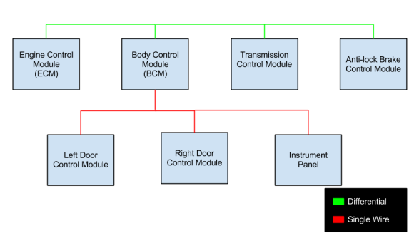
It would only work with vehicles using the GM implementation of the SAE J1850 VPW protocol commonly referred to as the "serial data" line. I have a fair understanding of the J1850 message structure so I felt comfortable with that part. I know nothing of CANBUS protocol so I wouldn't even attempt to do anything with that.

Arduino however was and is a whole new ballgame for me. itstallion provided the final boot in the rear that got me started thinking that just maybe I could do this myself and stop looking for someone else to take the idea and make something of it.

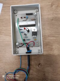
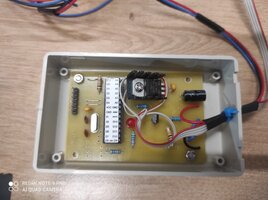
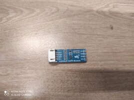
I am no electronics engineer nor programmer so I had to seek out circuitry and portions of code from around the web and staple it all together with the code shared by itstallion. Many things were altered in the codes I used and a few different circuits were tried out then altered and retried. The code is certainly not pretty, but at the moment does what I was looking to do. I tried to use optocouplers for interfacing with the vehicle data bus but eventually settled on some circuitry taken from the ELM327 datasheet.

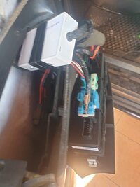
And so here I am several months later and while there is still a lot more to do I at least have something to play with that works in both my 2005 Yukon and my 2002 Trailblazer. Nothing fancy yet, just using a thermistor that I already had on hand and just taping it to a radiator or heater hose so it's not yet a very accurate reading but it's something.

IMG_20220310_201812.jpg

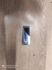
The Arduino board seen here is a Nano though I used an Uno and a SparkFun Redboard version during the trials. Not shown in this image is the thermistor or it's connections. Far from a finished item, I expect I will continue to add this or that and simply fiddle with the thing. Next thing I'd like to do is get a proper temperature sensor and maybe cut in a sensor well into a heater hose to get a better reading.

@Saleh what questions were you looking to ask?? I titled this thread "Arduino Chat" thinking we didn't have such a thread yet.
 

Saleh

Member
Mar 10, 2022
6
Qassim
Thank you @TJBaker57

Okay, this might be very long but it will be in 2 parts.
Please correct any typing mistakes, as this is not my first language.


Part 1: I'm an IT student, currently making an Android App to scan cars, live data, supported PIDs, Read/Clear DTC, Scan other modules and hopefully controlling some of the car's features.

right now I feel stuck in few things. I love cars and I love creating apps but I had no knowledge in cars, I did gain a lot of information because of this but it's still not enough to do exactly what I want.


Part 2: At first I thought that I can simply control and car using a cheap Elm327 adapter and do some coding, it's way harder than I imagine and requires some hardware (eg. Arduino) and things that I have never heard of before.

First of all I wanted to start from the scratch to understand everything, Right now I have a working app it has a Terminal and it does work!

I wanted to add a "Read/Clear Trouble Codes" which is sending the command (03) to get DTC and (04) to clear DTC.
I found out that it only get OBD2 codes and what I mean by that.. I used another app and I found that my coworker car has 14 DTCs, my app only showed me 1 DTC, in the other app under OBD2 codes there were only 1 DTC which my app managed to get but the other 13 codes in the other app were under ABS/SRS/BCM/... and there were like around 15 modules not all had DTC but it was like a list of modules and every module has below it the DTC if it had any.

Now to the big question how DID that app read more codes than my app, it must have used a different commands to get to the others modules. I need help in that.


Right now I'm waiting for my Arduino Uno + MCP2515 to be delivered to me hopefully sooner than later.
I also have a 2 Elm327
1 very cheap it's very bad doesn't support all the commands and I took from my brother.
I have bought a very good one which is Veepeak BLE+ from amazon and it's really good it supports all the commands. it's elm327 V2.2 if anyone interested to know.


now to the most important question:
I already know that there are commands needs to be send like
ATZ reset all
ATH1 Headers On
ATL1 allow long message
ATMA Monitor All

I think getting to the wanted module has to be doing something with sending the command (AT SH xx yy zz) then sending a another Hex number but I have no idea what I should put in the xyz to get to the module that I wanted there are no data anywhere!
are cars all the same? is there like a file or a list I can lookup from it because I haven't found anything.
 
Last edited:

TJBaker57

Original poster
Member
Aug 16, 2015
2,897
Colorado
I see you have ordered a CAN controller, MCP2515. I have no knowledge of CANBUS so unfortunately I will be of very little help there. Currently I think one thing you should read first is the datasheet for the ELM327 from ELM electronics. This document will explain much of what you are asking about message addressing and so on.

 
  • Like
Reactions: Mooseman

Saleh

Member
Mar 10, 2022
6
Qassim
I see you have ordered a CAN controller, MCP2515. I have no knowledge of CANBUS so unfortunately I will be of very little help there. Currently I think one thing you should read first is the datasheet for the ELM327 from ELM electronics. This document will explain much of what you are asking about message addressing and so on.

Yeah this file has a lot of good information but not the ones that I'm currently looking for.

For example I just found this, I believe this was for Chevrolet.
but I'm not really sure if this is correct or not.

AT SH 6C xx F1the AT command that need to be sent
AT SH 6C 10 F110 = ECM (main engine brain)
AT SH 6C 28 F128 = ABS
AT SH 6C 40 F140 = BCM (body control module)
AT SH 6C 58 F158 = Airbag Module
AT SH 6C 60 F160 = IPC (instument panel cluster)
AT SH 6C 62 F162 = Hud
AT SH 6C 80 F180 = Radio
AT SH 6C C0 F1C0 = Immobilizer
19 C2 FF 00Current Codes
19 D2 FF 00Current and Pending Codes
6C F1 58 59 81 00 13 99This is a response.
AA BB CC DD EF GH IJ KL
AA = Node to node​
BB = Adress to scanner you're using​
CC= Witch part the code is located in. Engine,trans,abs,airbag m.m.​
DD= This I'm not sure about​
E = First part of the code​
F = Second part of the code​
G = Third part of the code​
H = Fourth part of the code​
IJ= Status of the code 00=god 11=and up eq.fault​
KL= Checksum of the code just ignore this one​
 

TJBaker57

Original poster
Member
Aug 16, 2015
2,897
Colorado
Yeah this file has a lot of good information but not the ones that I'm currently looking for.

For example I just found this, I believe this was for Chevrolet.
but I'm not really sure if this is correct or not.


Almost all of the command strings in the table you posted are for use with a GM vehicle only, likely earlier than 2008, that uses the SAE J1850 VPW protocol. Some of it is correct and some is not. None of them are correct for a CAN bus vehicle.

The MCP2515 you ordered is for a CANBUS vehicle. That device will not work for vehicles that are using the SAE J1850 VPW protocol, except in the case of vehicles that are running multiple protocols.

Are the vehicles you are asking about General Motors vehicles communicating with the SAE J1850 VPW protocol?? Can you tell us a specific vehicle that you are working with, year, make, model, and engine?

If yes than we can discuss these commands in a more appropriate thread where this is discussed in detail.


Saleh

Member
Mar 10, 2022
6
Qassim
Almost all of the command strings in the table you posted are for use with a GM vehicle only, likely earlier than 2008, that uses the SAE J1850 VPW protocol. Some of it is correct and some is not. None of them are correct for a CAN bus vehicle.

The MCP2515 you ordered is for a CANBUS vehicle. That device will not work for vehicles that are using the SAE J1850 VPW protocol, except in the case of vehicles that are running multiple protocols.

Are the vehicles you are asking about General Motors vehicles communicating with the SAE J1850 VPW protocol?? Can you tell us a specific vehicle that you are working with, year, make, model, and engine?

If yes than we can discuss these commands in a more appropriate thread where this is discussed in detail.


I have 5 Cars they are all Gasoline:
1- Honda Accord 2013 V4 (LX-B or EX)
2- GMC Yukon 2010 V8 5.3L SLE
3- GMC Sierra 2009 V8 5.3L 1500 Base
4- Toyota Land Cruiser 2013 V8 4.6L GXR
5- Mercedes S350 2008 V6 AMG
 

TJBaker57

Original poster
Member
Aug 16, 2015
2,897
Colorado
I have 5 Cars they are all Gasoline:
1- Honda Accord 2013 V4 (LX-B or EX)
2- GMC Yukon 2010 V8 5.3L SLE
3- GMC Sierra 2009 V8 5.3L 1500 Base
4- Toyota Land Cruiser 2013 V8 4.6L GXR
5- Mercedes S350 2008 V6 AMG


I think those will all be on some version of CANBUS. Possibly ISO 15765-4 protocol. A different message structure than what you are seeing here.
 

Saleh

Member
Mar 10, 2022
6
Qassim
I think those will all be on some version of CANBUS. Possibly ISO 15765-4 protocol. A different message structure than what you are seeing here.
Okay, but how can or from where can I get more details to start working, all I have are just Hex numbers with no information and I have no idea what they are for or what they mean..


Yes you are correct, They all use this protocol ISO 15765-4 which is number 6 if I send they command ATDPN

is there like a guide or a start point that will help me start getting the information that I want?


it feels like that I'm trying to read Japanese with no access to translations, you know what I mean?
 
  • Like
Reactions: TJBaker57

TJBaker57

Original poster
Member
Aug 16, 2015
2,897
Colorado
feels like that I'm trying to read Japanese with no access to translations, you know what I mean?

I do indeed know what you mean. It took me several years to seek out and begin to understand informations pertaining to SAE J1850 VPW. As I have stated many many times my knowledge of CAN is practically zero. I do not know where to even begin with ISO 15765 except to say that the ELM327 datasheet does at least begin to describe how to request Diagnostic Trouble Codes on a CAN system.
 

mrrsm

Lifetime VIP Donor
Supporting Donor
Member
Oct 22, 2015
7,639
Tampa Bay Area
A Related Thread for the Use of an Arduino Device to Transfer Mileage intact between Two Instrument Panel Clusters:

 
  • Like
Reactions: TJBaker57

mrrsm

Lifetime VIP Donor
Supporting Donor
Member
Oct 22, 2015
7,639
Tampa Bay Area
@TJBaker57 ... If you ever decide to branch out from the Class 2 Networks Solid PID Apps Work you've been so successful working on and want to investigate the CAN-Bus Networks HI-LO Data Packets for their Module Information, THIS Arduino DIY Project appears quite easy to do and looks very promising for future CAN-Bus Network Diagnostics and Problem Solving:


santon

Member
Jun 3, 2020
93
Israel
Very interesting thread! I also started to experiment with J1850VPW. To interface the Arduino UNO to J1850 bus, I built a simple 3 transistor interface published here. As a library, I am currently use this one. To work with the above 3 transistor interface, this library should be set to ACTIVE_LOW during the initialization in the sketch. Here you can see the Arduino controls the gauges of the TB instrument cluster. (Not all stepper motors are OK in this cluster).
 
Last edited:

mrrsm

Lifetime VIP Donor
Supporting Donor
Member
Oct 22, 2015
7,639
Tampa Bay Area
There are enormous resources available for creators of Arduino and Raspberry PI Projects who more often than not, park their 'Works In Progress' by storing them either locally or remotely in repositories.

GITHUB tries to keep track of all the "Pulling" and "Pushing" of "Commits" on such efforts that define What is being Stored in Repository "Branches" along with any Changes that have been made. This is critical when Developers need to keep track of their Code Changes along with any Changes made by other contributors "...On Different Branches".

However, from time to time, this can get very confusing and frustrating to navigate effectively when things don't "Stay on Their Branches" and go sideways. THIS Dude (A Young Microsoft Employee) puts on an excellent GIT vs. GIT-HUB Clinic, explaining the Basic Concepts and how to use the Command Line inputs that can help straighten out these confusing concepts:

 
  • Like
Reactions: christo829

santon

Member
Jun 3, 2020
93
Israel
If anybody is interested- here's a finished window roll up module based on Atmega microcontroller. We developed this module together with a friend. Here is the video of this device in action. It installed near the driver's module and uses a "lock" signal for the driver's door as a trigger and rolls up all 4 windows sequentially by sending the commands to serial data bus when the car is locked.
 

Attachments

  • window roll up module7.jpeg
    window roll up module7.jpeg
    115.2 KB · Views: 20
  • window roll up module1.jpg
    window roll up module1.jpg
    295.7 KB · Views: 21

mrrsm

Lifetime VIP Donor
Supporting Donor
Member
Oct 22, 2015
7,639
Tampa Bay Area
For any Interested Arduino Newbies:


mrrsm

Lifetime VIP Donor
Supporting Donor
Member
Oct 22, 2015
7,639
Tampa Bay Area
Okay... So now after you get your feet wet with the Arduino Board, IDE Software and General Programming Concepts... You WILL need "More Goodies"...And I mean A LOT MORE GOODIES!

So rather than Hunt & Peck your way around looking for a Whole Bird's Nest of things that will eventually provide you with EVERYTHING you need ...One at Time... Consider spending a Little Jingle over on Amazon and getting what they call:

"THE Most Complete Starter Kit UNO R3 Project"

You can find IT (For Only $60.00) and Whole Lot More Like IT ...over at THIS Link:


81fcyIo-o7L._AC_SL1500_.jpg

71WU0eAi-fL._AC_SL1500_.jpg


And here are some "Un-Boxing" Images of what this Kit looks like (in hand)

ELEGOOARDUINOKIT1.jpgELEGOOARDUINOKIT2.jpgELEGOOARDUINOKIT3.jpg

What's in the box?​


  • 5pcs White LED 5pcs Yellow LED 5pcs Blue LED 5pcs Green LED 5pcs Red LED 1pcs RGB LED 5pcs 22pf Ceramic Capacitor 5pcs 104 Ceramic Capacitor 2pcs Photo resistor 1pcs Thermistor 5pcs Diode Rectifier (1N4007) 2pcs Electrolytic Capacitor (10UF 50V) 2pcs Electrolytic Capacitor (100UF 50V) 5pcs NPN Transistor (PN2222) 5pcs NPN Transistor (S8050) 1pcs Tilt Switch 5pcs Button (small) 1pcs 1 digit 7-segment Display 1pcs 4 digit 7-segment Display 1pcs Sound Sensor Module 1pcs LCD1602 Module ( with pin header) 1pcs IC L293D 1pcs IC 74HC595 1pcs Active Buzzer 1pcs Passive Buzzer 1pcs RTC Module 1pcs DHT11 Temperature and Humidity Module 2pcs Potentiometer 1pcs Rotary Encoder Module
  • 1pcs Joystick Module 1pcs Keypad Module 1pcs 5V Relay 1pcs IR Receiver Module 1pcs UNO R3 Controller Board 1pcs Breadboard 1pcs Servo Motor (SG90) 1pcs Stepper Motor 1pcs ULN2003 Stepper Motor Driver Board 1pcs Prototype Expansion 1pcs Power Supply Module WARNING: Pls. do not use the voltage higher than 9V 1pcs HC-SR501 PIR Motion Sensor 1pcs Ultrasonic Sensor 1pcs GY-521 Module 1pcs 3V Servo Motor 1pcs MAX7219 Module 1pcs Remote 1pcs 9V 1A Power Supply 1pcs 65 Jumper Wire 1pcs Water Lever Sensor 1pcs USB Cable 1pcs 9V Battery with DC 1pcs RC522 RFID Module 10pcs Resistor (10R) 10pcs Resistor (100R) 30pcs Resistor (220R) 10pcs Resistor (330R) 10pcs Resistor (1K) 10pcs Resistor (2K) 10pcs Resistor (5K1) 10pcs Resistor (10K) 10pcs Resistor (100K) 10pcs Resistor (1M) 20pcs Female-to-male DuPont Wire
 
Last edited:
  • Like
Reactions: christo829

TJBaker57

Original poster
Member
Aug 16, 2015
2,897
Colorado
I skipped the starter kits as I had no use for things like joysticks for example.

I have acquired 6 Nano boards, an Uno board and a SparkFun version of the Uno, a half dozen or so clock modules, SD (micro) card modules, Bluetooth modules, beepers, solderless and soldered breadboards, spools of wire suitable for use as breadboard jumpers, several assortment packs of resistors, diodes, capacitors, transistors, linear regulators, etc., etc.

Besides the J1850 project I have made a logger for our well pump so we can monitor the runtime. Some of the neighbors wells have run dry so I wanted to get a handle on what sort of useage we have. It records the runtime of the well pump on an SD micro card and I retrieve the logfile over Bluetooth. If the well pump runs longer than a limit I set a beeper activates to alert us to a possible issue like a leaking toilet or the like. Next step would be to enable it to turn off the pump in such a situation where we were not home to hear the beeper and investigate the issue.

I continue to poke away at the J1850 code, tweaking here and there as I learn. What I am using is a jumble of code portions from here and there at sites like Github. The other day I found a programming error in a code that is often mentioned by people looking to interpret J1850 serial data.


As published, after a minor change or two to make it suitable for our GM applications, I discovered it tosses out 12 byte messages when it should not. 12 byte messages are valid. It is a simple oversight in comparison operations and there is practically NO chance it would affect anyone but it is an error nonetheless. Have been wondering if it is even worth mentioning to the developer since the project is not really active for about 10 years now.
 

mrrsm

Lifetime VIP Donor
Supporting Donor
Member
Oct 22, 2015
7,639
Tampa Bay Area
Here is an interesting Article on "How To Build an Arduino CAN Bus Analyzer" (with Programming CODE outlined):

 
Last edited:
  • Like
Reactions: christo829

AmpOverload

Member
Jul 10, 2023
106
USA
@TJBaker57: Jumping into this thread to continue a conversation begun in this post. (I hope that this thread is the appropriate place.)

Earlier this year, I began a long-desired project to implement what I call "HVS-VPW". It's a "Hardware Vehicle Simulator" for a VPW-protocol vehicle. In my case, it will usually be simulating a Buick, but it could be any VPW-protocol vehicle.

In order to get to the relevant point, I'll skip some of the background and details, but the hardware part of the project is now a reality, despite my limited time to really use it to the full potential and further develop the firmware (etc).

Long ago, instead of going the Arduino path, I decided to get really deeply into microcontrollers, specifically Atmel AVR microcontrollers, which is what the early Arduinos (and, IIUC, many [most?] of them still today) use. (I still want to experiment with Arduinos and hope to find time some day.)

But back to HVS-VPW. I had to figure out what to use as a baseline for both the VPW hardware and the firmware to drive it. I spent considerable time looking into various solutions (including the ELM327 datasheet) and settled initially on a circuit and firmware by Bruce Lightner. Some folks here may have heard of him. He designed a very cool circuit (and wrote firmware for it) that won a 2004 electronics design contest. His design and code was published in the Oct 2005 issue of "Circuit Cellar" (electronics) magazine. It used an Atmel mircocontroller (an older version of what is probably used by your Arduino board) to compute fuel efficiency and display it on a modified analog tachometer gauge. For anyone interested, Bruce's website is here:

https://www.lightner.net/lightner/bruce.html

(And, in fact, Bruce's article about his project is the place where I first read about using the stoichiometric air-to-fuel ratio with Mass Air Flow [MAF] to compute fuel use, something I recently referred to in the "Torque PIDs" thread.)

And fortunately (since Bruce's link to the Circuit Cellar article is dead now), he hosts and links to a PDF of his project:

https://www.lightner.net/lightner/bruce/Lightner-183.pdf

I wound up re-designing part of his circuit to take advantage of a modern AVR (specifically, the ATMega168 / ATMega328 chips) and I had to make changes to his firmware, but it all works fine. I plug my circuit board into a scantool and it thinks it's talking to a VPW-protocol vehicle.

So, @TJBaker57, if you run into any issues with your Arduino circuit or the software driving it, there's a chance that I could be helpful, given the similar ground we've trod. Don't hesitate to ask if you think I can be of any help.

I have some long-term ideas to eventually modify the same HVS-VPW circuit to use it in other ways, including adding support for SAE J1850 PWM (Ford) protocol and maybe even CAN protocol. I'd also like to investigate making a scantool (which is essentially the reverse of what the firmware does now). And a data recorder would be nice, like what TJ is considering with his Arduino circuit with SD card.
 

mrrsm

Lifetime VIP Donor
Supporting Donor
Member
Oct 22, 2015
7,639
Tampa Bay Area
This Video covering the ideas of MYODE (Make Your Own Diagnostic Equipment) looks like something we would find on @TJBaker57 ‘s Bench... arrayed thereon as Parallel Builds in Progress, from one end of his Long Work Bench to the other… and ALL would probably work just as advertised when he was done with them. Some of these Ideas would probably make Good Arduino Projects, too if the Electronics Schematics and images mentioned herein can be decrypted:

Full course 0:00 ABS speed sensor simulator 4:03 ABS speed sensor simulator 8:23 AFR O2 sensor and battery draw meter 15:41 Amplified injector and coil detector 23:40 Amplified sensor testing 28:20 CAM and CRK sensor simulator 31:30 How to use CAM CRK sensor simulator 40:10 Drive by Wire motor actuator controller 44:33 ECM memory saver 50:02 Fuel injector pulser 55:00 Stress loaded test light 59:38 Fuse voltage drop short identifier 1:05:06 How to use the fuse voltage drop identifier 1:08:18 Ignition key transponder detector 1:15:31 How to use the Ignition key transponder detector 1:20:11 Ignition DIS COP probe 1:25:18 How to use the Ignition DIS COP probe 1:29:07 Injector and coil magnetic detector 1:33:42 Loaded injector noid light 1:37:19 How to use the Loaded injector noid light 1:41:06 Low pressure transducer 1:45:28 Building the low pressure transducer 1:49:52


Last edited:

T56Tahoe

Member
Mar 10, 2024
7
Olympia, Wa
I'm working on a gateway to allow a CAN based powertrain to feed a J1850VPW vehicle information to allow the dash and other systems to get the information they need. I've built a universal A/D PCB to add quite a few extra sensors. The plan is to use Arduino and elm327, or similar devices, to read power train and BCM data. Then convert data needed to satisfy the needs of the vehicle to drive the dash, ABS and other systems. The additional sensors and recovered data will be used to drive a LCD display and controller to run the HVAC that was originally controlled by the ECM removed with blown engine. I'll be making PWM output drivers to run the variable A/C compressor and electric fans.

So far the extra sensors and A/D are done but not fully tested. I've tried a number of displays but have had many challenges, mostly with jacked up proprietary and unsupported graphics libraries.
Lesson; cheap displays are a waste of money and a massive time sink.

I've written a bunch of code Arduino code and much of it works.
I'm just starting into the J1850 and CAN portions and will be working on that for quite a while before I have anything to report.
 

mrrsm

Lifetime VIP Donor
Supporting Donor
Member
Oct 22, 2015
7,639
Tampa Bay Area
This Article-Instructional-Breadboard Schematic parallels your project and may have some additional information to help things along:


FGNPBMTJSSUJ8Y4.jpg
 

AmpOverload

Member
Jul 10, 2023
106
USA
I'm working on a gateway to allow a CAN based powertrain to feed a J1850VPW vehicle information [...]

I've written a bunch of code Arduino code and much of it works.
I'm just starting into the J1850 and CAN portions and will be working on that for quite a while before I have anything to report.
In case you aren't already aware of it, I just thought of something to recommend, in case it's useful, especially given your overall technical experience and familiarity with Linux....

Back when I was designing my HVS-VPW (Hardware Vehicle Simulator for VPW protocol), I used 'sigrok' with my (Saleae) USB logic analyzer to inspect the raw VPW signals. (For those unfamiliar with the project, 'sigrok' is a "Free/Libre/Open-Source signal analysis software suite".)

The thing I wanted to mention/recommend was that the sigrok project has a plugin to do automated VPW analysis and it works fine. Being new to sigrok at the time, I recall having to spend a bit of time figuring some things out, but it was worth the effort in the end.

As for my recent efforts, referring to my post in this related thread, I've gotten my CANbus shield's headers soldered on, I've set up a working Arduino development environment on my Linux desktop PC, I wrote some simple Arduino sketches, and now I'm (sporadically) investigating Arduino code and libraries to eventually do something interesting with the CANbus shield. But, due to other distractions, I suspect that it might be a while before I have much more to add to the discussion.

Hope your efforts are going well!
 

Forum Statistics

Threads
23,272
Posts
637,482
Members
18,472
Latest member
MissCrutcher

Members Online