How to Transfer Odometer Mileage Between IPCs on 99-02 GMT800 Trucks.

mrrsm

Original poster
Lifetime VIP Donor
Supporting Donor
Member
Oct 22, 2015
7,700
Tampa Bay Area
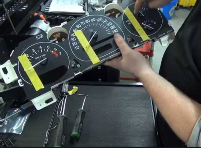
It may not come down to actually having to Replace The Instrument Panel Cluster in my 2000 Chevrolet Silverado 1500 Truck… But I want to be prepared early, should this contingency become necessary. I've observed several Black Vertical Lines obscuring the Square Orange LCD Screen of the 'Message Center' on my IPC Console and decided to order a replacement... Just In Case. The information covered in the below listed Video indicates the Odometer (VFD) Vacuum Fluorescent Display Tube for the PRNDL & Odometer vs. the Orange LCD Panel apparently share some surface mounted components and Printed Circuit Board routing in common that can force one or the other to fail as a result of problems within the IPC Logic Board. However... If the issue involves JUST the VFT "going dark"... THIS Video shows what to do to perform a Simple Re-Soldering Repair of the problem on the 1999-2002 GM-GMC Full Size Trucks and SUVs:


It follows on that if it becomes necessary to perform the IPC Swap… I DEFINITELY want to be able to Program The Odometer with my Current, Accurate Mileage ...which at present... is ridiculously low at under 74,000 Miles after 20 Long Years of modest use. I tried unsuccessfully to locate a Replacement LCD Orange Screen with NO LUCK and that problem lead me to the decision to pull the trigger and obtain a Replacement IPC instead.

The next issue has to do with the Actual Mileage Transfer Procedures that must be used to accurately convey the Odometer Reading from my Damaged IPC over to the Donor IPC. So far… What I have been able to come up with is quite thin on providing good information. I DO have a “GYMKO” Tech 2 and a Fully Functional TIS2000 Laptop capable of performing SPS and PASS-THRU activities.

But the Question remains whether or not the Tech 2 WILL perform this Task properly and NOT upset the Apple Cart if the PCM AND BCM also store the Identical Odometer Readings required for reconciliation after the Ignition Key is turned on. I will NOT install the Replacement IPC Unit until I've nailed this problem down. Any considered advice coming from Members having Hands On experience after successfully performing this Task will hold my gratitude... and my rapt attention. Thanks in Advance for this Assistance.

https://www.gmfullsize.com/threads/wtf-cant-program-mileage-into-cluster.127674/

From the above Link... But in reference to LATER Model GM Full Size Truck IPCs rather than the 1999-2002 GM-GMC versions:

TRANSFERODOMETERMILEAGE1.jpg

Attention: This bulletin applies to vehicles sold in the U.S. and Canada Only.
--------------------------------------------------------------------------------
This bulletin is being revised to add information for the 2009 model year and add new 2009 vehicles. Please discard Corporate Bulletin Number 07-08-49-020A (Section 08 -- Body & Accessories).
--------------------------------------------------------------------------------
The purpose of this bulletin is to provide a reference guide to help identify which season odometer programming method to use after replacing the Instrument Panel Cluster (IPC). The three season odometer programming methods in use today are listed below. In addition, this reference guide lists the component where the season odometer value is stored. The season odometer value may be stored in the IPC, the Driver Information Center (DIC), or the Integrated Body Control Module (IBCM), also commonly called a Body Control Module (BCM).

Season Odometer Programming Methods In Use Today
IPC reprogramming and setup using the Service Programming System (SPS).
Odometer setup at the Electronic Service Center (ESC) when using an exchange IPC/DIC.

Tech2® -- The Tech2 is used to setup a replacement BCM, which includes loading the odometer value that is displayed and stored in the IPC. A replacement IPC will display the previously stored vehicle odometer value, communicated from the BCM, after cycling the ignition or driving the vehicle.

Model
Model Year
Odometer Value Storage
Odometer Programming Method


I have NOT been able to confirm that what this covered within this Technical Bulletin will also apply to the 1999 through 2002 GMT800 Truck Line Series as well.

These are Screen Prints from a Youtube IPC-LCD SCreen Repair Video covering the 2000 Chevrolet Silverado 1500 and showing the "Locus In Quo":

F05ZUC7HKM94089.LARGE.jpgorangelcdpanel.jpgorangelcdpanelnumberbest.jpgorangelcdpanelnumberbest1.jpg

...and of course...Here is the Source Video for this information:

 
Last edited:

Alfa-Norway

Member
Mar 4, 2019
56
Norway
Another way is to get an Arduino Eeprom programmer that you can make yourself.
It's this fabulous guy who's behind it . He can be found on Youtube
If you want to make this project yourself the source code and gerber files are on this link https://github.com/garnerm91/st95020/tree/master/V2

I sent gerber files to https://jlcpcb.com/ and got 5 pcb`r sent after a few days.

I bought resistors, transistors on Mouser.com
5Pcs SOIC8 SOP8 Test Clip for EEPROM 93CXX / 25CXX / 24CXX In-circuit Programming + 2 Adapters and
Geekcreit® ATmega328P Nano V3 Controller Board Improved Version Module Development Board at Banggood.comDSC_0428.JPG
 
  • Like
Reactions: mrrsm

mrrsm

Original poster
Lifetime VIP Donor
Supporting Donor
Member
Oct 22, 2015
7,700
Tampa Bay Area
Wow Man... In the words of my Father's Native LanguageTUSSENTAKK.jpg Brother!!!

This will be a Whole New Ballgame for me... But I'll try to follow your Recipe for the Arduino Board and Component Purchases and Assembly. I'm hoping I can find the requisite Linux Apps similar to the ones the VOP (Video Original Poster) uses for Serial Communications and try to achieve the same success with something similar to what he has managed to cobble together. I'll need to understand all of the procedures that must be followed before I will give this idea a try. What I'll need are the complete details about these issues:

(1) All of the Software needed to communicate between the Laptop through the Arduino and into and out of my IPC Board (Which by the way... actually is IDENTICAL to the one he uses for the Odometer Update!

(2) All of the required equipment; cables, soldering gear...whatever... as his Work Bench looks like a "Bag of Snakes" and I can't figure out the "Ass, Heads or Tail " of what he has arranged for his Power Supply and Cabling.

(3) I'll need to understand the List of the Requisite Components and how to order them all. Iwant to be able to create the Arduino Board MYSELF,without having ANY company demand that I must order a certain number of fully assembled "bread boards" to get what I need and later put things together.

(4) I'll need Time... Enough in fact to be able to Learn and Practice with all of this Gear. I already have an Extra IPC from a 2000 Chevrolet Silverado 1500 to play with and another few Damaged Ones from eBay on the way. I just need to be able to SEE and Understand exactly how all of these things work together so as NOT to FUBAR the New IPC.

THIS Looks Very Promising for us Linux Mint Ver, 20 OS Users:


Alternatively, THIS also looks quite promising for setting up the Arduino Environment on Linux Mint:


Along with many other YouTube Arduino Training Videos:

 
Last edited:
  • Like
Reactions: Alfa-Norway

Alfa-Norway

Member
Mar 4, 2019
56
Norway
I use the Arduino software on my windows 10 pc and the HxD Hex Editor. Its fun to play with. I have two 2005 board to work on. The nice thing is that you can hook up the eeprom programmer without desoldering the Eeprom. If you see on my picture the power supply is from the usb on my computer.
 

Alfa-Norway

Member
Mar 4, 2019
56
Norway
Here are what i got in the mail after i sent gerber file to china for pcb.DSC_0415_b790dd57.JPG
And you need
R1 og R2 10 ohm 1/4w
R3 og R4 10k ohm 1/4w
Transitor 2n2222 and 2n5401
 
  • Like
Reactions: mrrsm

mrrsm

Original poster
Lifetime VIP Donor
Supporting Donor
Member
Oct 22, 2015
7,700
Tampa Bay Area
Thanks for the "Specs" update... But since I never do ANYTHING by Halves... (and I am SO Damned Anxious to try this "Stuff" out...) I just ordered the 'Whole Kit & Caboodle' off of Amazon. Do you think I'll have everything I'll need? This stuff will arrive tomorrow. :>)
ARDUINOGEAR.jpg
Also... I've installed wxHexEditor as compatible with Linux Mint Ver. 20:

Courtesy:

wxHexEditor: One of the Linux Hex Editors that has some advanced features and while there is no official documentation for the editor, there is a well written wiki page that provides explanation as to how to use the tool. The wiki page can be found here.


wxHexEditor.png
 
Last edited:
  • Like
Reactions: Alfa-Norway

Alfa-Norway

Member
Mar 4, 2019
56
Norway
The kit looks nice ! I is it Arduino nano in the kit ? I think you need that. But i am not an electronic expert. i am an old plummer and tig welder. :2thumbsup: Good luck with your prosject. Take care and stay safe.
 
  • Like
Reactions: mrrsm

Mooseman

Moderator
Dec 4, 2011
25,324
Ottawa, ON
This is certainly of interest to me as I have replaced my LS cluster with an LT with significantly higher mileage and would like to correct that.

Just one question: Will this work with ALL clusters or just the 00-02?
 
  • Like
Reactions: Alfa-Norway

Alfa-Norway

Member
Mar 4, 2019
56
Norway
It's a different way on a 00-02 than on 03 and up. As you can see on this youtube video:
You can use
the SOIC8 SOP8 Test Clip on the Eeprom on 2003 and up, on 00-02 you have to solder on some pin as you can see in the video.
 
Last edited:
  • Like
Reactions: mrrsm and Mooseman

mrrsm

Original poster
Lifetime VIP Donor
Supporting Donor
Member
Oct 22, 2015
7,700
Tampa Bay Area
Thanks @Alpha-Norway ... The issue I have right now with the IPC in my 2000 Chevrolet Silverado IPC is that the LED Message Center presents with Black Vertical Lines. Last year, I purchased a Re-Manned IPC from a reputable company with the intention to just Remove and Swap the Green Board from the Old IPC and Solder it onto the Re-Manned IPC. All of the Videos shown above have proven that this can work. The latest investigation of this matter shows that I am on the right track:

Y2KSILVERADOIPCPROBLEM.jpgFQ75K42HKM940M8.jpg

But ever since delving deeper into all of this, I see a a real opportunity to be able to Copy the Binary File off of my Old IPC and use either an Arduino Set-Up to Over-Write the Tiny Chips on the OTHER IPC Boards I have to experiment with by other methods as well. From prior experience with owning and using the MOATES BURN2 Chip to USB Interface, I think that I can just add in the proper Tiny Chip Adapter and be able to Read the Mini-BIN Chip directly to my Linux Mint Laptop using THIS Device:

moates-burn2-chip-programmer-14.jpg5580613900_0e52070635_z.jpg

This area is so fraught with Mystery and Misinformation that if nothing else, I'll be able to report with certainty that it can be done and done right by a Non-Genius, Average Mechanic. It is very encouraging to observe THIS VOP (Video Original Poster) showing the Two Best Techniques to Remove, Read, Modify the BIN if that is also necessary and then Re-Install these Tiny Chips right back onto their Green Boards:


Our main concern has always been that the whole setup could become "Bricked" after performing this task after becoming unable to reconcile any possible cross-checking Algorithm happening through the Body Control Module or also working through the PCM in some way that would invalidate the IPC. I'm hoping that creating a "Perfect Duplication" of the existing OEM IPC BIN File is the best way to do this. If I can Read and Save the OEM IPC BIN... then I'll be able to play around with Reading and Writing that same File under Bench Top conditions and NOT risk voiding the OEM IPC BIN.

I've taken the plunge already and ordered this equipment to expedite the De-soldering of the Green Board from the IPC presently installed in my 2000 Silverado IPC. But FIRST... I'll be Experimenting first with this technique of doing the R&R&W&R (Removing, Reading, Writing, Replacing) of the Tiny Chip upon a $20.00 IPC I have coming from eBay to practice with. I'll Photo-Document all of the steps I'll be using and Post them back on later addtitions.

Using THIS De-Soldering Gun will speed up the removal of the Green Board from the IPC:


DSOLDERINGUN3.jpgDSOLDERINGUN5.jpgDSOLDERINGUN4.jpg

This Hot Air Gun will help to focus enough heat on the Small Chips to "float" them off of the Green Boards and not damage the adjacent components:

WAGNERHOTAIRGUN.jpgWAGNERHOTAIRGUN2.jpgWAGNERHOTAIRGUN3.jpg

...and to be able to actually SEE close enough to work the Tiny Soldered Connections, THIS Very Inexpensive USB Microscope WILL work (Watch the VOP using it in the above Video)

https://www.amazon.com/dp/B06WD843ZM/?tag=gmtnation-20

MICROSCOPEUSB.jpgMICROSCOPEUSB1.jpg

I've also got a pair of Harness Connectors coming from eBay to use when hooking up my AC/DC Power Supply and the Tech 2 Scanner on the Bench to test out these IPCs, Before, During and After performing this Green Board Swap:

IPCHARNESS1.jpgIPCHARNESS.jpgIPCHARNESS3.jpgIPCHARNESS4.jpg

I'll be cross-checking whether or not THIS Pin-Out Information that seems meant for the GM Later Model IPCs are the SAME in order to make a working GM 1999-2000 Full Size Truck IPC Bench Test Harness:

GMCLUSTEREPAIR1.jpgGMCLUSTEREPAIR2.jpg
@Alpha-Norway ... Perhaps you can cross check this information and see if these Pin-Out References will work for the 99-02 IPCs ...just as written?
 
Last edited:
  • Like
Reactions: Alfa-Norway

Alfa-Norway

Member
Mar 4, 2019
56
Norway
Here are the Instrument Panel, Gages, Connector End Views on your model taken from gm parts and service information that i have on my pc. ipc 2000.jpg
I hope that help you. If its not right model you can send me vin # on a pm message and i will look it up.
 
Last edited:
  • Like
Reactions: mrrsm

mrrsm

Original poster
Lifetime VIP Donor
Supporting Donor
Member
Oct 22, 2015
7,700
Tampa Bay Area
Thanks, Brother... That Image is PRECISELY the One I needed!
 
  • Like
Reactions: Alfa-Norway

mrrsm

Original poster
Lifetime VIP Donor
Supporting Donor
Member
Oct 22, 2015
7,700
Tampa Bay Area
@Alfa-Norway ...I forgot to ask whether or not you have the Wire Diagram Schematic for that PCB you sent off for... or the flat and level images of the Front and Back of the PCB used to make that EEprom Progammer? It would help me with "Bread-Boarding" the components and for making same thing in the absence of having to order them or mess around with the "Gerber" issues. TIA.
 

mrrsm

Original poster
Lifetime VIP Donor
Supporting Donor
Member
Oct 22, 2015
7,700
Tampa Bay Area
"So Shines a Good Deed... Upon a Weary World..."

Thanks... This is AWESOME HELP ... and will make things so much easier for me!!!
 

mrrsm

Original poster
Lifetime VIP Donor
Supporting Donor
Member
Oct 22, 2015
7,700
Tampa Bay Area
Oh....MAN! I can't believe that you even rendered the Schematic in "Blue Print Blue"...Too! You are AMAZING, Dude!

Again... "Manga Takke Skal De Ha!" :2thumbsup:

Once I get my hands on your List of Components... I'll "Bread-Board" this device and get to work on the IPCs. THIS is proving to be a VERY Interesting Project that shows just How Robust the GMT Nation World Wide Community...REALLY Is. :ok:
 
  • Like
Reactions: Alfa-Norway

mrrsm

Original poster
Lifetime VIP Donor
Supporting Donor
Member
Oct 22, 2015
7,700
Tampa Bay Area
About the required Arduino Nano... In looking over your PCB ...you have the
ATmega328P variant versus the vs. the OEM Arduino Nano ATmega328 (A000005) that I have here. I looked over the Atmel PDF and was wondering whether their Pin-Outs are DIFFERENT, I've attached that Atmel PDF below

Please let me know if I need to make any connection adjustments to my Arduino Nano when I populate the Bread Board with all of the components. The Arduino Kit I have is only missing the 2N5401 Transistor, so I've ordered a Transistor Kit that has a 'Fist Full' of variations... including THAT one:
 

Attachments

  • Atmel-42559-Differences-between-ATmega328P-and-ATmega328PB_ApplicationNote_AT15007.pdf
    276.1 KB · Views: 8

mrrsm

Original poster
Lifetime VIP Donor
Supporting Donor
Member
Oct 22, 2015
7,700
Tampa Bay Area
No Problem... I've solved this issue by ordering a set of (3) LAFVIN Arduinos with an ATmega328P design plus the USB cables for around $14.00 with Free S&H from Amazon just now:


LAFVINARDUINO1.jpg
This way... I won't have to worry about any of these distinctions or whether or not the Arduino I'm using here is a "DBOM"*** to the One Soldered onto your PCB that has the identical ATmega328P Feature!

*** Dead Balls On Match

More Fun is coming later on... :>)
 
Last edited:
  • Like
Reactions: Alfa-Norway

mrrsm

Original poster
Lifetime VIP Donor
Supporting Donor
Member
Oct 22, 2015
7,700
Tampa Bay Area
If anyone is wondering (Why?) I would invest in a “Dedicated De-Soldering Gun”...Watch how these things work with Speed and Cleanliness and end up leaving a Neat, Conductive MOBO Surface to work with.

When trying to swap around components with as many as 65 Solder Contact Connectors, using a Gun like this will help Take out the Tedium and the Danger of applying Too Much HEAT that can often wind up Lifting or Tearing the Gold-Copper Foil Contact Pads and risk destroying the various Logic Boards Components being worked on.

Having something like THIS Gun when replacing a whole raft of Stepper-Motors and LEDs also makes Perfect Sense.


As much as I'm enjoying learning about this stuff... For anyone who just wants to:

(1) Get the Chip OFF of the IPC Green Board.
(2) Read and Save OEM Chip BIN on the Laptop.
(3) Make any required Hex Code Adjustments.
(4) Write the BIN back onto the Chip.
(5) Re-Solder the Chip Back onto the Green Board.
(6) NOT have to work with Creating an Arduino Set Up.
(7) NOT have to Learn Low Level Hexadecimal Coding...

THIS is THE Kit for you... $75.00 on Amazon:


ACEIRMCUSBPROGRAMMER0.jpgACEIRMCUSBPROGRAMMER1.jpgACEIRMCUSBPROGRAMMER2.jpgACEIRMCUSBPROGRAMMER3.jpgACEIRMCUSBPROGRAMMER4.jpgACEIRMCUSBPROGRAMMER5.jpgACEIRMCUSBPROGRAMMER6.jpg

Here is a Complete List of all the Chip Devices this Unit is capable of Reading From & Writing To:

http://www.xgecu.com/MiniPro/TL866II_List.txt

To Download and Preview the TL866II Software Micro-Controller SW::
(Choose Selection #2 as all Instructions are written in Mandarin Chinese)

http://forums.xgecu.com/viewthread.php?tid=20&page=1&extra=#pid23

THIS Video Shows How This Gear WORKS:


...and finally...for the Fine Soldering Work Station needed to get the components "Back On Board, THIS Video offers Comprehensive Suggestions for "How To Solder" and WHICH Gear is the Best to Use:


Last edited:
  • Like
Reactions: Alfa-Norway

mrrsm

Original poster
Lifetime VIP Donor
Supporting Donor
Member
Oct 22, 2015
7,700
Tampa Bay Area
Watch this Cool Video on how the VOP Technician R&Rd the MAC BIOS Chip using the TL866II Software Micro-Controller and was able to successfully Rescue a Frozen BIOS Chip in order to be able to access the MAC OS10 and power up the Machine... Like Nothing Bad Ever Happened.

After seeing this TL866II Software Micro-Controller in action... It occurs to me that in cases where the GMT-360 Members have no access to a Tech 2 or other High-End Scanner and either their Radios, their BCMs or their LGM Modules have ANY System Failures... Their on-board Chips and Important Contents could be Removed, Saved, Read and Over-Written to other Chips with Identical Part Numbers.

With this as an alternative approach, Damaged Radios, BCMs and LCMs could be replaced with either Brand New or Salvage Yard Units and then re-purposed back to their OEM Vehicle with the Original Identifying Information programmed inside... Like Nothing Bad EVER Happened... :>):

 
  • Like
Reactions: Alfa-Norway

mrrsm

Original poster
Lifetime VIP Donor
Supporting Donor
Member
Oct 22, 2015
7,700
Tampa Bay Area
I've been able to acquire enough Used IPC Hardware now not only to cobble together One Good IPC that will be Re-Programmed with the present Accurate Mileage of my In-Dwelling OEM IPC ... but also be able to Upgrade the IPC Features by adding in the quiescent, unfinished "Trans Temp" feature using this White Overlay from eBay @ $35.00 (the Blue version goes for $50.00):

http://rover.ebay.com/rover/1/711-5...0001&campid=5338077216&icep_item=324259221601

Everyone has their own ideas about what "Looks Good" on their IPC... but I've decided to try out using this contrasting White Background Gauge Faces to assist with Day Time Driving AND because I think they are an improvement over the 2000 OEM Jet Black Gauge Overlay that is Missing the Functional Trans-Temp IPC Gauge Feature.

WHITEDASHOVERLAY1.jpgBLUEDASHOVERLAY3.jpg

WHITEDASHOVERLAY2.jpgWHITEDASHOVERLAY4.jpgWHITEDASHOVERLAY3.jpg

We'll see how this idea pans out as I Photo Document the installation of the Integrated Circuit, Wire Extensions, Capacitors, Resistors and use an Extra "S" (Speedometer) Air Core Gauge that will be necessary to "Wake Up" the Dormant Trans Gauge Feature.
 
Last edited:
  • Like
Reactions: Mooseman

Mooseman

Moderator
Dec 4, 2011
25,324
Ottawa, ON
I kinda like the look of the white and had been searching for a Rainier cluster forever. Now you gave me the idea to look for overlays instead. My problem is finding one in Metric.
 
  • Like
Reactions: mrrsm

mrrsm

Original poster
Lifetime VIP Donor
Supporting Donor
Member
Oct 22, 2015
7,700
Tampa Bay Area
These on eBay are NOT a Metric IPC ...But they DO come from Buick Rainiers in Two Flavors:

*** New Listing***

2004 Buick Rainier White IPC:


WHITERAINIER1.jpgWHITERAINIER2.jpgWHITERAINIER3.jpg

2006 Buick Rainier Black IPC:


BLACKRANIER1.jpgBLACKRANIER2.jpgBLACKRANIER3.jpg
 

Mooseman

Moderator
Dec 4, 2011
25,324
Ottawa, ON
Found some however here's my dilemma. The Av is a US truck with the cluster in MPH but would like it in KPH but I do prefer the PSI instead of Kpa for oil and °F instead of °C for temp. Looking at the seller's FAQs, they do not recommend applying the KPH overlay over the MPH as it apparently is ugly when lit up showing ghosting under it. Possible solution would be to get a KPH cluster, swap the overlay and then apply the white face KPH overlay or just stay with a MPH and get its corresponding white overlay.

It's a cool idea but not a big priority for now.
 
  • Like
Reactions: Redbeard and mrrsm

mrrsm

Original poster
Lifetime VIP Donor
Supporting Donor
Member
Oct 22, 2015
7,700
Tampa Bay Area
Yeah... This is more LIKE what you need...just in reverse coloring... (God... How I DO like your idea about "Throat Punching GM Engineers...)


Too bad we don't have any CAD Geniuses around who could come up with a solution... ;>)

BESTGMKPHIPCOVERLAY.jpg
 
  • Like
Reactions: Redbeard

Alfa-Norway

Member
Mar 4, 2019
56
Norway
About the required Arduino Nano... In looking over your PCB ...you have the
ATmega328P variant versus the vs. the OEM Arduino Nano ATmega328 (A000005) that I have here. I looked over the Atmel PDF and was wondering whether their Pin-Outs are DIFFERENT, I've attached that Atmel PDF below

Please let me know if I need to make any connection adjustments to my Arduino Nano when I populate the Bread Board with all of the components. The Arduino Kit I have is only missing the 2N5401 Transistor, so I've ordered a Transistor Kit that has a 'Fist Full' of variations... including THAT one:

Update on Eeprom programmer. I had 4 extra pcb`s and bought 4 Arduino nano`s from china that would not read eeprom. Led bulbs, there are (4 pcs) of them, Led no. 4 marked l stood and flashed. Had to use old bootloader then it worked. For information only. ferdig programmer 2.JPG
 
  • Like
Reactions: mrrsm

mrrsm

Original poster
Lifetime VIP Donor
Supporting Donor
Member
Oct 22, 2015
7,700
Tampa Bay Area
Can you Jump-Solder-Copper Trace Wire to re-create some Fresh Breadboard connections leading from the PCB side of the Chip Clamp Plug interface to their origination points on the Board...and by-pass any of the possibly Bad Traces present on the PCB Flat Copper Traces? My understanding is that on SOME of the GM IPCs ...the Tiny EEPROM Chips cannot be read while surface mounted ...unless they are De-Soldered first and mounted into a proper Chip Holder for Reads and Writes.

I'd double check the Soldering on the Pins on the Board, too and Touch Up any solder that looks even Slightly Sketchy. Double Check your 8-Wire Flat Cable for anything that looks to have Cuts or Shorts, too. You just never know when these cables are made in huge batches. Likewise... go over all of your Surface Mounted Components with a Good Glass and touch up their Solder Points as well.


I've read that occasionally, some PCBs that are the less expensive "Non-OEM" Chinese House Brands DO have some manufacturing issues from time to time that can come in as "Bad Batches". So far though, I've spent a little more money to Buy the More Expensive Brand Name flavors of a few Full Size, Genuine Arduino Boards and I've also bought some Cheaper Chinese Arduino Nano PCBs that are still unsealed inside of tiny Anti-Static Baggies yet to be opened and tried out on a few Test Breadboard Builds.

I've also picked up a 2000-2002 Sierra-Silverado IPC Chip (Damn... These things are SO TINY!) that came pre-loaded with the Generic Factory EEPROM Program installed so I can mount it into a Breadboard Chip Holder and read the Program and then practice writing it over to a few others Chips.

I need the chance to get familiar with the Arduino IDE and XGPRO Software Suites before I start messing around with any of the in-dwelling soldered Chips on a few 2000-2002 Sierra-Silverado Instrument Panel Clusters I've got...waiting in the wings. (I'll photo Document all of that in a Separate Thread to avoid cluttering up yours).
 
Last edited:
  • Like
Reactions: Alfa-Norway

Alfa-Norway

Member
Mar 4, 2019
56
Norway
Some gm ipc especially 03-04 mod eeprom ( U15 ) sits close to the prnd321 display and are difficult to mount chip holder clips. at 05 and up eeprom has changed places.u16.jpg

I have seen someone who bends away the display a little too get the clip mounted but it is not recommended.
You must not have power on the panel when reading and writing to the eeprom
 
Last edited:
  • Like
Reactions: mrrsm

mrrsm

Original poster
Lifetime VIP Donor
Supporting Donor
Member
Oct 22, 2015
7,700
Tampa Bay Area
@Alfa-Norway I was doing a bit more research and tripped over THIS fascinating GM TSB #07-08-49-020E Advisory and Updated PDF that completely clears the air of which GM Products (listed Non-Alphabetically) by Years-Makes-Models herein require CERTAIN, specific methods for transferring Odometer Readings whenever installing any Replacement Instrument Panel Clusters or New Body Control Modules… or Both.

The basic instructions here wipe away any doubts I had about the utility of us performing the Physical R&R EEPROM Chip reading and writing procedures and perhaps then having to use SPS to ensure the Correct Odometer readings work properly and remain reconciled in all the right places. I have yet to test these procedures out “On the Bench” and now would be a good time to ask what you think needs to be done to get this right.

I know that @TJBaker57 has been working out investigating the PCM-BCM Diagnostics in a “Bench-Top” setting ...and since he is very familiar with using TIS2000 and the SPS feature for PCM and Modules Calibration Updates with his Tech 2, his input on this matter would also be very helpful and much appreciated:

https://testing-public.carmd.com/Tsb/Download/94387/07-08-49-020F_en_US

The other Question in consideration is "Do THESE Security Re-Learn Procedures STILL need to be done after this work is completed?" *Linked below*:


Even though these GM Models are not within our general scope and concern, this Document from NHTSA (MC-10137517-9999) notes the need to be aware that some of GM Product Lines WILL require Disconnecting the IPC prior to Re-Programming Newly Installed BCMs to avoid having the Wrong Odometer Readings transferred:
 

Attachments

  • 07-08-49-020F_en_US.pdf
    102.5 KB · Views: 9
  • MC-10137517-9999.pdf
    67.4 KB · Views: 9
Last edited:
  • Like
Reactions: Alfa-Norway

Forum Statistics

Threads
23,314
Posts
637,846
Members
18,520
Latest member
Firebaugh86

Members Online