- Jan 29, 2012
- 268
Tools needed: 7mm socket, pry bar, drill with 7/32 bit, soldering iron and solder, wire strippers, heat shrink tubing or electrical tape, dremel with sanding wheel. Might need other drll bits/utility knife to enlarge cutout in panel.
Parts needed: 2' or so of ethernet cable, 3.5mm socket (Radio Shack 274-246) $2.69
Love my new 9-7x, but the lack of aux input for iPod/MP3/phone is a bit annoying. I found the basic info for this on TV and a couple other sites, I thought I'd put it here as I did the project myself. Using this jack, the XM function is left intact. If you set your head unit to XM and plug in a 3.5mm device, it'll play the device and cut off the XM. If you unplug your device, the XM module is restored.
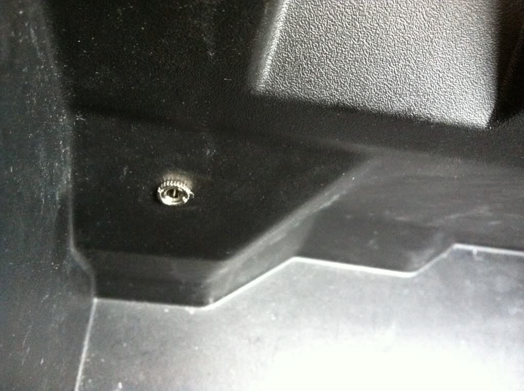
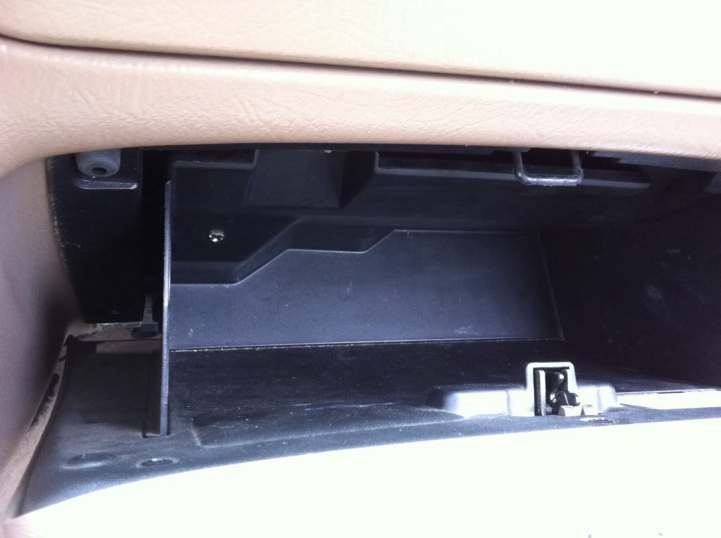
Started by removing 2 7mm screws from the panel below the glove box. It popped right out, the back side of it simply rests on a shelf.


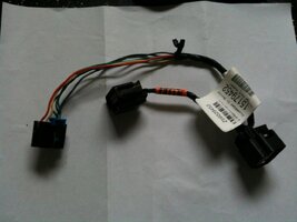
The XM module was mounted to this panel. It was convenient to remove the connector from the module to work on it. The wiring harness connects at the back of the module on the right. It had a blue 'safety' that I popped out (it stayed attached to the plug) before being able to remove it. It has a convenient connector right in front, made it easy to do the soldering on the bench.

One end of my ethernet cable got this jack. 5 wires needed here, one ground and two each for the audio left and right signals.


In the harness, you're looking for a brown/white, a green/white and a black/white (there are 2 black/white, you want the one from pin 9 on the XM side of the harness. I cut them somewhere towards the middle of the harness and stripped back enough insulation to get good soldering room. To keep it simple, I used the brown and green wires from the ethernet to match the audio wires, and used the solid blue for the ground. If you're smarter then me, solder both the blue and blue/white to the jack terminal, it'll make your soldering into the harness easier. If you decide to use shrink wrap to cover your connections, be REALLY sure to put the tube on before you start connecting wires. I'm proud/embarrassed to say that this is the first time I've remembered every one and didn't have to go back and redo a joint or two to add in the shrink tube.
On the Jack - Ethernet - XM Harness
Pin 1 - Ground - Blue and Blue/white - black/white 9 both ways
Pin 2 - Left Audio - Solid brown - brown/white towards radio
Pin 3 - Left Audio - brown/white - brown/white towards XM module
Pin 4 - Right Audio - green/white - green/white towards XM module
Pin 5 - Right Audio - solid green - green/white towards radio
I neglected to take a picture of the finished assembly before installation, but here's the installed version. The blue is my added in ethernet cable.

Now, the fun part was trying to get a good installation point for the jack. I found a great spot below on the panel surrounding the stereo and climate controls, but found that when I removed the panel there was no space behind it, solid plastic. First I confirmed my location had nothing behind it, and drilled a couple of holes that I connected with a small blade to give me the opening I needed. A 7/32 hole in the front panel was my mounting location.
I did have to use a dremel with a sanding wheel on the back of the panel as it was too think to push the jack through. Once installed, I used a dab of gorilla glue on the jack as well as the the included nut. I didn't want it to spin and damage my solder job.
Here's the installed photos - should help make sense of everything.


And the final product. Used it today, went back and forth between XM and iPod at will.


Parts needed: 2' or so of ethernet cable, 3.5mm socket (Radio Shack 274-246) $2.69
Love my new 9-7x, but the lack of aux input for iPod/MP3/phone is a bit annoying. I found the basic info for this on TV and a couple other sites, I thought I'd put it here as I did the project myself. Using this jack, the XM function is left intact. If you set your head unit to XM and plug in a 3.5mm device, it'll play the device and cut off the XM. If you unplug your device, the XM module is restored.
Started by removing 2 7mm screws from the panel below the glove box. It popped right out, the back side of it simply rests on a shelf.
The XM module was mounted to this panel. It was convenient to remove the connector from the module to work on it. The wiring harness connects at the back of the module on the right. It had a blue 'safety' that I popped out (it stayed attached to the plug) before being able to remove it. It has a convenient connector right in front, made it easy to do the soldering on the bench.
One end of my ethernet cable got this jack. 5 wires needed here, one ground and two each for the audio left and right signals.
In the harness, you're looking for a brown/white, a green/white and a black/white (there are 2 black/white, you want the one from pin 9 on the XM side of the harness. I cut them somewhere towards the middle of the harness and stripped back enough insulation to get good soldering room. To keep it simple, I used the brown and green wires from the ethernet to match the audio wires, and used the solid blue for the ground. If you're smarter then me, solder both the blue and blue/white to the jack terminal, it'll make your soldering into the harness easier. If you decide to use shrink wrap to cover your connections, be REALLY sure to put the tube on before you start connecting wires. I'm proud/embarrassed to say that this is the first time I've remembered every one and didn't have to go back and redo a joint or two to add in the shrink tube.
On the Jack - Ethernet - XM Harness
Pin 1 - Ground - Blue and Blue/white - black/white 9 both ways
Pin 2 - Left Audio - Solid brown - brown/white towards radio
Pin 3 - Left Audio - brown/white - brown/white towards XM module
Pin 4 - Right Audio - green/white - green/white towards XM module
Pin 5 - Right Audio - solid green - green/white towards radio
I neglected to take a picture of the finished assembly before installation, but here's the installed version. The blue is my added in ethernet cable.
Now, the fun part was trying to get a good installation point for the jack. I found a great spot below on the panel surrounding the stereo and climate controls, but found that when I removed the panel there was no space behind it, solid plastic. First I confirmed my location had nothing behind it, and drilled a couple of holes that I connected with a small blade to give me the opening I needed. A 7/32 hole in the front panel was my mounting location.
I did have to use a dremel with a sanding wheel on the back of the panel as it was too think to push the jack through. Once installed, I used a dab of gorilla glue on the jack as well as the the included nut. I didn't want it to spin and damage my solder job.
Here's the installed photos - should help make sense of everything.
And the final product. Used it today, went back and forth between XM and iPod at will.


 The only thing i can do if i wanna do this is to use liquid electrical tape leave all the connections