You are using an out of date browser. It may not display this or other websites correctly.
You should upgrade or use an alternative browser.
You should upgrade or use an alternative browser.
SOLVED! No Crank, No Start, Communication Codes Present
- Thread starter cope1980
- Start date

I have the BCM out, and the case open. I do not see anything obvious. All pins look secure and no broken solder connectionsIf you have a verified ground at A11, & B11, and power to the 5 hot at all times terminal we checked. And then apply power at terminal A18 (that comes from the ignition switch to ACC, RUN and Start) and there is still no 5 volts to the yellow Passlock wire then it is looking like a BCM fault. In this case it could be time to remove and inspect the BCM for obvious damage. The BCM case opens up real easy to inspect the circuit card.
I have the ribbon cable here on my desk, along with the BCM.I would inspect that ribbon cable really close. Maybe test for continuity at the power and ground traces.
I have tested each individual trace on both sides of the cable. All traces read continuity, with a reading of .1 ohms ( Lead test on my meter was the same.)
I have the ribbon cable here on my desk, along with the BCM.
I have tested each individual trace on both sides of the cable. All traces read continuity, with a reading of .1 ohms ( Lead test on my meter was the same.)
This is indeed a puzzle.
Lets review,
grounds at A11 & B11
12 volts at the orange wire, connector 1, terminal A3 (not ribbon cable)
12 volts hot at all times at ribbon cable A1/A2, B4, B13, B17
This should be enough for the BCM to answer the 'pings' we are sending to all modules on the data bus with the serial terminal app. Even with key OFF.
With key to ACC or greater there should be 12 volts at A18 of the ribbon cable.
This should send roughly 5 volts to the yellow wire running to your resistor pair.
I am trying to use the passlock voltage as proof of the BCM being alive. I cannot yet think of another way.
Should I check for the Passlock voltage at the BCM connector, instead of the resistor? Could the yellow wire be "broken" somewhere?
All things are possible I guess. We have covered the basics.
That particular yellow wire is not easily accessed at the BCM being behind a bunch.
There is another wire there that may be of use as a test. It is the red/white wire that supplies 12 volt power from the BCM to the electronic circuitry of the passlock sensor.
Looking at the same picture I posted with the serial data wires. See a pink a black and a red/white wire side by side on the upper connector? Check the red/white for 12 volts when key is not OFF.
I just did a continuity test on the yellow wire. It ohms out good from B10 on the small gray plug to the resistor. I will test red/white now.All things are possible I guess. We have covered the basics.
That particular yellow wire is not easily accessed at the BCM being behind a bunch.
There is another wire there that may be of use as a test. It is the red/white wire that supplies 12 volt power from the BCM to the electronic circuitry of the passlock sensor.
Looking at the same picture I posted with the serial data wires. See a pink a black and a red/white wire side by side on the upper connector? Check the red/white for 12 volts when key is not OFF.
Red/White wire, on #9 on Blue colored side of the upper plug has .1 vdc with key in run position
That would be E9 on connector #2. A 12 volt reference with key on.
Seen here:

If we have the powers and grounds correct and we get no output voltages on either of the yellow B10 or the Red/White E9 the evidence points to a failed BCM. Beyond that I haven't much to offer I'm afraid.
All I can suggest is to reverify what we have already tested as far as power and grounds. Double check everything.
Look for bad solder on the card?
I can add that one time, as a test just to see if it was possible, I swapped a same year junkyard BCM into my TrailBlazer. After a security relearn it worked but my factory radio locked and my sunroof didn't work. But it started and ran, windows, door locks etc were OK.
After the test I swapped back my original and the radio and sunroof worked OK again.
Yours being an XUV may be different?? @TollKeeper may know.
I suspected the BCM, but not knowing enough, suspect is all I could do alone.
As far as replacing BCM, the physical part of it is simple. Will I need to program or whatever?
I do know where a junk Envoy XUV is at in a salvage yard, I'm pretty sure it is the same year.
As far as replacing BCM, the physical part of it is simple. Will I need to program or whatever?
I do know where a junk Envoy XUV is at in a salvage yard, I'm pretty sure it is the same year.
Mooseman
Moderator
Definitely the XUV has some very different programming. If you can secure an XUV BCM, it should work unless there is a difference in options like a sunroof or auto HVAC. However, it should be programmable with the proper software for your options and VIN. It would require a Tech 2 with a computer with Tis2000 or get a dealer to do it with the BCM alone on the bench with their equipment. You'll still need the 30 minute security relearn when you put it in.
You can just plug it in as-is just to see if it will work first.
You can just plug it in as-is just to see if it will work first.
Thank you guys for the information. And thanks to TJBaker57 for spending his evening messing with this.
I'll call the salvage yard in the morning and make sure it is still there before the 70 mile round trip.
We were able to borrow a car this evening, so that helps.
I'll call the salvage yard in the morning and make sure it is still there before the 70 mile round trip.
We were able to borrow a car this evening, so that helps.
15114669
Mooseman
Moderator
This site seems to think only 2004 2005...15114669

15114669 BCM - PLUG & PLAY | GM | BCU BCM Body Control Module OEM - Module Mechanics
Refurbished BCM | VIN Programming Included! Compatible: 2004 , 2005 GM OEM Part Number: 15114669 (See description below for more details)
lots of good stuff... I haven't read thru everything at this point so sorry if this was covered. Did you check that 5v ref is getting to the BCM. IF I recall some things in this area (ie. 5v), the electric fan clutch can cause issues with the 5v side of things which might have made their way here although it might be a stretch since it doesn't appear that comms with the bcm is not happening. Anyway, just throwing it out there.
15114669
I am one of those who just cannot let go of a puzzle.
Yesterday as we tested the BCM we checked all of the "hot at all times" 12 volt connections to the BCM.
At the time I did not know if all of these were necessary for the BCM to wake up. I was just duplicating the wiring diagram. This bothered me overnight so first thing this morning I set about determining the bare minumum for the BCM to come alive.
Turns out that that simply supplying 12 volts to connector 1 terminal A3 (smaller grey) and ground to ribbon cable A11 (or B11 as these are internally joined on the circuit card) is sufficient.
With no other connectors or connections when I supply this 12 volts to a BCM on the table I hear relays click inside and I have power at the 12 volt ref Passlock power terminal at connector 2 terminal E9, the red/white wire as well as the nominal 5 volt output from the BCM for the Passlock signal, yellow wire at connector 1 terminal B10.
I suspect that having power present for the Passlock system as described above is some form of fallback state meant to come into play where other wiring is at fault since under normal circumstances the Passlock is unpowered until the key is moved from OFF to any other state.
For communications in this state if I ping the BCM a couple of times I get replies though often not for the first ping. So comms are possible though the power mode state is sleep.
If I connect power to ribbon terminal A18 simulating key to ACC then there is a flurry of serial data as the BCM sets the power mode to some awake level and other modules on the serial data bus come online.
So if the primary power supply for the BCM is terminal A3 of connector 1 then if one cared to investigate that circuit for a fault here is what I measured for resistance across A1 to B1 with the BCM totally isolated, no other connections.
Red test lead to A3 connector 1, Black lead to ribbon cable A11 = 175.2k
Black test lead to A3 connector 1, red to ribbon cable A11 = 69.2k
Last edited:
It's probably a Good Idea to take a big step back for a moment ...and look at things from a "First Principles" point of view:
(1) While using a Bright Flashlight and while wearing a pair of MIL11 Nitrile Glove and an N-95 Face Mask along with Eye Protection... Examine EVERYTHING under the hood for ANY signs of Rodent Feeding (Chewed Chicken Bones, etc) along with Nesting Materials (pulled down headliner, pine needles stuffed under the Air Plenum and in the corners of the engine compartment) and the possible presence of Rodent Droppings and Urine Staining along with Chewed Wiring and Destroyed Plastic Harnessing and Connectors:


To prevent accidental exposure (and DEATH) due to the Dreaded HANTA Virus carried by Rodents, Follow ALL of the Cautions well desrcibed in THIS Link:
 gmtnation.com
(2) Anytime you have so many Inexplicable UXXXXX Codes in concert with sudden No Start-No Crank and No Run situations... Follow the EXCELLENT Instructions completely covered by Will Robinson's Classic OBD2 Diagnostic Video by taking down the the Vehicle Network at the two Network Splice Packs and after getting ALL of the Modules Off Line... Bring them back On Line One At A Time. Watch, Download and SAVE this Video for future reference and long term instruction value:
(1) While using a Bright Flashlight and while wearing a pair of MIL11 Nitrile Glove and an N-95 Face Mask along with Eye Protection... Examine EVERYTHING under the hood for ANY signs of Rodent Feeding (Chewed Chicken Bones, etc) along with Nesting Materials (pulled down headliner, pine needles stuffed under the Air Plenum and in the corners of the engine compartment) and the possible presence of Rodent Droppings and Urine Staining along with Chewed Wiring and Destroyed Plastic Harnessing and Connectors:
To prevent accidental exposure (and DEATH) due to the Dreaded HANTA Virus carried by Rodents, Follow ALL of the Cautions well desrcibed in THIS Link:
Under-Hood Vermin Infestation Issues
An off shoot of the many problems that the COVID-19 Corona Virus Pandemic brought along is the fact that many of our vehicles… NOT just the GMT-360s and GMT-400-800 Vehicles have had to be parked for longer than ordinary time frames. For some of us, depending upon the region of the countries...
(2) Anytime you have so many Inexplicable UXXXXX Codes in concert with sudden No Start-No Crank and No Run situations... Follow the EXCELLENT Instructions completely covered by Will Robinson's Classic OBD2 Diagnostic Video by taking down the the Vehicle Network at the two Network Splice Packs and after getting ALL of the Modules Off Line... Bring them back On Line One At A Time. Watch, Download and SAVE this Video for future reference and long term instruction value:
Last edited:
BUT with your everything "disconnected test", it leaves out possible issues with connections causing a "load" on something which may result in low / no voltages of things. Hopefully, the OP can do a similar setup maybe...  to see if the BCM comes alive at least in terms of "noises".... or can just get another BCM .
to see if the BCM comes alive at least in terms of "noises".... or can just get another BCM . BUT with your everything "disconnected test", it leaves out possible issues with connections causing a "load" on something which may result in low / no voltages of things. Hopefully, the OP can do a similar setup maybe...
That exact thought had crossed my mind. The OP had stated there was a measured 12 volts at the main BCM power input, connector 1 terminal A3. Each 12 volt "hot at all times" line has its' own 10 amp fuse.
If there were a high enough load would (A) the measured voltage at the input display a dropped voltage? And (B) would not such load blow a fuse?
My next step is to perform a current draw test on a desktop BCM hooked up as I did for the bare minimum to establish a baseline of sorts.
My next step is to perform a current draw test on a desktop BCM hooked up as I did for the bare minimum to establish a baseline of sorts.
Milliamps. We are talking about milliamps draw on the main BCM 12 volt feed. 90 some odd milliamps at first powerup. Depending on power mode state that drops to maybe 40 someodd milliamps. Left alone long enough and it goes to some sort of standby sleep mode at a mere 1.25 milliamps.
BUT.... you are looking at the 12v stuff.... but a "load", not necessarily a short could cause issue with the 5v area depending on what "shares" that source.
BUT... it is good that you measure the current as potentially that "reference point" may be easy for the OP to gather at his end.
you are looking at the 12v stuff.... but a "load", not necessarily a short could cause issue with the 5v area depending on what "shares" that source.BUT... it is good that you measure the current as potentially that "reference point" may be easy for the OP to gather at his end.
Ecmbuster
Member
Codes:
B0780 Control Unit 1A = Four Wheel Drive Low Range Indicator Circuit
B0775 Control Unit 1A = Four Wheel Drive High Range Indicator Circuit
B0770 Control Unit 1A = All Wheel Drive Indicator Circuit.
U1000 Control Unit 1A = Loss of Class 2 Serial Communications
U1064 Control Unit 1A = Lost Communication with Body Control Module
U1041 Control Unit 1A = Loss of Communication with Brake Module
U1000 Control Unit 58 = Loss of Class 2 Serial Communications
U1064 Control Unit 10 = Lost Communication with Body Control Module
It can take 1 (one) class 2 controller to take a class 2 network off-line
These tools:
uIsolate

 www.aeswave.com
Either purchased or hand made, can test the network and find the offending controller
www.aeswave.com
Either purchased or hand made, can test the network and find the offending controller
Read: U1064

 obd2pros.com
A simple / inexpensive not totally effective tool that tests the controllers the application has access to.
Within that simple tool, each mentioned controller can be tested for the reoccurring faults.
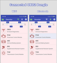
Chevrosys Pro

 play.google.com
Class 2 data description - Facts matter.
If all the B+ and B- are tested and prove OK with the the Class 2 data with an oscilloscope, the BCM is defective.
If multiple controllers record U1000, U1064, etc. (Lost Communication with Body Control Module) the BCM is defective.
If the BCM requires replacement, extra programming is required for the added accessories built within the vehicle.
A GM subscription is required:
The MDI 2 or J2534-2 device is required.
A defective BCM includes:
No Start, No crank
No LED or activity for transmission display on IC (P R N D L)
No dash illumination
No fuel gauge operation
No window operation
No door lock operation
Multiple network faults with multiple controllers
Inoperative / uncooperative controllers
The choice can be an OEM, rebuilt or used controller.
Been stung too many times and prefer OEM.
OBD II is not going to solve or diagnose the communication(s) issue.
Tools that work are: Tech2Win, GDS 2, Snap-On, Autel, Launch or any tool that has access to the Class 2 network is the best option.
B0780 Control Unit 1A = Four Wheel Drive Low Range Indicator Circuit
B0775 Control Unit 1A = Four Wheel Drive High Range Indicator Circuit
B0770 Control Unit 1A = All Wheel Drive Indicator Circuit.
U1000 Control Unit 1A = Loss of Class 2 Serial Communications
U1064 Control Unit 1A = Lost Communication with Body Control Module
U1041 Control Unit 1A = Loss of Communication with Brake Module
U1000 Control Unit 58 = Loss of Class 2 Serial Communications
U1064 Control Unit 10 = Lost Communication with Body Control Module
It can take 1 (one) class 2 controller to take a class 2 network off-line
These tools:
uIsolate
uIsolate Network Isolator
Use the uIsolate Network Isolator to find faulty modules in vehicle communication networks such as GM Class 2, CAN BUS, and other 1-wire and 2-wire networks.
www.aeswave.com
Read: U1064
U1064 – What Does It Mean and How To Fix It - OBD2PROS
This is one of the most frequent OBD2 trouble codes. Read the full article below to know what it means, how to fix it, and what other codes may show
A simple / inexpensive not totally effective tool that tests the controllers the application has access to.
Within that simple tool, each mentioned controller can be tested for the reoccurring faults.
Chevrosys Pro
ChevroSys Scan Pro - Apps on Google Play
Read & Clear Trouble Codes: Chevrolet Vehicle (Engine, ABS, SRS, TCM)
Class 2 data description - Facts matter.
If all the B+ and B- are tested and prove OK with the the Class 2 data with an oscilloscope, the BCM is defective.
If multiple controllers record U1000, U1064, etc. (Lost Communication with Body Control Module) the BCM is defective.
If the BCM requires replacement, extra programming is required for the added accessories built within the vehicle.
A GM subscription is required:
The MDI 2 or J2534-2 device is required.
A defective BCM includes:
No Start, No crank
No LED or activity for transmission display on IC (P R N D L)
No dash illumination
No fuel gauge operation
No window operation
No door lock operation
Multiple network faults with multiple controllers
Inoperative / uncooperative controllers
The choice can be an OEM, rebuilt or used controller.
Been stung too many times and prefer OEM.
OBD II is not going to solve or diagnose the communication(s) issue.
Tools that work are: Tech2Win, GDS 2, Snap-On, Autel, Launch or any tool that has access to the Class 2 network is the best option.
Attachments
"A few days ago, I got in to start the car, and no crank. The display read "UNKNOWN DRIVER" and "TAILGATE AJAR"...."
Might be worth examining the Boot-Grommet in between the Upper Roof Line and the Tail Gate for damage (Work -Hardened Wire Breaks) in the Harnessing servicing the LGM and the Tailgate-Windshield Wiper set up as any Module not communicationg properly on the Class 2 Network can bring down the entire system:
gmtnation.com
Might be worth examining the Boot-Grommet in between the Upper Roof Line and the Tail Gate for damage (Work -Hardened Wire Breaks) in the Harnessing servicing the LGM and the Tailgate-Windshield Wiper set up as any Module not communicationg properly on the Class 2 Network can bring down the entire system:
SOLVED! - Replaced liftgate - now electrical problems
Hello, I have a 2003 TB LTZ. The liftgate was rotting in the usual spots, only had 4 lines for the defroster work, and would not lock/unlock. I found a nice liftgate from a 2006 TB LT. While I was disconnecting the electrical connector, I could hear the lock for the liftgate making noise as I...
BUT....
BUT... it is good that you measure the current as potentially that "reference point" may be easy for the OP to gather at his end.
What specific 5 volt area are you speaking of here?? I know of only 2 in the BCM. One is for the rotary dimmer adjustment in the headlamp switch and the second is for the Passlock sensor signal. We tested the Passlock sensor 5 volt terminal but found that dead.
Testing a BCM seems to at the least suggest these two 5 volt source are not shared as there is about 14k resistance between the two.
Codes:
B0780 Control Unit 1A = Four Wheel Drive Low Range Indicator Circuit
B0775 Control Unit 1A = Four Wheel Drive High Range Indicator Circuit
B0770 Control Unit 1A = All Wheel Drive Indicator Circuit.
U1000 Control Unit 1A = Loss of Class 2 Serial Communications
U1064 Control Unit 1A = Lost Communication with Body Control Module
U1041 Control Unit 1A = Loss of Communication with Brake Module
U1000 Control Unit 58 = Loss of Class 2 Serial Communications
U1064 Control Unit 10 = Lost Communication with Body Control Module
It can take 1 (one) class 2 controller to take a class 2 network off-line
These tools:
uIsolate
Either purchased or hand made, can test the network and find the offending controlleruIsolate Network Isolator
Use the uIsolate Network Isolator to find faulty modules in vehicle communication networks such as GM Class 2, CAN BUS, and other 1-wire and 2-wire networks.
Read: U1064
U1064 – What Does It Mean and How To Fix It - OBD2PROS
This is one of the most frequent OBD2 trouble codes. Read the full article below to know what it means, how to fix it, and what other codes may show
A simple / inexpensive not totally effective tool that tests the controllers the application has access to.
Within that simple tool, each mentioned controller can be tested for the reoccurring faults.
Chevrosys Pro
ChevroSys Scan Pro - Apps on Google Play
Read & Clear Trouble Codes: Chevrolet Vehicle (Engine, ABS, SRS, TCM)
Class 2 data description - Facts matter.
If all the B+ and B- are tested and prove OK with the the Class 2 data with an oscilloscope, the BCM is defective.
If multiple controllers record U1000, U1064, etc. (Lost Communication with Body Control Module) the BCM is defective.
If the BCM requires replacement, extra programming is required for the added accessories built within the vehicle.
A GM subscription is required:
The MDI 2 or J2534-2 device is required.
A defective BCM includes:
No Start, No crank
No LED or activity for transmission display on IC (P R N D L)
No dash illumination
No fuel gauge operation
No window operation
No door lock operation
Multiple network faults with multiple controllers
Inoperative / uncooperative controllers
The choice can be an OEM, rebuilt or used controller.
Been stung too many times and prefer OEM.
OBD II is not going to solve or diagnose the communication(s) issue.
Tools that work are: Tech2Win, GDS 2, Snap-On, Autel, Launch or any tool that has access to the Class 2 network is the best option.
We already proved the serial data network is NOT down but is functioning normally. This is seen in messages 11 and 12.
This will not be readily evident to those who do not know how to read class 2 J1850 messages.
OK... did know they weren't tied together. Has he at least checked the other? Even if they aren't tied to cause a "loading" issue... maybe there regulator source isn't there for either as in "common track".What specific 5 volt area are you speaking of here?? I know of only 2 in the BCM. One is for the rotary dimmer adjustment in the headlamp switch and the second is for the Passlock sensor signal. We tested the Passlock sensor 5 volt terminal but found that dead.
Testing a BCM seems to at the least suggest these two 5 volt source are not shared as there is about 14k resistance between the two.
I apologize for not checking back, for some reason I didn't get notifications. I was unable to get the salvage yard BCM (someone already took it). I ordered one from eBay and it should be here Tuesday 9/5/23. I can do more tests tonight.
Update to my issues:
Used eBay BCM arrived today. I installed it and ran the AT's and the 20's. AT's all respond "OK" and I now show "40" in the 3rd byte. I am currently working on the security relearn.
Dome lights are working, windows and door locks are working. Radio is locked.
Used eBay BCM arrived today. I installed it and ran the AT's and the 20's. AT's all respond "OK" and I now show "40" in the 3rd byte. I am currently working on the security relearn.
Dome lights are working, windows and door locks are working. Radio is locked.
Update:
Security relearn successful. Car starts and runs. I do have a SERVICE AIR BAG message and the radio is locked. Everything else appears to be working.
Yay! So way back in post #1 you had a code from control unit 58 about a loss of communications. Is this code still present? Comtrol unit 58 is your airbags sometimes called the SIR module or even SIRS module.
Radio being locked must be expected for a replaced BCM. Both the radio and the BCM have the VIN number in them. If they don't match the radio locks. It is an anti-theft measure.
Original codes still present:
B0780 1A
B0775 1A
B0770 1A
U1000 1A
U1064 1A
These are all from the 4wd system, the TCCM is module 1A. First 3 are for indicator light circuits and the next 2 are communications loss codes.
Original codes now gone:
U1064 10
U1000 58
More communications loss codes.
New codes:
U1000 40
B3811 40
B3031 40
B2960 40
B2930 40
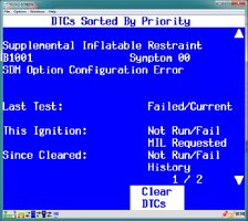
U1064 58
B1001 58
The first, U1000 is a communications code.
B3811 is rear washer circuit.
B3031, B2960, and B2930 are all related to the security system, is that resistor still in place? That "might" be related, not sure about that though.
The last 2 codes are from the SIR module. U1064 is the SIR has lost communications with the BCM and the B1001 is "Option configuration error" which is not surprising given the BCM is from a different vehicle.
Ecmbuster
Member
1) Read my earlier post.
2) Program the replacement BCM with the correct firmware via subscription.
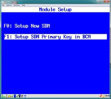
3) With a decent Bi-directional scan tool, reset the "SDM Primary Key"
4) Clear all faults.
5) Trash the resistor.
2) Program the replacement BCM with the correct firmware via subscription.
3) With a decent Bi-directional scan tool, reset the "SDM Primary Key"
4) Clear all faults.
5) Trash the resistor.
Attachments
Yes the resistor is still in place. I assume that code is due to a resistance change from the original in the "new" BCM?
The resistance that determines the Passlock signal voltage is actually inside the passlock sensor which is built into the ignition lock housing. No way to access without breaking the assembly. And other than exploration there is no need to get into the passlock sensor.
The BCM just stores the expected signal voltage value. A relearn allows the BCM to learn a new value for the signal voltage.
The sensor looks like this...
sensor in ignition housing...

Sensor removed from junkyard truck...

Sensor circuit itself. The actual resistor that varies between vehicles is circled here. I think there are maybe 12 variations? I have 4 or 5 in my test corral.

Update:
I apologize for the delay, life happened.
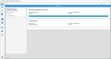
Went to the dealer and had the BCM flashed. Everything is working properly now. There are no service lights illuminated.
I do have a few codes still pending
TCCM codes, I tried the 4WD and everything operates, including the indicator lights. I also tried the Serial Terminal and the 1A is displayed in the 3rd Byte.
B0780 1A
B0775 1A
B0770 1A
U1000 1A
U1064 1A
Airbag Codes, no airbag message and 58 also shows up in Serial Terminal 3rd Byte
U1064 58
U1041 58
U1000 58
B1001 58
I apologize for the delay, life happened.
Went to the dealer and had the BCM flashed. Everything is working properly now. There are no service lights illuminated.
I do have a few codes still pending
TCCM codes, I tried the 4WD and everything operates, including the indicator lights. I also tried the Serial Terminal and the 1A is displayed in the 3rd Byte.
B0780 1A
B0775 1A
B0770 1A
U1000 1A
U1064 1A
Airbag Codes, no airbag message and 58 also shows up in Serial Terminal 3rd Byte
U1064 58
U1041 58
U1000 58
B1001 58
My B1001 58 code on Car Scanner description says "Option Configuration Error: Option Configuration Special Memory Malfunction: Option Configuration Variant Not Programmed; Option Configuration Calibration Not Learned"
I did find this information. Is it possible that the tech overlooked this when flashing the BCM?
Code B1001 GMC Description The Inflatable Restraint Sensing and Diagnostic Module (SDM) stores the vehicle's restraint ID from the Vehicle Identification Number (VIN) and the last 4 digits of the SDM part number. When the ignition is turned ON, the SDM compares this information to the information stored in the Body Control Module (BCM) over the General Motors Local Area Network (GMLAN) communication circuit. If there is a mismatch between the information stored in the SDM and BCM, Diagnostic Trouble Code (DTC) B1001 will be set.
Read more: https://www.autocodes.com/b1001_gmc.html
If you are not the original owner... perhaps running a CARFAX would reveal:
(1) Any Automotive Collisions (Especially from the Driver's Door Line forward)
(2) Whether or not the Vehicle has ever been driven in NA Geography that is Flood Prone.
(1) Any Automotive Collisions (Especially from the Driver's Door Line forward)
(2) Whether or not the Vehicle has ever been driven in NA Geography that is Flood Prone.
Last edited: