Pictorial Overview:

 www.flickr.com
Part 1 of 3 Parts:
Abstract:
This is a Repair Guide for using a Modified Technique vs. the Classic“The TIME-SERT Method” to more precisely install (14) M10 X 1.50 X 40MM Threaded Steel Cylinders inside all of the Crank-Shaft Mains Cap Screw Fastener Holes inside of the GM Atlas 4.2L LL8 Aluminum Engine Block:

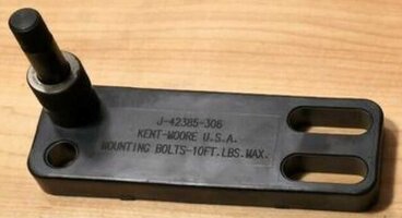
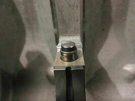
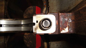
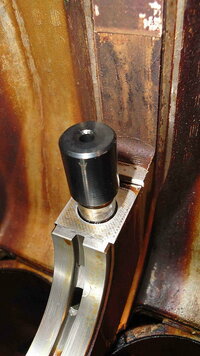
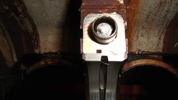
Image Information: This is what the Properly Set Up Aluminum Guide Plate should look like EACH AND EVERY TIME you Prepare to Drill Down into the Engine Block Mains to remove the Old Thread Lines in preparation for later using the TIME-SERT EXTRA LONG SI TAP, EXTRA LONG INSERT TOOL AND THE (14) M10 X 1.50 X 40MM INSERTS WITH RED THREAD LOCKER ON THE OUTER THREADS AND TIME-SERT OIL ON THE INSERT EXTRA-LONG INSERT HOLDER TOOL.
Take Note of the need to use an Accurate Machinist's Accurate 90 Degree Angle Square Gauge to ensure that the 12" X 13/32" Cobalt Drill is aligned to be as STRAIGHT AND TRUE as possible (at the N-E-W-S Positions ) Prior to Drilling Down in VERY Small Increments and with FREQUENT Bolt Hole Clean Outs using Canned Air and Re-Applying Cutting Oil or TRUE-TAP LUBRICANT.

This Article covers the procedures for repairing damaged Crankshaft Main Caps Threaded Bolt Holes in their Engines in the GM 4, 5 & 6 Cylinder Atlas - Vortec Aluminum Engine Blocks.
Block Preparation of the Work Area adjacent to the Crankshaft Mains Bolts Holes:

All Bock Prep Imagery can be seen HERE:
 www.flickr.com
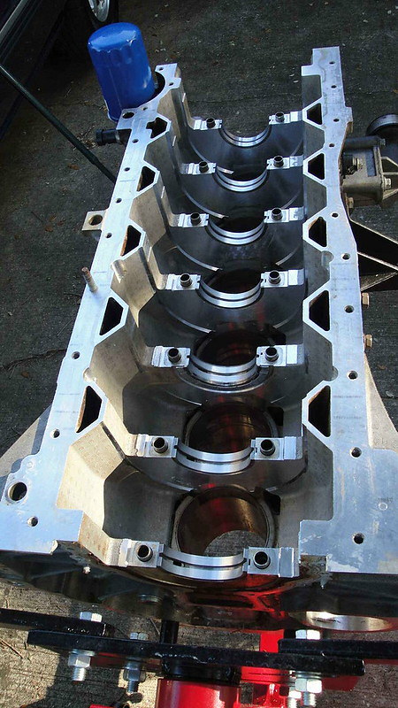
The All Aluminum Atlas Vortec 4200 LL8 Engine Block ‘rectangular box’ design affords the opportunity of having much free and open access once disassembled and is fairly easy to work on once the Engine gets stripped down and the motor has been scrupulously Cleaned, De-Greased and De-Carbonized. For this work to become worthwhile, before proceeding, the Engine Block MUST also be examined thoroughly for any Cracks in the Block and Mains Webbing Buttresses can be discovered.
Doing this clean up work will prevent investing time, energy and money on a “Fool’s Errand”. Having a Clean Block also reduces the chances of contaminating the pending TIME-SERT repair work areas and avoid the problem of NOT achieving the desired results. Working in this area of any Motor is NOT a Trivial Matter as “Good Surgeons Do NOT perform Operations under Septic Conditions” ...and neither should Good Mechanics during Engine Re-Building.
Cover and Isolate ALL non-involved areas within and without these procedures using a combination of Blue Painter’s Tape and sections of Clear Saran Wrap. By taking these precautions, working on Only One Specific Bolt Hole at a Time will allow it to receive the concentrated attentions and efforts to do everything correctly. This thoughtful approach will minimize the chances of Cross-Contaminating other areas inside of the Engine with Metal Dross, Sprue, Shards, Oily Chips or Debris that can get blown around with “Canned Air” and drop down inside of the myriad holes, nooks and crannies inside of the engine, only to wreak havoc later on:


The Saran Wrap has a nice “clingy” nature to it so that gathering up sections laden with these contaminants becomes a a simple process: Just Unseal the Tape and work from the Outer Edges by rolling up the Debris inwards, thereby trapping the various particles and shards within for easy disposal. Re-Apply more protective layers of the Saran Wrap and Blue Painter’s Tape as needed.
Best Mechanical Practices and Specialty Tool Requirements:
Start a Repair Journal and Document EVERYTHING You will Need to Remember and Follow as Orders of Operations all along the way.The Mechanic should acquire ALL of the Specialty Tools and Necessary Materials well in advance of beginning the work.
The important things to remember is that you will be trying to perfect this repair ONE BOLT HOLE AT A TIME... the Goal is to be able to carefully Accurately Repeat Each Procedure over and over for ALL (14) Bolt Holes following on with the same consistency and perfection of technique from Start to Finish.
You Do NOT have to BE a Machinist to respect the many ways and means most Machinists follow when performing their work in the narrow context here of using this Modified TIME-SERT System:


Download and Repeatedly Study and Review the various TIME-SERT Factory Instructional PDF(s). Also, Download, SAVE and WATCH all of the TIME-SERT “How To” Videos available on YouTube. Use these handy sources of information to prepare and educate yourself well in advance of doing ANYTHING to that Aluminum Engine Block. THIS IS THE KEY TO YOUR SUCCESSFUL REPAIR!
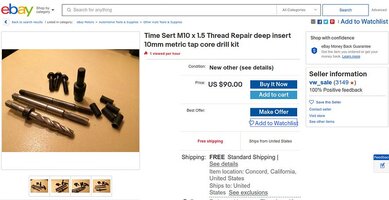
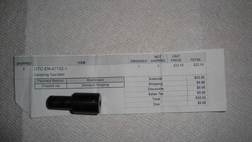
Identify ALL of the Specialty Tools covered within this Article and carefully search for them at the Best Possible Prices and Offers on eBay and Amazon. In many cases… YOU WILL have to Open Your Wallet and pay dearly for some of these Tools. However, I am including some ideas here that will help you to SAVE MONEY by “Mixing and Matching” Tools from Different, VERY ‘Pricey’ Kits.
You will appreciate being able to obtain either seldom-used Tools or Partial Kits individually from AND by choosing Alternative Tools that WILL offer you the same results ...but NOT at the ridiculously over-priced costs of Buying Complete Kits. Nothing worth doing is ever easy… so if you really want to do this work… you WILL have to invest much time and effort to gather the Right Tools for this Job.
Obtain additional sacrificial materials and a few extra GM OEM TTY Fasteners along with some ALUMINUM BLOCKS to practice with the machining and re-work via the Drilling and Tapping Tools. Then perform the TIME-SERT Insert Installation and TTY Bolt Tightening Procedures.
Follow the GM Factory Installation Guidelines and OEM Service Manual here at GMT Nation well on your Test Materials well in advance of doing the actual work on and inside of your Engine. YOU are completely responsible for the success or failure as the possible outcomes to this time, effort and expense. So it will be well worth your time to know Why, When, What and How to Use these necessary “Destroy...Then… Create” Machining and Metal Working Procedures so you can learn and understand that they CAN safely be done to benefit your particular Motor… FOR REAL.
More to Follow...
TIME-SERT
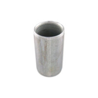
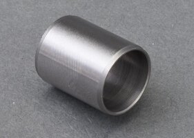
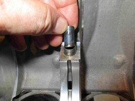
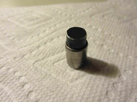
This Album contains images of the TIME-SERT M10 X 1.50 Installation Kit that includes the SERTS for Repairing M10 X 1.50 Thread Repair or UPGRADE of the GM 4.2L LL8 Engine Crankshaft Cradle Bolt Holes. The "2001: A Space Odyssey Monolith" Block of Heavy Black Steel will be used to Stabilize...
www.flickr.com
Part 1 of 3 Parts:
Abstract:
This is a Repair Guide for using a Modified Technique vs. the Classic“The TIME-SERT Method” to more precisely install (14) M10 X 1.50 X 40MM Threaded Steel Cylinders inside all of the Crank-Shaft Mains Cap Screw Fastener Holes inside of the GM Atlas 4.2L LL8 Aluminum Engine Block:
Image Information: This is what the Properly Set Up Aluminum Guide Plate should look like EACH AND EVERY TIME you Prepare to Drill Down into the Engine Block Mains to remove the Old Thread Lines in preparation for later using the TIME-SERT EXTRA LONG SI TAP, EXTRA LONG INSERT TOOL AND THE (14) M10 X 1.50 X 40MM INSERTS WITH RED THREAD LOCKER ON THE OUTER THREADS AND TIME-SERT OIL ON THE INSERT EXTRA-LONG INSERT HOLDER TOOL.
Take Note of the need to use an Accurate Machinist's Accurate 90 Degree Angle Square Gauge to ensure that the 12" X 13/32" Cobalt Drill is aligned to be as STRAIGHT AND TRUE as possible (at the N-E-W-S Positions ) Prior to Drilling Down in VERY Small Increments and with FREQUENT Bolt Hole Clean Outs using Canned Air and Re-Applying Cutting Oil or TRUE-TAP LUBRICANT.
This Article covers the procedures for repairing damaged Crankshaft Main Caps Threaded Bolt Holes in their Engines in the GM 4, 5 & 6 Cylinder Atlas - Vortec Aluminum Engine Blocks.
Block Preparation of the Work Area adjacent to the Crankshaft Mains Bolts Holes:
All Bock Prep Imagery can be seen HERE:
GM ATLAS 4.2L LL8 BLOCK CLEANING via ACDelco TEC
These Images show the Before and After efforts of De-Glazing the GM 4.2L Engine Block of all Gas Gum Varnish and Carbon Build up on a 2004 Vintage Engine with around 160,000 Miles of Wear & Tear. I used (5) cans of ACDelco Top Engine Cleaner OUTDOORS with a Chemical Gas Mask, Nitrile Gloves...
www.flickr.com
The All Aluminum Atlas Vortec 4200 LL8 Engine Block ‘rectangular box’ design affords the opportunity of having much free and open access once disassembled and is fairly easy to work on once the Engine gets stripped down and the motor has been scrupulously Cleaned, De-Greased and De-Carbonized. For this work to become worthwhile, before proceeding, the Engine Block MUST also be examined thoroughly for any Cracks in the Block and Mains Webbing Buttresses can be discovered.
Doing this clean up work will prevent investing time, energy and money on a “Fool’s Errand”. Having a Clean Block also reduces the chances of contaminating the pending TIME-SERT repair work areas and avoid the problem of NOT achieving the desired results. Working in this area of any Motor is NOT a Trivial Matter as “Good Surgeons Do NOT perform Operations under Septic Conditions” ...and neither should Good Mechanics during Engine Re-Building.
Cover and Isolate ALL non-involved areas within and without these procedures using a combination of Blue Painter’s Tape and sections of Clear Saran Wrap. By taking these precautions, working on Only One Specific Bolt Hole at a Time will allow it to receive the concentrated attentions and efforts to do everything correctly. This thoughtful approach will minimize the chances of Cross-Contaminating other areas inside of the Engine with Metal Dross, Sprue, Shards, Oily Chips or Debris that can get blown around with “Canned Air” and drop down inside of the myriad holes, nooks and crannies inside of the engine, only to wreak havoc later on:
The Saran Wrap has a nice “clingy” nature to it so that gathering up sections laden with these contaminants becomes a a simple process: Just Unseal the Tape and work from the Outer Edges by rolling up the Debris inwards, thereby trapping the various particles and shards within for easy disposal. Re-Apply more protective layers of the Saran Wrap and Blue Painter’s Tape as needed.
Best Mechanical Practices and Specialty Tool Requirements:
Start a Repair Journal and Document EVERYTHING You will Need to Remember and Follow as Orders of Operations all along the way.The Mechanic should acquire ALL of the Specialty Tools and Necessary Materials well in advance of beginning the work.
The important things to remember is that you will be trying to perfect this repair ONE BOLT HOLE AT A TIME... the Goal is to be able to carefully Accurately Repeat Each Procedure over and over for ALL (14) Bolt Holes following on with the same consistency and perfection of technique from Start to Finish.
You Do NOT have to BE a Machinist to respect the many ways and means most Machinists follow when performing their work in the narrow context here of using this Modified TIME-SERT System:
Download and Repeatedly Study and Review the various TIME-SERT Factory Instructional PDF(s). Also, Download, SAVE and WATCH all of the TIME-SERT “How To” Videos available on YouTube. Use these handy sources of information to prepare and educate yourself well in advance of doing ANYTHING to that Aluminum Engine Block. THIS IS THE KEY TO YOUR SUCCESSFUL REPAIR!
Identify ALL of the Specialty Tools covered within this Article and carefully search for them at the Best Possible Prices and Offers on eBay and Amazon. In many cases… YOU WILL have to Open Your Wallet and pay dearly for some of these Tools. However, I am including some ideas here that will help you to SAVE MONEY by “Mixing and Matching” Tools from Different, VERY ‘Pricey’ Kits.
You will appreciate being able to obtain either seldom-used Tools or Partial Kits individually from AND by choosing Alternative Tools that WILL offer you the same results ...but NOT at the ridiculously over-priced costs of Buying Complete Kits. Nothing worth doing is ever easy… so if you really want to do this work… you WILL have to invest much time and effort to gather the Right Tools for this Job.
Obtain additional sacrificial materials and a few extra GM OEM TTY Fasteners along with some ALUMINUM BLOCKS to practice with the machining and re-work via the Drilling and Tapping Tools. Then perform the TIME-SERT Insert Installation and TTY Bolt Tightening Procedures.
Follow the GM Factory Installation Guidelines and OEM Service Manual here at GMT Nation well on your Test Materials well in advance of doing the actual work on and inside of your Engine. YOU are completely responsible for the success or failure as the possible outcomes to this time, effort and expense. So it will be well worth your time to know Why, When, What and How to Use these necessary “Destroy...Then… Create” Machining and Metal Working Procedures so you can learn and understand that they CAN safely be done to benefit your particular Motor… FOR REAL.
More to Follow...
Attachments
-
 50129101547_89159078a2_c.jpg74.5 KB · Views: 3
 -
 31141082447_a5af7ddfdc_c.jpg42.8 KB · Views: 3
 -
 50128881771_769f1ace87_c.jpg74.6 KB · Views: 4
 -
 32273683238_3f625a4725_c(1).jpg91 KB · Views: 4
 -
 45420836154_2f18601002_c.jpg100.6 KB · Views: 4
 -
 45420836464_071c6e5a35_c.jpg84.2 KB · Views: 4
 -
 43478763351_96e4e5ba92_c.jpg82.8 KB · Views: 3
 -
 41669150780_b90ca197c6_c.jpg123.3 KB · Views: 4
 -
 41669150720_c301886548_c.jpg81.9 KB · Views: 3
 -
 43478753281_24b800a606_c.jpg97.7 KB · Views: 3
Last edited:


.jpg")
.jpg")