Proper Wiring

Black LT

Original poster
Member
Dec 4, 2011
211
So, I’ve been reading quite a bit about charging systems. My main reason is for large audio applications.

I’m not sure I’m understanding the big picture.

This video shows how a light will be a certain brightness when hooked into the system. Then when you disconnect the battery it remains just as bright (provided the loads draw does not exceed the alternators output). So then, hook the battery back up and disconnect the alternator. The light immediately gets dimmer and the battery voltage goes down.

[video=youtube;D8FftSBziUQ]http://www.youtube.com/watch?v=D8FftSBziUQ&feature=g-all-lik[/video]

I think I understand all that.

Now, this guy states (it's a lot of reading) that if you have a car – his example was an older car with an external voltage regulator – and you replace the alternator with a higher output one wire alternator, you would probably have more dimming of lights and less voltage at accessories.
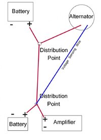
He states that there should be a distribution point where the alternator, battery, fuse block, and audio all get their power - and a voltage sensing wire at that point also. Now if we remember from the video, accessories should be powered by the alternator, not the battery (it is just there for support when the alt. can’t keep up). This way as soon as the amplifier needs power, the alternator can ramp up and give the extra needed voltage.

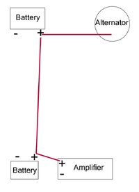
So, my wonderment is – if wired the conventional way (first drawing), with the main power wire going from the alternator to the battery – maybe to a second battery in the back, then to the amplifier – doesn’t the alternator recognize the need as quickly? And when it ramps up, wouldn’t it go right to the amplifier because the batteries are already full so the current should just go right past them – no?

I’m no good with drawings or sketches but I included two for the basic idea. I’m not sure if the guy in the article would be OK with the two distribution points or if it should be just one. Just thought that would save a lot of wire.
 

Attachments

  • Conventional.jpg
    Conventional.jpg
    36.7 KB · Views: 7
  • Distribution Points.jpg
    Distribution Points.jpg
    41.7 KB · Views: 9

The_Roadie

Lifetime VIP Donor
Member
Nov 19, 2011
9,957
Portland, OR
The two distribution point idea is fine. Fatter wires, or two in parallel going the same place, have similar benefit.

Think of wires as hoses carrying water. If you open a spray nozzle at the far end of a hose suddenly, the lack of pressure (voltage) takes a while to be seen back at the source at the house piping. In electrical terms, that happens at the speed of light, so the speed of electrical transmission isn't a problem. What *is* the problem is that the hose cause pressure drop along the way, depending on how narrow the hose is. What pressure the house (alternator) can put out gets partially lost through the hose. All the water (current) that goes in one end comes out the end, but the pressure (voltage) is lower, and the amount of useful energy in the nozzle spray (power delivered to the amplifier) is lower because of the wastage in the hose.

Alternators all have internal regulators nowadays, so the desired voltage will only appear at the alternator's output post, so the only improvement you can make is to install fatter wires.

In my day job, we design 1000 Amp power supplies that have to DELIVER an accurate voltage (typically within 5-10 millionths of a volt) to the destination, which may be 12 feet away. The only trick that works is remote feedback sensing (called Kelvin or Force/Sense connections). To deliver 20 Volts accurately, we often have to apply 30-35 Volts to the input wire (hose), which is sometimes as fat as the welding cables used for auto audio wiring.
 

Black LT

Original poster
Member
Dec 4, 2011
211
So, some variation of the second picture would allow current from the alternator to reach the amplifier better than the first picture?

To deliver 20 Volts accurately, we often have to apply 30-35 Volts to the input wire
That brings up another thing I wondered. If done like pic two and the alternator is having to put out 16 volts to maintain the 14.2 (whatever it's regulated at) to the amp, isn't everything else getting the 16 volts also?


EDIT - probably not - the alternator is probably making 16 volts internally to maintain the 14.2 at the post.
 

jimmyjam

Member
Nov 18, 2011
1,634
Black LT said:
So, some variation of the second picture would allow current from the alternator to reach the amplifier better than the first picture?


That brings up another thing I wondered. If done like pic two and the alternator is having to put out 16 volts to maintain the 14.2 (whatever it's regulated at) to the amp, isn't everything else getting the 16 volts also?


EDIT - probably not - the alternator is probably making 16 volts internally to maintain the 14.2 at the post.
:confused: huh? :crazy: i think you're overthinking....

all you need to concern yourself with is voltage drop between the alternator-battery-amp. get the biggest wire you can for your long run, copper not clad aluminum, high quality crimps on your connectors, clean mating surfaces
 

97blazer

Member
Nov 23, 2012
39
I agree with Roadie.

No sense wire in the first drawing but assuming it comes from the first bat then, for your use, the second drawing would be better. Although not by much. Do you have a single wire alt? IE no sense wire. then you're stuck unless you change back. No clue how well that would work.

To me the best setup is a volt meter AND and amp meter. An amp meter, properly wired, will always show if you're using alt current or bat current. Not necessary true with just a volt meter.
 

Black LT

Original poster
Member
Dec 4, 2011
211
I didn't put the sense wire in the first pic because I'm not sure exactly where the TrailBlazers get it from. But I do know our lights flicker and our audio is wired after the main battery.

I guess I should do like Jimmy said and just do what everybody else does - but that aint fixing anything!

huh? i think you're overthinking....
Yeah, I been told that before. Today (while I was working) I was thinking - How the hell did they ever think the world was flat? I know they weren't as advanced but everything in the sky that they saw was round - oh, but we're flat - wtf - did they think the squirrel fell off the universe when it went to the other side of the tree??? How was this uncomprehensable?


... and there was enough chat in this section! (audio stuff - not my bizarreness)
 

MAY03LT

Member
Nov 18, 2011
3,426
Delmarva
Black LT said:
I didn't put the sense wire in the first pic because I'm not sure exactly where the TrailBlazers get it from

The pcm monitors the ignition 1 circuit for system voltage.

Black LT said:
How the hell did they ever think the world was flat?

Because if someone were to walk to the edge they would fall off and die and it would hurt!
 

meerschm

Member
Aug 26, 2012
1,079
Thanks for the post.

led me take a walk through the service manual. seems the internal regulator in the generator provides a PWM signal that the PCM uses to goose up the engine speed when the generator needs it. it also can shut off ( or not turn on) the generator if the engine is under load and needs the horsepower, (like if you need to pass that truck or climb that big ass rock) or if it is still starting up, and not quite awake first thing on a cold morning.

the voltage monitor referenced by MAY03, i think, is used to set trouble codes if it is too low, or worse, too high, it is not used to control output of the generator.. control of the output is, as Roadie pointed out, internal to the generator.

will you only use your audio with the engine running? if not, you might consider an isolator. the isolator will keep the primary battery under the hood from running down from use of the one dedicated for your sound system. will allow the battery to charge up when you drive.

if you really want the lights to not dim, you could also put a relay in to completely sever the systems. so the lighting is smooth and solid when your sound is shaking the sidewalk.
 

The_Roadie

Lifetime VIP Donor
Member
Nov 19, 2011
9,957
Portland, OR
meerschm said:
led me take a walk through the service manual. seems the internal regulator in the generator provides a PWM signal that the PCM uses to goose up the engine speed when the generator needs it. it also can shut off ( or not turn on) the generator if the engine is under load and needs the horsepower, (like if you need to pass that truck or climb that big ass rock) or if it is still starting up, and not quite awake first thing on a cold morning.
Is that from the factory Helm manual? When I read that section of the theory of operation, I read that the output wire from the alternator to the PCM was just reporting the field signal, which would be PWM, but that the PCM only needs to know how hard the alternator was working. If the alternator was close to 100% duty cycle and putting out all it could, the PCM would be also monitoring the supply voltage and start going into its load-shedding routine. The load shedding routine is never mentioned in the Owner's Manual, but was a fascinating attempt to retain exterior lighting and engine operation in the face of a dying alternator and discharging battery. Never read that the PCM would increase engine RPM. That would be a bad thing to do while the vehicle was in gear.

The alternator suppression wire was mentioned for the cold weather start issue that almost everybody notices, and which was also not mentioned in the Owner's Manual. But I only read that the AC compressor would be dropped off-line for WOT passing situations. Yours says the alternator output will also be suppressed? Hmmmm, something new every day.

Just making sure you're also looking at a Helm manual. What year?
 

meerschm

Member
Aug 26, 2012
1,079
the roadie said:
Is that from the factory Helm manual? When I read that section of the theory of operation, I read that the output wire from the alternator to the PCM was just reporting the field signal, which would be PWM, but that the PCM only needs to know how hard the alternator was working. If the alternator was close to 100% duty cycle and putting out all it could, the PCM would be also monitoring the supply voltage and start going into its load-shedding routine. The load shedding routine is never mentioned in the Owner's Manual, but was a fascinating attempt to retain exterior lighting and engine operation in the face of a dying alternator and discharging battery. Never read that the PCM would increase engine RPM. That would be a bad thing to do while the vehicle was in gear.

The alternator suppression wire was mentioned for the cold weather start issue that almost everybody notices, and which was also not mentioned in the Owner's Manual. But I only read that the AC compressor would be dropped off-line for WOT passing situations. Yours says the alternator output will also be suppressed? Hmmmm, something new every day.

Just making sure you're also looking at a Helm manual. What year?

I was reading the factory three volume paper HELM manual for the 2003 TB. I was in the section on reported trouble codes associated with the generator. if I have time later, I could quote or provide the trouble codes involved.

my impression is that the "increase engine RPM" is my misstatement, more accurate probably is "adjust engine controls ( throttle position et al) to maintain RPM in the face of increased load. " I think simiar functions are included for AC loads at idle. (again a guess on my part, but it seems logical to use available state information ( A/C relay energized) when calculating input values for engine controls)


I was interested in my new understanding of what the signals to-from the generator were.

there are two signals from the generator. one input to turn it on, the other output (PWM) to indicate load ( field strength, I think)

conjecture on my part the design of logic to use the input, seems like WOT would be a good time to drop generator load, but this is only my guess.
 

The_Roadie

Lifetime VIP Donor
Member
Nov 19, 2011
9,957
Portland, OR
meerschm said:
my impression is that the "increase engine RPM" is my misstatement, more accurate probably is "adjust engine controls ( throttle position et al) to maintain RPM in the face of increased load. " I think simiar functions are included for AC loads at idle. (again a guess on my part, but it seems logical to use available state information ( A/C relay energized) when calculating input values for engine controls)
Understood. I have the 2004 Helm, and when I first bought the Roadiemobile I bought the Helm, and sat down for over a month and read it cover to cover in the evenings. The challenge of maintaining engine RPM when the AC compressor cycles on and off abruptly is exactly why a dirty/sticky throttle body causes so many issues after the PCM volatile memory is lost after a battery disconnection/discharge. The adaptive algorithms can deal with slow stickification as a TB ages, but don't seem to have enough adaptiveness (adjustment authority) to handle the sudden and unexpected deterioration in response with empty memory tables. The solutions don't converge to a properly damped response, so you end up with stalling and RPM overshoots around the 600 RPM setpoint. The sudden increase in load of an AC compressor might be 10-15 HP, which is why the PCM needs some advance warning of engagement, rather than just wait for the RPM to drop, then do something about it. A fully-loaded up alternator is only about 2 HP power draw, so the effect is a lot less, and I didn't see that detail discussed in the manual. I try to get into the minds of the designers and what motivates them when I speculate on WHY they made certain choices. But when I discuss feature details of how things operate, I try to keep guessing to a minimum. Just my style.
 

meerschm

Member
Aug 26, 2012
1,079
drifting off topic, but has anyone reverse engineered the software?

should be feasable, and with the tuners and colleciton of tools, it seems possible to actualy see what inputs and logic are applied to the engine controls.

the service manual is not specific. (language like ....is used by the PCM...)

just wondering out loud.
 

meerschm

Member
Aug 26, 2012
1,079
the roadie said:
Understood. I have the 2004 Helm, and when I first bought the Roadiemobile I bought the Helm, and sat down for over a month and read it cover to cover in the evenings. The challenge of maintaining engine RPM when the AC compressor cycles on and off abruptly is exactly why a dirty/sticky throttle body causes so many issues after the PCM volatile memory is lost after a battery disconnection/discharge. The adaptive algorithms can deal with slow stickification as a TB ages, but don't seem to have enough adaptiveness (adjustment authority) to handle the sudden and unexpected deterioration in response with empty memory tables. The solutions don't converge to a properly damped response, so you end up with stalling and RPM overshoots around the 600 RPM setpoint. The sudden increase in load of an AC compressor might be 10-15 HP, which is why the PCM needs some advance warning of engagement, rather than just wait for the RPM to drop, then do something about it. A fully-loaded up alternator is only about 2 HP power draw, so the effect is a lot less, and I didn't see that detail discussed in the manual. I try to get into the minds of the designers and what motivates them when I speculate on WHY they made certain choices. But when I discuss feature details of how things operate, I try to keep guessing to a minimum. Just my style.

description for DTC P1637 says in part," Under certain operating conditions the PCM can turn OFF the generator by turning off the 5 volt signal on the generator turn ON signal circuit"

since the Generator L terminal signal is represented on the PCM scan tool data list, Engine 2, it should be possible to determine when and if the PCM turns off the generator. I may give it a go and report back. will be a week or so before I take her out again

it looks like the signal can be set by the PCM, turning off the generator, or can be set by the generator internal regulator when a fault is detected, turning off the generator, and reporting an error, which sets the P1637.I suspect the PCM is smart enough to know if it commanded the generator disable not to set the trouble code.
 

Forum Statistics

Threads
23,669
Posts
641,796
Members
19,103
Latest member
tkvova

Members Online