- Dec 23, 2012
- 197
No the battery is a little over a year old. Xs power d3400. Maybe I should ground the amps to a different location?? I don't know. I'm out of ideas.
While we know the amperage capacity, I think the real figure is in terms of wattage. At first it would seem silly to rate alternators in terms of amps when you don't see powerplants bragging about being "20,000 A!," it's all about their KW/MW/GW rating. But since we're working in a known voltage here (rather than having loads applied at various voltages depending on the requirement), we could just figure that if the 150A rating is at 12V, the alternator puts out 1800 watts and that's why they give amp ratings. The duty cycle would affect overall wattage I would imagine (and therefore power input).BlazingTrails said:Here's what I don't understand about the system as a whole. Increasing the voltage reduces the amperage, so how does it save fuel to drop the voltage? It seems to me that it would just increase the amperage which would actually put more load on the alternator. Either way mine does the same thing. Also are you reading the "idiot" gauge on the dash for the voltage or are you monitoring the system with an external meter? Because if your using the cluster gauge, that would be a fatal flaw on your part. It could be that the stepper motor is wearing out.


I think it'd be simple, depending on how the duty cycle is commanded higher. If it's a PWM signal or something, I'm sure a dupe signal could be rigged up with a little know-how.BlazingTrails said:I'm going to start working on bypassing this system. I'm sure it can be done, I'm going to do some testing and let you guys know what I come up with.
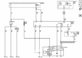
it communicates via class II serial data.IllogicTC said:I think it'd be simple, depending on how the duty cycle is commanded higher. If it's a PWM signal or something, I'm sure a dupe signal could be rigged up with a little know-how.
What kind of audio you running?shepherd92683 said:No I haven't ran with it unplugged. The best solution I have so far since it's summer is having the air on. It seems when that system runs I stay over 14. Even when I turn it off it stays that high. I need to tinker more with the wiring of the rear battery and go from there. More copper lugs need to be ordered and soldered first then testing will take place. I really would've rather ran an extra 14v alternator/system for the stereo but that is a whole other expense far out of the budget.
The wire running TO the alternator is not a part of the serial bus. This would be the wire to intercept to take deliberate control.coolasice said:it communicates via class II serial data.
2 AQ HDC3 18's, AQ 2200, Boston 4100, 2 sets of Boston Pro 60SE...06TrailblazerLSS said:What kind of audio you running?
Do you know what decibels youre hitting? Probably sounds great huh?shepherd92683 said:2 AQ HDC3 18's, AQ 2200, Boston 4100, 2 sets of Boston Pro 60SE...
http://www.motor.com/article.asp?article_ID=1606%C2 for some discussionBlazingTrails said:Here's what I don't understand about the system as a whole. Increasing the voltage reduces the amperage, so how does it save fuel to drop the voltage? It seems to me that it would just increase the amperage which would actually put more load on the alternator. Either way mine does the same thing. Also are you reading the "idiot" gauge on the dash for the voltage or are you monitoring the system with an external meter? Because if your using the cluster gauge, that would be a fatal flaw on your part. It could be that the stepper motor is wearing out.
Yes!!! It makes no sense!!!bobdec said:coolasice, Been paying a lot of attention to my voltage as a result of this thread. Other day after 30 mins of H'way driving voltage was at 13 volts and we hit stop go traffic in Atlanta. Sitting there stopped w/headlights (DLR's), brake lights, radio, AC front and rear blowers going the darn PCM kept the voltage at 13 no matter what the engine RPM. I then turned on rear defogger and put front blower up all the way to load the system up fully, and it still stayed at 13. Traffic cleared we started moving again and the voltage stayed that way for 10 mins till we go home. I shut it down a restarted and the voltage went to 14.5 for a bit and settled at about 14. Bottom line I'm totally confused on how the PCM makes he duty cycle decision. According to books the headlights and rear defroster should have upped the voltage, but that did not happen.. There is more to this picture than we are seeing..
There is a 1/0 run from the front battery to the rear battery. There is also a 1/0 run to the alt post. There is a run to a distribution block on the rear to allow for 2 1/0 runs, one to each amp. The Boston amp takes 2 4ga inputs so I have reducers to make that work.bobdec said:Another tidbit to store away, DLR' are not considered headlights, probably because running, dash and tails are not on w/them
As far as the OP's problem, trying to remember DC power theory is hurting my head. I we have a dual parallel battery setup. Batteries are not the same size and capacity. The battery negative sides are tied together at the engine block albeit via different gauge wires from the batteries. There is a GBCM current monitor that monitors negative side current between front battery #1 and the block feeding the PCM. After reading this thread and the link thread I was not able to see how the two battery positive sides are linked together. No mention of a battery isolator, if there is none, then the audio will draw current from both batteries almost equally except for wiring gauge and resistance in the positive and negative connections. Question to sheperd.. how is the amp positive wired up to the stock positive system, is it a heavy gauge wire under the hood to the #1 battery. rember as the #2 battery starts drawing down the audio will be pulling current from the amp to #1 positive terminal. That wiring is an unknown to us..


Yes I do like it but would like more power. Never had it on a term lab but to guess I'd say mid to upper 40's.06TrailblazerLSS said:Do you know what decibels youre hitting? Probably sounds great huh?
My truck, as with yours, hits great when voltage is up- and mediocre when not.
BlazingTrails said:Here's what I don't understand about the system as a whole. Increasing the voltage reduces the amperage, so how does it save fuel to drop the voltage? It seems to me that it would just increase the amperage which would actually put more load on the alternator. Either way mine does the same thing. Also are you reading the "idiot" gauge on the dash for the voltage or are you monitoring the system with an external meter? Because if your using the cluster gauge, that would be a fatal flaw on your part. It could be that the stepper motor is wearing out.
meerschm said:for some discussion
increasing voltage does not reduce amperage.
higher voltage from the alternator will push current into the battery, causing chemical changes, and charging the battery. past a certain point, will cause trouble. the battery chemestry depends on temperature, (higher voltage required to charge at lower temps)
higher voltage also increases current for most loads. (headlights, seat heaters, defrosters...) this is for the most part waste heat, which does take energy from what you put in the tank.
regulated power supplies will take more current as source voltage is reduced, but there are plenty of resistive loads on the system, and these are the primary loads.
I started a new thread to follow up.BlazingTrails said:I respectfully disagree with everything you just said.
This is true for POWER transmission applications. the power company uses a very high voltage to pass a lower amperage so that the size of the wire can be smaller which costs less. But for DC theory where the resistance is constant (seat heaters, lights, rear defroster) the amperage will increase as voltage increases.BlazingTrails said:Here's what I don't understand about the system as a whole. Increasing the voltage reduces the amperage, so how does it save fuel to drop the voltage? It seems to me that it would just increase the amperage which would actually put more load on the alternator. Either way mine does the same thing. Also are you reading the "idiot" gauge on the dash for the voltage or are you monitoring the system with an external meter? Because if your using the cluster gauge, that would be a fatal flaw on your part. It could be that the stepper motor is wearing out.
Yes, but the current is supplied by the alternator, if the engine is running, the battery is just behaving as a big capacitor in the circuit, I don't see how a second battery adds any value. I guess it could be benificial at idle, but I thought a modern RVC alternator would ramp up the idle speed or dump other loads to strive to keep the battery at a high state of charge.Mounce said:Stereo systems that are designed for high performance require large amplifiers which draw large currents. The second battery is for the stereo (maybe I should call it radio?). The need for the second battery is for extra amperage/power to the amplifiers so that they can run at their max potential and in turn, put out better power to drive the speakers. Some people also add more alternators to produce the power and/or keep the extra battery(s) at full charge or to recharge them in a more timely manor.