SOLVED! Loss of Communication when trying to read DTC's

kmpcc05

Original poster
Member
Aug 23, 2020
13
wilmington, nc
The Tech 2 just flashes "loss of communication" and beeps repeatedly when I try to get it to read codes.

Also, it will request info from the ECU for the SPS just fine but after I load the updates from the PC and hook it up to the obd port, it cycles through everything and then says failure. It seems like it sort of communicates, for instance one of the updates was to calibrate the fog lights.. it switched the lights on at one point and I could hear other clicks and noises from under the hood but ultimately, it fails.

I tried to do a crank relearn and it let me get all the way to the final step before it started the flashing beeps of failure. Sometimes it will say I may have entered the wrong vehicle after failing to do something but I know for sure the info is correct.
 

mrrsm

Lifetime VIP Donor
Supporting Donor
Member
Oct 22, 2015
8,202
Tampa Bay Area
Welcome to GMT Nation...

Some suggestions:

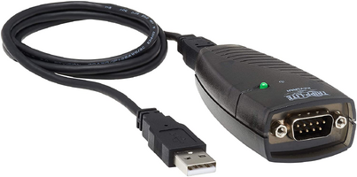
Replace whatever you are using right now as a Serial Communications Port on your Laptop Computer with THIS particular USB to Serial Port Adapter:


1598190408879.png

(1) Remove and Re-Install the PCMCIA Card from the Front to the BACK Slot AFTER spraying a small amount of CRC Electronic Solvent Spray into BOTH Slots. DON'T OVER DO IT... SPRAY IN JUST ENOUGH TO WET DOWN THE TINY CONNECTIONS... and then RETURN The Card back into the Front Slot again after blowing out the unit with Canned Air. Avoid getting the Solvent on the LCD Screen from the INSIDE, as the Blue Screen Coating may be affected.

(2) Remove the VCI Module Slide Lock Unit and use some "Canned Air" to blow out BOTH sides of the Pin Interface. Spray it around with the CRC Solvent. When DRY ... Re-Install the VCI Module and CAREFULLY Slide Lock it back in place.

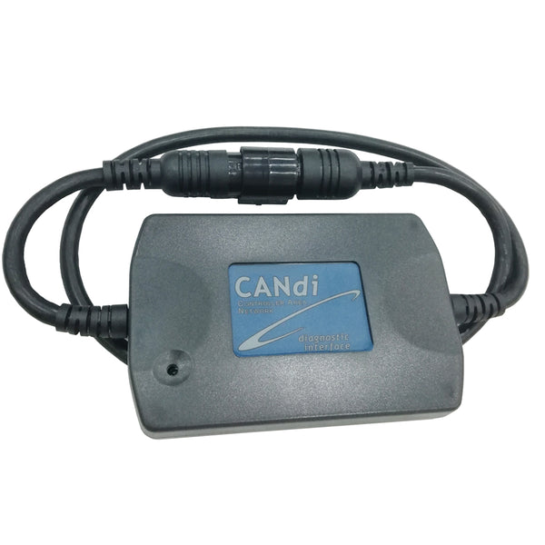
(3) Remove the CANDi Module and Spray the inner Push Pin Slots with the CRC Solvent.

(4) Use the CRC Spray on BOTH ends of the Data Link Connector Cable and Blow them out Dry with the Canned Air..

(5) Install the Loop Back Connector Test Module into the RS-232 Port on the TECH 2 then Power Up the Unit and run a few Loop Back Tests to see if anything shows up.

(6) Remove the PCM Cable Connectors and Spray out BOTH sides with the CRC Solvent, and once they are Dry..,Reinstall them on the PCM, being careful to properly align the Weather-Pack Seals.

(7) Run a COMPLETE Bubble Skin Keyboard check on EVERY SINGLE BUTTON....Watch for their responses VERY Closely on Screen.

(8) Test your Battery Voltage and Do NOT attempt any Reads-Writes if the Battery is less than 12.5 Volts and in Good Shape. Clean and Re-Install your Battery Cables prior to attempting ANY Key/ON Testing.

NOTE:

AVOID PLUGGING IN THE 110 AC TO 12 Volts DC 1 Amp Power Adapter into the TECH 2 while connected to the DLC inside of the Vehicle, as the Alternating Current Noise can interfere with Successful Calibration Reads & Writes to and from the PCM. Use the Cigar Lighter Power Outlet and Plug that Power Source into the 3.5mm Connector on the DLC Cable itself ...NOT into the TECH 2 Power Port on the Unit.

(9) When EVERY Module and Cable Interface is Bone Dry... Re-Assemble them all and install the Unit in the Vehicle DLC and attempt to read DTCs. DO NOT HAVE ANY ACCESSORIES OR HEADLIGHTS TURNED ON PRIOR TO STARTING ANY TESTING.

(10) Avoid trying to use SPS on your present PCM until you have attempted Steps 1-9 as it may already be 'scrabnoid' from prior unsuccessful Calibration Reads-Writes.

If you need to replace any of the Tech 2 Components or Hardware-Cables... Visit this Vetronix Site as they are probably State Side and may be selling OEM Replacement Components ...including PCMCIA Pre-Formatted and Pre-Loaded Linear Ram Cards for fairly reasonable prices. Just check out "The Crawler" at the bottom of this page:


Last edited:

TJBaker57

Lifetime VIP Donor
Member
Aug 16, 2015
3,199
Colorado
The Tech 2 just flashes "loss of communication" and beeps repeatedly when I try to get it to read codes.

Also, it will request info from the ECU for the SPS just fine but after I load the updates from the PC and hook it up to the obd port, it cycles through everything and then says failure. It seems like it sort of communicates, for instance one of the updates was to calibrate the fog lights.. it switched the lights on at one point and I could hear other clicks and noises from under the hood but ultimately, it fails.

I tried to do a crank relearn and it let me get all the way to the final step before it started the flashing beeps of failure. Sometimes it will say I may have entered the wrong vehicle after failing to do something but I know for sure the info is correct.

Someone with more Tech 2 experience can jump in here,,, but from what I have read there can be NO aftermarket electronics (like radios, etc) 'alive' when doing any programming.

Tried reading codes from some other module just to see if it's the module you are trying to read or the Tech 2 system?

The Tech 2 reads codes differently than most obd scanners. The generic scanner likely isn't requesting some of what the Tech 2 requests and thus would not trigger the error.

What results do you get with the Tech 2 when checking the class 2 data, like pinging each module, etc? For example my VTD module, node address 0x30, has never been seen by me on the network and the Tech 2 reports no communication with that module when tested. I don't even know if I have such a module! Whether or not it would cause trouble if I ever try to reprogram a module I don't know.
 

mrrsm

Lifetime VIP Donor
Supporting Donor
Member
Oct 22, 2015
8,202
Tampa Bay Area
This may sound 'MORE than a LITTLE Unorthodox...' And I would ONLY try this as a Last Resort... But Back in the Day when Delphi was still Stateside and they were Building their PCMs HERE... Before they were allowed to FLASH the EEPROMs in all those Units, they would First have to subject them all to a Four Hour COLD FREEZE Cycle... then if they passed their Diagnostics Tests...they would subject them to a Four Hour Baking Cycle. Again... those that PASSED Both Thermal Extremes Tests were allowed to be Programmed with Virgin Calibrations for their New Vehicle Installations.

So If NONE of the collective suggestions work to remedy this problem, try removing the PCM from the Vehicle and after placing it into a Tightly Closed Pair of Zip-LoK Baggies (along with a few Silica Gel Moisture Absorbency Packettes) ... Stick it right into the Freezer for around 4 Hours or so... and then right after setting up ALL of your Tech 2 Gear well in advance... Remove the PCM from the Freezer...install it in the Truck and run through your Diagnostics and DTC Reads to see if all goes well and the Class 2 Communications return. If they fade over time as the PCM thermally normalizes to ambient temperature... it may indicate a problem with the PCM.
 
Last edited:

kmpcc05

Original poster
Member
Aug 23, 2020
13
wilmington, nc
Well, I guess it isn't the Tech 2 since I was able to read and add module updates to my 98 s10. I'm leaning towards a bad ECM at this point. I didn't think so at first bc I have no engine issues but it could be a fried wire somewhere that won't allow communication.
 

Mooseman

Moderator
Dec 4, 2011
26,026
Ottawa, ON
I'd pull the xomb out of the main splice pack and connect only the OBD port and the PCM. If still no comms, check the wiring and then the PCM.
 
  • Like
Reactions: mrrsm and TJBaker57

kmpcc05

Original poster
Member
Aug 23, 2020
13
wilmington, nc
Well I tried an ecm I bought online and it failed at programming just like mine. I also couldn't read the dtc's when it was hooked up.

I have a remote starter but I disconnected the power to it and still got loss of communication.
 

Mooseman

Moderator
Dec 4, 2011
26,026
Ottawa, ON
I'd pull the comb out of the main splice pack and connect only the OBD port and the PCM. If still no comms, check the wiring and then the PCM.

Did you try the above?
 

kmpcc05

Original poster
Member
Aug 23, 2020
13
wilmington, nc
Did you try the above?
I'll try that this evening since it's my night off but another thing I noticed is that I can read ABS codes and some of the data stuff. Also, I can test the door locks and interior lights, etc but it still beeps and flashes slowly... I have to repeatedly press the on or off button to test the doors or the lights.

It's such an odd thing and I can't find anyone on the internet with a similar problem. All of them have other issues related to the ecm but my truck runs perfectly fine. My only issues are I don't have door chimes, my gauges don't turn on automatically, and I can't fully communicate thru the tech 2.
 

mrrsm

Lifetime VIP Donor
Supporting Donor
Member
Oct 22, 2015
8,202
Tampa Bay Area
Agree with @Mooseman about Yanking the Front AND the Rear Splice Packs and watching the linked Video showing how Will Robinson performs BOTH tasks on a Trailblazer with the 4.2L Engine using a "Scope on a Rope" Lighted Probe to test Powers & Grounds under Load and uses his Tech 2 in tandem with his PICO Oscilloscope in order to examine the performance of EVERY Module via the Tech 2 to *Ping* integrity of the Class 2 Network Wiring:


Here is another Tech using a "Pocket Sized" Oscilloscope using essentially the same Technique but making it easier with a fancy "DLC Breakout Wiring Harness":


Both Techniques using Oscilloscopes allow for examining "Voltage Over Time" segments and visualize the Class 2 0-7 Volts DC "ON & OFF" Square Wave Behavior.

IT IS VERY IMPORTANT TO REMEMBER THAT ANY MODULE ON THE GM CLASS 2 NETWORK THAT SHORTS TO GROUND (LOW) OR TO 12 VOLTS DC (HIGH) CAN BRING ON UNUSUAL BEHAVIOR IN OTHER MODULES SINCE THEY ALL RESIDE ON THE SINGLE NETWORK COMMUNICATIONS WIRE WHERE THEY CONVERGE AT THE TWO SPLICE PACKS.

The Hantek Model 1008c version is available on Amazon (The Prices Have DROPPED substantially! and is MUCH CHEAPER than the PICO Scope and will be just as functional. There are TONS of Hantek Videos on Youtube to check out how these Devices work:

Everything You'll need for a Working Oscilloscope...

(1) The Basic Hantek Model # 1008C Kit
(2) A Mini Amp Clamp
(3) A 20:1 Signal Attenuator

...are all listed at this Link:

 
Last edited:
  • Like
Reactions: Mooseman

kmpcc05

Original poster
Member
Aug 23, 2020
13
wilmington, nc
Agree with @Mooseman about Yanking the Front AND the Rear Splice Packs and watching the linked Video showing how Will Robinson performs BOTH tasks on a Trailblazer with the 4.2L Engine using a "Scope on a Rope" Lighted Probe to test Powers & Grounds under Load and uses his Tech 2 in tandem with his PICO Oscilloscope in order to examine the performance of EVERY Module via the Tech 2 to *Ping* integrity of the Class 2 Network Wiring:


Here is another Tech using a "Pocket Sized" Oscilloscope using essentially the same Technique but making it easier with a fancy "DLC Breakout Wiring Harness":


Both Techniques using Oscilloscopes allow for examining "Voltage Over Time" segments and visualize the Class 2 0-7 Volts DC "ON & OFF" Square Wave Behavior.

IT IS VERY IMPORTANT TO REMEMBER THAT ANY MODULE ON THE GM CLASS 2 NETWORK THAT SHORTS TO GROUND (LOW) OR TO 12 VOLTS DC (HIGH) CAN BRING ON UNUSUAL BEHAVIOR IN OTHER MODULES SINCE THEY ALL RESIDE ON THE SINGLE NETWORK COMMUNICATIONS WIRE WHERE THEY CONVERGE AT THE TWO SPLICE PACKS.

The Hantek Model 1008c version is available on Amazon (The Prices Have DROPPED substantially! and is MUCH CHEAPER than the PICO Scope and will be just as functional. There are TONS of Hantek Videos on Youtube to check out how these Devices work:

Everything You'll need for a Working Oscilloscope...

(1) The Basic Hantek Model # 1008C Kit
(2) A Mini Amp Clamp
(3) A 20:1 Signal Attenuator

...are all listed at this Link:

Those videos were very helpful. I've been trying to find something like that for days.. guess I should've searched for Trailblazer instead of Colorado.

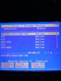
I haven't started testing yet but I uploaded a screenshot of my class 2 data. Only 6 show up and they're all Active. Does that seem right for an 05 Colorado? Seems like there should be more.
 

Attachments

  • IMG_20200831_185640422.jpg
    IMG_20200831_185640422.jpg
    339.1 KB · Views: 9
  • Like
Reactions: mrrsm

Mooseman

Moderator
Dec 4, 2011
26,026
Ottawa, ON
There should be more, like HVAC, radio, PDM, DDM. Seems like all the convenience stuff is not there.
 

kmpcc05

Original poster
Member
Aug 23, 2020
13
wilmington, nc
There should be more, like HVAC, radio, PDM, DDM. Seems like all the convenience stuff is not there.
So since in the first video, he had no communication and I have limited comms.. does that narrow down where I should start testing or should I just start under the steering wheel and go from there?
 

Mooseman

Moderator
Dec 4, 2011
26,026
Ottawa, ON
Check the wiring diagrams. Could be a secondary splice pack that has lost comms.
 

mrrsm

Lifetime VIP Donor
Supporting Donor
Member
Oct 22, 2015
8,202
Tampa Bay Area
The issue is that ANY GM-GMC Vehicle using the Class 2, Single Wire Dual Splice Pack arrangement can suffer from symptoms that will have UNIVERSAL Solutions...even with variations on the Type and Number of Modules that should all *Ping* Up and be ready to rock. But what is good here is that you recognize now that you'll have to 'widen your gaze' when looking for ALL of the possible Class 2 Network Problem Areas.

And THAT Idea takes us over to the "GROUNDS". Have look at this Video and see if THIS Guy has a way of pin-pointing the problems that may center around Cleaning Up the Ground Contacts where the OTHER side of the Class 2 Black Wire Grounding Splice Packs meet up to establish... "Common Ground".

There MAY be some variation for your particular Colorado where these Splice Pack Grounds are situated elsewhere in the vehicle. Right now...You are functioning "Out side of the Box' and here at GMTN... Sometimes THAT is the Best Place to BE. :>)


SP-105 located on the driver's side near the battery
SP-106: located on the Passenger side behind the engine Air-Box

SP 105 Grounds ALL of THESE:

Electronic Brake Control Module (EBCM)
Headlamp Beam-Select Relay (relay #47) and headlamps
Fuel pump and fuel-level sender
Fuel Pump (relay #51)
Run/Crank (relay #61)
Brake Reservoir level switch (sensor)
Wiper relay 1 (relay #57)
Wiper relay 2 (relay #63)
Windshield motor
Windshield washer pump motor
Electric door locks – driver's
Outside electric mirrors
Inside mirror (courtesy lamps on the mirror)
Tail lamps (all... t-s, brake-lamps, back-up lamps, 3rd brake lamps) Front turn-signal and marker lamps
Fog-lamp relay
Fog-lamps
Cargo lamp
Horn


SP 106 Grounds ALL of THESE:

Electronic Brake Control Module (EBCM)
Automatic transmission shift-lock control solenoid
HVAC control module
HVAC evaporator temperature sensor
Data Link Connector
Transfer-case control module (4WD only)
Transfer-case control switch (4WD only)
Window switch, right rear (crew cab only)
Door lock and window switch – front passenger
Heated seats option
Headlamp dimmer switch
Turn-signal/multi-function switch
Accessory switch (not sure what this is)
Hazard Lamp switch
Auxiliary power outlets (two)

Later on ...Check out THIS 12 Volt DC set up for any issues:


PDC (Power Distribution Center & Fuse Block)

 
Last edited:

kmpcc05

Original poster
Member
Aug 23, 2020
13
wilmington, nc
The issue is that ANY GM-GMC Vehicle using the Class 2, Single Wire Dual Splice Pack arrangement can suffer from symptoms that will have UNIVERSAL Solutions...even with variations on the Type and Number of Modules that should all *Ping* Up and be ready to rock. But what is good here is that you recognize now that you'll have to 'widen your gaze' when looking for ALL of the possible Class 2 Network Problem Areas.

And THAT Idea takes us over to the "GROUNDS". Have look at this Video and see if THIS Guy has a way of pin-pointing the problems that may center around Cleaning Up the Ground Contacts where the OTHER side of the Class 2 Black Wire Grounding Splice Packs meet up to establish... "Common Ground".

There MAY be some variation for your particular Colorado where these Splice Pack Grounds are situated elsewhere in the vehicle. Right now...You are functioning "Out side of the Box' and here at GMTN... Sometimes THAT is the Best Place to BE. :>)


SP-105 located on the driver's side near the battery
SP-106: located on the Passenger side behind the engine airbox

SP 105 Grounds ALL of THESE:

Electronic Brake Control Module (EBCM)
Headlamp Beam-Select Relay (relay #47) and headlamps
Fuel pump and fuel-level sender Fuel Pump (relay #51)
Run/Crank (relay #61)
Brake Reservoir level switch (sensor)
Wiper relay 1 ( relay #57)
Wiper relay 2 (relay #63)
Windshield motor
Windshield washer pump motor
Electric door locks – driver's
Outside electric mirrors
Inside mirror (courtesy lamps on the mirror)
Tail lamps (all... t-s, brake-lamps, back-up lamps, 3rd brake lamps) Front turn-signal and marker lamps
Fog-lamp relay
Fog-lamps Cargo lamp Horn


SP 106 Grounds ALL of THESE:

Electronic Brake Control Module (EBCM)
Automatic transmission shift-lock control solenoid
HVAC control module
HVAC evaporator temperature sensor
Data Link Connector
Transfer-case control module (4WD only)
Transfer-case control switch (4WD only)
Window switch, right rear (crew cab only)
Door lock and window switch – front passenger
Heated seats option
Headlamp dimmer switch
Turn-signal/multi-function switch
Accessory switch (not sure what this is)
Hazard Lamp switch
Auxiliary power outlets (two)

Later on ...Check out THIS 12 Volt DC set up for any issues:


PDC (Power Distribution Center & Fuse Block)

I'm definitely not saying grounds couldn't be a factor but I did sand down around the bolts for those packs in the past to get a stronger connection.

I guess the fact that my issue was so spontaneous that it seems like wear and tear would be less likely. I tried to crank the truck a couple times with a battery that I assume had a dead cell. I did a reset by connecting the pos and neg cables and it fired up. From that point on even after replacing the battery it still had no chimes/radio and the gauges often don't come on w/o assistance (pressing trip button.. using blinker). In fact when I am in the class 2 of the tech2, IPC doesn't show up at all in the list until I press the trip button and then it shows up as Active. And everything else functions fine on the truck.

I've started jumping the wires but nothing beyond the first 6 modules is waking up so far...
 

mrrsm

Lifetime VIP Donor
Supporting Donor
Member
Oct 22, 2015
8,202
Tampa Bay Area

kmpcc05

Original poster
Member
Aug 23, 2020
13
wilmington, nc
So I was unplugging harnesses under the hood to see if a bad sensor might be causing the communication issue.. that didn't help but at one point it caused the "service 4wd" to come up on the dash and I couldn't engage 4wd. Even after plugging everything back in, it still wouldn't work.

At that point just to see what would happen, I hooked up the tech 2 and cleared the atc codes, which fixed it. So even though I can't read codes, apparently I can clear them.
 

TJBaker57

Lifetime VIP Donor
Member
Aug 16, 2015
3,199
Colorado
So even though I can't read codes, apparently I can clear them.

This is particularly curious as the command to clear codes has the prerequisite of reading the codes first!


Edit: just thought that through a bit and remembered that the Tech 2 requests codes with a status byte of 08, a manufacturers status, as part of the initialization process. The user doesn't see or know this and the codes retrieved are not displayed but perhaps this alone allows the clearing of codes eithout the user first electing to read them.
 
Last edited:

kmpcc05

Original poster
Member
Aug 23, 2020
13
wilmington, nc
This is particularly curious as the command to clear codes has the prerequisite of reading the codes first!


Edit: just thought that through a bit and remembered that the Tech 2 requests codes with a status byte of 08, a manufacturers status, as part of the initialization process. The user doesn't see or know this and the codes retrieved are not displayed but perhaps this alone allows the clearing of codes eithout the user first electing to read them.
I just think the car gods hate me but that's probably the logical reason for it..
I can't remember if I mentioned it on this particular thread or not but a couple times I was able to read the dtc code by repeatedly turning the key from off to on. It still has a slow beep and flickering screen. Not that it matters tho since the code is a crank relearn and I'm never able to complete that before the loss of communication occurs.
 

mrrsm

Lifetime VIP Donor
Supporting Donor
Member
Oct 22, 2015
8,202
Tampa Bay Area
It is very important for you to Run Diagnostics with a DVOM on the DLC Port of your Vehicle. This Instructional Video should help with these procedures:


Also... Here is more Information regarding Module Communications Diagnostics:


...and understanding How the CAN System Operates...and How It Fails might also be involved:


More DLC and CAN Bus Diagnostic Videos are available ...HERE:

 
Last edited:

TJBaker57

Lifetime VIP Donor
Member
Aug 16, 2015
3,199
Colorado
Something worthy of mention, as far as I know there is no CAN system in use on a 2005 Colorado. They run the same as our pre-2008 trucks which is SAE J1850 VPW. Still good to have some knowledge of CAN bus (ISO 15765-4)
 
  • Like
Reactions: mrrsm

kmpcc05

Original poster
Member
Aug 23, 2020
13
wilmington, nc
I tested the dlc and I have the correct readings on 16, 4, and 5 but I looked up how much voltage pin 2 should have and for my year it apparently should be 1.5 to 7 volts but I only get half a volt.

Also now the port isn't powering up the tech 2 but if I plug the barrel end of the cigarette adapter in, the little indicator lights up red even before I've plugged it into the aux port. When I do plug it in, I then can power on the tech 2 like normal.

This happened after I tried the unplug harnesses and sensors experiment. Not sure if that caused an issue with the tech 2's power supply or if I did something that affected the port. Ftr, a regular scanner will still power on thru the dlc and read codes.

Does the low voltage on pin 2 narrow my issue down a little or am I still just down the rabbit hole?
 

TJBaker57

Lifetime VIP Donor
Member
Aug 16, 2015
3,199
Colorado
how much voltage pin 2 should have and for my year it apparently should be 1.5 to 7 volts but I only get half a volt.

A multimeter cannot accurately read the rapidly fluctuating pulses of pin 2. It goes from 0 to 7 maybe hundreds of times a second. Voltmeters cannot read that. The most I have seen is maybe 3 volts but I only saw that by making a video of the meter display and it also has to have active traffic on the bus to get any kind of reading.

This short video might indicate the kind of pulsing seen on the data lines. My signal tracer reacts to the pulsing.....

 
  • Like
Reactions: mrrsm

TJBaker57

Lifetime VIP Donor
Member
Aug 16, 2015
3,199
Colorado
Also now the port isn't powering up the tech 2 but if I plug the barrel end of the cigarette adapter in, the little indicator lights up red even before I've plugged it into the aux port. When I do plug it in, I then can power on the tech 2 like normal.

This happened after I tried the unplug harnesses and sensors experiment. Not sure if that caused an issue with the tech 2's power supply or if I did something that affected the port. Ftr, a regular scanner will still power on thru the dlc and read codes.


If the Tech 2 will not power on through the DLC but another scanner will that suggests to me your Tech 2 cable may be the problem. After using my tech 2 extensively for 8 or 9 months I had an issue with the cable. They do not tolerate twisting much I discovered and my cable shorted out and became a twisted mass of melted wires.
 

mrrsm

Lifetime VIP Donor
Supporting Donor
Member
Oct 22, 2015
8,202
Tampa Bay Area
Ordinarily, the Tech 2 is the last item that should get turned on or off after the Power circuit has been established. However, in your present situation, the internal Mornsun DC-to-DC Power Converter may be having issues as a result of accidentally getting rapidly being switched on and off because of a sketchy Power and Ground. If that item is in question, Dr. Shock has this excellent R&R Video of How To Repair the Tech2 as follows:

Mornsun Part #s VRB1205LD-15W or VRB1205LD-15WR2


kmpcc05

Original poster
Member
Aug 23, 2020
13
wilmington, nc
Well, I've come to the end of this weeks long journey with a solution. It turns out it was the first thing I tried.. the adapter that retains the chimes.

I originally replaced it with a used one I bought online but I guess that one was bad too. I didn't have a tech 2 at the time and by the time I did, I'd already moved on to suspecting the bcm, pcm, etc.

Today I completely removed the radio harness and the tech 2 worked seamlessly with the truck's computers. Oh well. Live and learn.
 

Forum Statistics

Threads
23,681
Posts
641,969
Members
19,138
Latest member
wentzben

Members Online