I'm traveling from White Sands Missile Range, NM to Ft. Jackson SC. About 50 miles ago I got the REP light for the APPs. I pulled over and cleared it with torque. It came on again so I'm at a hotel in Mississippi. Last time I got the code I checked all the reference voltage and got 5 volts at the pedal, fan and TB. Replacing the pedal seemed to fix it for a little while because I have driven about 1500 miles since I replaced it. This is the third one! Oreilly is closed until 0730 tomorrow, so I'm staying here tonight and will go there in the morning. It's 25 miles away, so I hope it makes it. On a good not I have gotten about 21 mpg average since leaving NM.
You are using an out of date browser. It may not display this or other websites correctly.
You should upgrade or use an alternative browser.
You should upgrade or use an alternative browser.
Kinda stranded
- Thread starter pennywise
- Start date
I know you checked the 5V ref... But I don't know if you did it the way this bulletin says...
The following diagnosis might be helpful if the vehicle exhibits the symptom described in the PI.
Condition/Concern:
Reduced power light on and DTC P1680 P1221 and/or P1271 stored in the PCM
Recommendation/Instructions:
Monitor the 5V reference to the Accelerator Pedal Position ( APP ) sensor, circuit 1274, using Peak Min/Max on a Fluke 87. Refer to Si document 1454678 for the 5V reference schematics. Command the fan clutch control "on" with the Tech 2 at 50%. If when commanding the fan clutch on, the 5V reverence spikes to battery voltage, the concern is the 5V reference shorted to battery voltage intermittently inside cooling fan clutch. Replace the fan clutch to repair this concern.
.
Please follow this diagnosis process thoroughly and complete each step. If the condition exhibited is resolved without completing every step, the remaining steps do not need to be performed. If these steps do not resolve the condition, please contact GM TAC for further diagnostic assistance.
Models:
(02 - 05 Chevrolet Trailblazer and Trailblazer EXT) and (02 - 05 GMC Envoy, Envoy XL and Envoy XUV ) and (02 - 05 Buick Rainier) and (02 - 04 Oldsmobile Bravada)
Note the underlined sentence... Without a tech2 this is going to be pretty tricky and plus your on the road so well, thats gonna be hard. But this may be the underlying issue and not the pedal assem.
the roadie said:If you're not in slow traffic you can unplug the fan clutch to see if the flakiness goes away.
Ah, I see what is happening now.. I think... All the reference leads from certain assemblies head to the PCM (Or BCM whichever) from multiple sources with different "channels" or "PID's" over a single wire that comes from a block that all the ref wires go to. So when the clutch is flaking out and hitting the ref lead with 12V it is temporarily taking out the signals from whatever other assemblies are on that branch. Unhooking the fan clutch takes that out of the equation to let the rest communicate freely without the "noise".
Which is why the engineers ran all the leads to a common block instead of daisy chain so that if one assembly was to completely lose com. you weren't disabling an entire group of systems because one system or even one wire at that went down.
Right ?
pennywise said:Thanks for the replies. I will unplug it tomorrow when I head back out.
If you do that and do happen to get into traffic shut it down if your going to sit more than a minute. Might help keep you from heating up. But remember that when you do shut down the engine is going to actually get hotter for a bit after its shut down so I wouldnt do an off on off on a bunch over a few minutes or it will go the opposite way.
I replaced the fan clutch not too long ago, so it should be under waranty. The only thing I need to try to figure out is how to change it, if that is the problem, when I am at school. I don't remember what brand it was but I bought it at either autozone or oreillys. I have the receipt somewhere in the truck.
pennywise said:I replaced the fan clutch not too long ago, so it should be under waranty. The only thing I need to try to figure out is how to change it, if that is the problem, when I am at school. I don't remember what brand it was but I bought it at either autozone or oreillys. I have the receipt somewhere in the truck.
Did you replace it before or after you started having this problem?
pennywise said:It was replaced after replacing the first APPs and before the second one.
hmmm, I was hoping it was replaced before the pedal and everything that happened. It is completely possible that the fan is the cause but I dunno, in that case it is starting to sound like a wiring issue. But eh I am leaning strongly toward the clutch still being the problem.
Either way... Good luck tomorrow...
The OBDII data bus is the one critical wire that goes to all modules. The PCM has a bunch of different and separated 5V reference (reference in this case just meaning electrically clean, accurate, and not messed with too much by other circuits). If the designers weren't limited by the number of pins available in the connectors, the "best" way (not the cheapest) would be to have one reference voltage for any sensor that needs one. Since they were constrained, they often grouped things together and used a shared reference voltage. This allows for unwanted interaction between circuits, though. The interaction means that multiple sensors can interact with each other and make each other look bad.McGMT said:Ah, I see what is happening now.. I think... All the reference leads from certain assemblies head to the PCM (Or BCM whichever) from multiple sources with different "channels" or "PID's" over a single wire that comes from a block that all the ref wires go to.
That's right, but the only sensors sharing this specific 5V reference are two on the accel pedal, two on the throttle body, and one on the fan clutch. The redundancy on the accel pedal and throttle body are to make sure that a single sensor or wiring fault won't cause a WOT behavior and the vehicle would runaway like a Toyota. That's why faults on this specific reference circuit give you a REP light and only a "limp home or to the side of the road" behavior. Yes, to put the fan clutch on the same circuit as the accel pedal and throttle body was a very poor design decision.So when the clutch is flaking out and hitting the ref lead with 12V it is temporarily taking out the signals from whatever other assemblies are on that branch.
Pretty much, but the noise is really not a data communication message packet fault, but a true analog crosstalk or spike on the sensor reference. The sensors on the accel pedal and throttle body are basically potentiometers.Unhooking the fan clutch takes that out of the equation to let the rest communicate freely without the "noise".
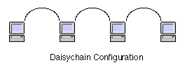
This is the slight misconception you have, and it isn't bad. The "blocks" you're thinking of are the "Splice Packs", two locations where the data communication wires all come together to a shorting plug. The messages are never really run as a daisy chain where each module has to retransmit the signal to the next one in the chain,Which is why the engineers ran all the leads to a common block instead of daisy chain so that if one assembly was to completely lose com. you weren't disabling an entire group of systems because one system or even one wire at that went down.
Right ?
View attachment 22717
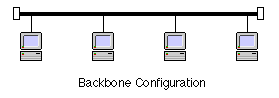
and it isn't wired as a common long wire (backbone) where each module touches the data comm wire but it's basically all of them always tied together.
View attachment 22718
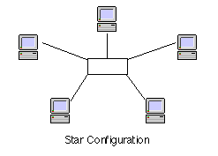
They come together in the Splice Packs in case one module starts putting jibberish on the line and garbling comm on the wire for all modules, like one guy heckling a speech and then you can't hear the main speaker. This is called a star configuration:
View attachment 22719
You can pull the wire from one module at a time out of the Splice Pack at the center of the star and see if the gibberish disappears and the remaining modules can communicate properly. They actually did this SOLELY to make it possible to troubleshoot down the line, because it's a total PIA to get to each of the modules and just disconnect their data comm line to see who's talking when they shouldn't be.
Attachments
2x1968muscle
Member
- Dec 4, 2011
- 17
I see this thread is a few days old now, but something to throw in the mix is the Accelerator Pedal Sensor that you keep exchanging.
There are known issues with certain brands of aftermarket pedal assemblies. I changed my pedal sensor to get rid of a "clunk" sound and went through 2 replacement pedals in short order (same error code P1271) until I took the advice found on this forum and put in a GM part. The problem went away immediately.
Nothing worse than a quiet "bong" sound and then a christmas tree of CEL and REP lights illuminated on the dash.
Hopefully you got your issue resolved...

I still have the aftermarket one in it. I have had to replace it again since the last time I was able to log onto the forum. It went out twice on the way back from school. I've made it home but I'm so tired of dealing with it. I am goin to check the circuit one more time, but I'm pretty sure it's the aftermarket part causing the problem. I'm moving in a month to the new duty station where I'm told I will have no time off at all for the next two years, so I want to get it fixed beforehand. I have checked both reference wires at the pedal, fan and throttle body. I also disconnected the fan for a short distance the first time it stopped working correctly. I don't understand how everyone I've put in has stopped worknig correctly. Are they all made that cheaply?
(
I am also in the service. Army stationed in Fort Irwin. I bought a trailblazer as soon as I landed in LA. My pedal position sensor went out so I replaced it with an aftermarket (Dorman) and it went out in a couple weeks. I looked on forums and found out they were junk so bought an OEM and have been good for at least two months.We don't make much money, but invest in an OEM replacement. You can find it on eBay for $110. You won't regret it
pennywise said:I still have the aftermarket one in it. I have had to replace it again since the last time I was able to log onto the forum. It went out twice on the way back from school. I've made it home but I'm so tired of dealing with it. I am goin to check the circuit one more time, but I'm pretty sure it's the aftermarket part causing the problem. I'm moving in a month to the new duty station where I'm told I will have no time off at all for the next two years, so I want to get it fixed beforehand. I have checked both reference wires at the pedal, fan and throttle body. I also disconnected the fan for a short distance the first time it stopped working correctly. I don't understand how everyone I've put in has stopped worknig correctly. Are they all made that cheaply?
I am also in the service. Army stationed in Fort Irwin. I bought a trailblazer as soon as I landed in LA. My pedal position sensor went out so I replaced it with an aftermarket (Dorman) and it went out in a couple weeks. I looked on forums and found out they were junk so bought an OEM and have been good for at least two months.We don't make much money, but invest in an OEM replacement. You can find it on eBay for $110. You won't regret it
I have had the GM part on the truck for about a month now and it seems to have worked. I drove from White Sands, New Mexico to Fort Hood, Texas with no problems. Then I towed my wifes HHR to Fort Leonard Wood, Missouri. So I'm sure it's fixed. I'm also surprised at how well this vehicle does towing that much weight that far.
Eric04
Member
C-ya
Member
- Aug 24, 2012
- 1,098
Same question I had, but then I thought like someone who may be experiencing the issue: research. How is the OEM assembly holding up? Did the problem come back for the same reason?The_Roadie said:Why?