Hard to Remove Front Disconnect Assembly, 2005 Envoy

tfoley95

Member
Dec 14, 2018
1
Wisconsin
This thread saved my ass this weekend! The housing cracked off at the oil pan just like others have done. I don't have much to add that others haven't covered. I mostly wanted to say thank you for everyone that's posted in here. The only advise I can give is be very careful with how far you drill into the old bearing. In fact, I marked my bit with tape to be sure. I broke 3 drill bits during this project. Take your time, be patient and you'll eventually get it.

Also, if you are replacing the actuator as well, test it first. Plug it in and leave it dangle. Turn the key to run (no need to start it) and flip it to 4 wheel drive. The plunger on the actuator should poke out about 1 1/8 inches. Flip the 4 wheel drive off and then check it again. It will only be out about 1/2 inch. The actuator I received with the housing is bad, and it cost me about an hour because those little 8mm bolts that hold the actuator to the housing are a pain in the ass to remove without taking the housing off the truck.

Again, thanks everyone for posting, and my wife thanks you too because it saved us at least $500 in the checkbook!
 
  • Like
Reactions: Camdo and Mooseman

Tantara

Member
Feb 3, 2019
1
Minnesota
I just want to say thanks this thread was extremely helpful to me. I did however not have room for my drill. Instead I used a tungsten carbide burr in a dremel tool to weaken the housing wall. This included generous amounts of WD 40 to cool the tool and wash away chips. I finished the job with a hammer and chisel. Thanks for the help.
 

Aec678

Member
Nov 7, 2019
23
Pennsylvania
Hard to Remove Front Disconnect Assembly, 2005 Envoy, Part 1

This is the story of how I fixed my 4WD. I have included mistakes, durations, true costs and suggest improved procedures for future jobs. We learn from everything, and I hope you may gain from my mistakes.

My 2005 GMC Envoy SLT, 4.2L inline 6 cyl. (10 years old at the time of this writing) had dysfunctional 4 wheel drive. I purchased the car in this condition, and so did not know all the history. There were no symptoms such as grinding, whirring, chatter etc, other than it did not work. All lights were normal on the dash, no service lights.

I jumped to the conclusion that the transfer case was bad. I impulsively purchased online the factory transmission repair manual and contemplated rebuilding the transfer case. I later discovered that I could buy a used transfer case for less than the manual, so I bought that too. I then read the vehicle repair manual to see how the transfer case is removed when I discovered there is a thing called the "intermediate shaft disconnect assembly". A eureka moment.

I jacked the right front wheel and engaged the 4WD. It was obvious that the right axle was not connecting to the differential side as it should when in 4WD. I removed the electric actuator of the disconnect assembly and actioned it in my hand with a Tech2. Its plunger worked okay. I placed a drift in the actuator hole to mimic the electric actuator and rotated the right tire. The axle would not engage no matter how hard I pressed on the drift. I could feel the sliding fork move smoothly within, everything felt okay, the grease looked clean, no metal shards could be seen. It was a mystery why the disconnect assembly was not working, but removing it was the next thing to do.

The Intermediate Shaft Disconnect Assembly is also called: Front Disconnect Assembly , Splined Disconnect, Intermediate Shaft Bearing Assembly, and Clutch Fork Housing Assembly to name a few. I will here after call it "assy", short for assembly and not for the PITA it was to remove.

I had the official GM service manual for this vehicle, so I thought the job would go smoothly. I would follow the procedure to the letter.

I purchased a new assy from USPowerTrain.com for $213 S&H included. I saw it on eBay, but purchased it directly from them on the telephone, as the return policy is more favorable when buying direct. I wanted to return the unit in case it was not needed. They claim their unit is engineered better than OEM. I got it in 4 days and was completely satisfied.
http://rover.ebay.com/rover/1/711-5...0001&campid=5338077216&icep_item=161509948512
Tel: 888-759-0814 ask for online sales. Tell them you saw it on eBay for $213.

I made two attempts to remove the old assy. On the first. I could not remove the right CV axle assembly without separating the lower ball joint from the steering knuckle. Although the manual says this is not necessary, In my case, it was. I did not have the proper tools to do this, and the car is my one and only daily driver. I reassembled the car. 9 hours work, but next time would be a snap to get back where I left off.

I purchased online two tools called out in the manual, which I now consider a must for this job.
1. J43631 Lower ball Joint Separator. used $128 on eBay.
2. J24319-B Puller. Substituted OTC 7503 Outer Tie Rod Remover. ToolSource.com new $55 plus $10 S&H.
http://www.toolsource.com/outer-tire-remover-p-62094.html
pic 12
View attachment 68670


I would caution against buying China imports, as these are high stress tools. I looked at a look alike HFT puller and saw the jaws were thin, not aligned, could not tell if forged or cast, and the screw threads were not smooth. OTC7503 can be anyone's part number. Be wary buying online. You want to see the "OTC an SPX Brand" logo. Ottawa Tool Company is the best.

Now for my second attempt:

  1. Loosen wheel hub axle bolt, wheel lugs, jack car, remove tire.
  2. Disconnect speed sensor wire at the plug on the chassis back to the steering knuckle. To disconnect the electric plug: first pull it straight perpendicular from the chassis frame, then remove the grey safety lock by depressing the middle barb with a small screw driver while pulling, then disconnect the plug by squeezing the locking tab on the neck while pulling apart the plug assy. Disconnect the speed sensor cable clamps with a small screw driver prying up in the hood pocket.
  3. Disconnect the brake line clamp on the back side of the steering knuckle.
  4. Disconnect brake line mounting block on frame.
  5. Separate outer tie rod from steering arm.
  6. Separate stabilizer link from lower control arm. You will need a 7mm Allen wrench.
  7. Separate strut yoke from lower control arm.
  8. Unbolt 2 upper strut bolts from chassis mount. Remove strut from car.
  9. Separate upper ball joint from upper control arm.
  10. Separate lower ball joint from lower control arm.
  11. Pull wheel hub steering knuckle assembly from front axle. Set aside on blocks under wheel well with brake line still attached.
  12. Remove right front CV axle using a brass drift and 2 lb mason hammer against tripot housing.
  13. Now you have clear access to the front axle disconnect.
pic 11
View attachment 68669

  1. Disconnect the electric plug from the disconnect assy. Remove the actuator.
  2. Remove 4 bolts holding assy to oil pan.
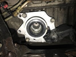
  3. Pry assy from oil pan. This may take some effort, and may be impossible to do so. It should pop off. If the assy doesn't budge, you have a corroded fused assy. If so, some serious press action is required, and the assy casting is probably going to be damaged in the removal process. Assess your options at this point.
a. Remove the outer case half of the assy and take a look at what is wrong with it. You may be able to repair the unit without removing it from the oil pan. In my case I could see the shifting fork was severely worn, and I could have replaced just that part. But all that worn aluminum was in the grease and there are many small needle bearings in the assy. Will you have peace of mind.
b. Continue to remove the assy and possibly crack the oil pan or damage the bore. Leading to a huge repair project.


I chose to replace the assy despite the risks.

To remove the stuck assy from the oil pan:
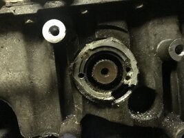
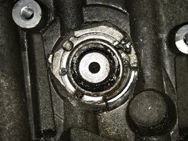
Use 3 jack screws, 3/8-18 x 2.5 full thread, with square nuts on the backside of the assy. Distribute the point load of the jack screws on the oil pan with thick metal backer pads. Jack screws are the socket head cap screws in pic 8 . Square nuts are not as likely to spin without a wrench. The steel pads are about 2 x 2 x .25, 2 x 3 x .38, and .75 x 2.5 x .50 and small filler block .50 x 1 x .31 Just scraps I had lying around.
pic 8

View attachment 68667
pic 9
View attachment 68668


I applied quite a bit of torque to the jack screws until the assy popped. The oil pan is remarkably strong. What popped was the casting of the assy. This was a nerve racking operation, but I would do it again. The oil pan is strong. The force required to break the casting is substantial and highlights how fused together these parts were.
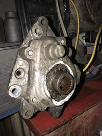
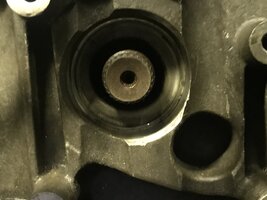
Here is the assy. You can see where the casting broke.
pic 2

View attachment 68666

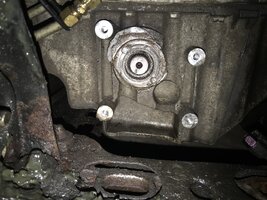
and the oil pan with the broken piece stuck in the oil pan. The assy oil seal prevents removal of the intermediate shaft.
pic 1

View attachment 68665


Continued in Part 2
http://gmtnation.com/forums/topic/13749-hard-to-remove-front-disconnect-assembly-2005-envoy-part-2/
The second part link leads to nothing 😟 it says it can’t be found....is there a way to get to part 2?
 

TJBaker57

Lifetime VIP Donor
Member
Aug 16, 2015
3,192
Colorado
The second part link leads to nothing 😟 it says it can’t be found....is there a way to get to part 2?
Go back to the beginning of this thread. Part 2 is the second post!

 
  • Like
Reactions: Aec678

Forum Statistics

Threads
23,680
Posts
641,940
Members
19,134
Latest member
jakeinbacon

Members Online