Electronics question for any of you engineers out there...

Envoy10

Original poster
Member
Dec 4, 2011
86
Ok I'll try to explain this the best I can as Im still learning electronics.

Im looking to power a 12V-0.12A fan AND a stepper motor driver at 12V-1.2A(Pololu - A4988 Stepper Motor Driver Carrier)

My existing setup consists of a 36V-8.8A power supply wired in parallel to three stepper motor drivers. This is for my existing 3axis CNC router setup.
Im looking to add this 4th pololu driver(link above) to retro-fit a 3d printer extruder for 3d printing.

Im trying to figure out how I would supply power for both of these components. I was thinking of buying a 12V wall adapter and either connecting it to my surge protector OR wire the wall adapter to my existing 36V power supply. (to save a plug opening on my surge protector) First Q, would wiring the adapter to the 36V power source rather than the surge protector(110V) affect the rated output?

2nd Q, after I cut the end of the adapter and separate the + and - wire, how would I wire the rest? Both the fan and driver will be receiving their required 12 volts, Im just unsure about how to wire it up so the fan receives its 0.12A and the driver its 1.2A. Would I have to split two + and two - wires from the end of the wall adapter(parallel) and just add the two different required resistors needed for both components? Or am I totally off? Any help would be much appreciated.

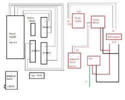
Hope I explained it well enough without any visuals but if it makes it easier I can sketch up a quick diagram of my setup.

NOTE: the motor this pololu driver will be driving is rated at 6.5V-1.2A(http://store.qu-bd.com/product.php?id_product=14)
 

RZAwora

Member
Apr 15, 2012
196
Envoy10 said:
Ok I'll try to explain this the best I can as Im still learning electronics.

Im looking to power a 12V-0.12A fan AND a stepper motor driver at 12V-1.2A(Pololu - A4988 Stepper Motor Driver Carrier)

My existing setup consists of a 36V-8.8A power supply wired in parallel to three stepper motor drivers. This is for my existing 3axis CNC router setup.
Im looking to add this 4th pololu driver(link above) to retro-fit a 3d printer extruder for 3d printing.

Im trying to figure out how I would supply power for both of these components. I was thinking of buying a 12V wall adapter and either connecting it to my surge protector OR wire the wall adapter to my existing 36V power supply. (to save a plug opening on my surge protector) First Q, would wiring the adapter to the 36V power source rather than the surge protector(110V) affect the rated output?

2nd Q, after I cut the end of the adapter and separate the + and - wire, how would I wire the rest? Both the fan and driver will be receiving their required 12 volts, Im just unsure about how to wire it up so the fan receives its 0.12A and the driver its 1.2A. Would I have to split two + and two - wires from the end of the wall adapter(parallel) and just add the two different required resistors needed for both components? Or am I totally off? Any help would be much appreciated.

Hope I explained it well enough without any visuals but if it makes it easier I can sketch up a quick diagram of my setup.

NOTE: the motor this pololu driver will be driving is rated at 6.5V-1.2A(NEMA 17 Stepper Motor 3kg/cm - QU-BD 3D Printer CNC Mill Store)

First off, I will say I'm not an electrician or electronics engineer. I do, however, have experience with low voltage electronics. I would definitely check out any info I give you with someone more knowledgeable. Anyway, for what it's worth...

1) The 12v Wall Adapter will have an "input voltage" rating. This rating is typically "AC100-240v" thus it must be supplied with between 100v and 240v. If your talking about wiring it to the "Output" of your 36v power supply, that won't work. The 12v Wall Adapter won't give you any power at all. If you are talking about wiring the 12v Wall Adapter to the "Input" side of the 36v power supply, that would be fine, assuming the "input" to the 36v PS is 110v. This would be a simple parallel wiring to the input leads of the 36v power supply.

2) For your second question(s)... you don't need to regulate how they get their power. In other words, you wire them parallel to the "output" side of the 12v power adapter, and they will pull the amperage they need, in your case the fan will pull the .12A and the stepper motor driver will pull the 1.2A. You must make sure the 12v adapter you are using is rated to power both. I will note that the stepper driver motor specs say it can draw up to 4A so you'll need a 12v adapter rated for >5A since you don't typically want to use more than 80% of the PS rated output. Now, the wiring would be parallel, with the correct capacitors the driver carrier calls for. I didn't see anything calling for a resistor. Also, the driver carrier calls for a "logic power supply" of 3-5.5v, where is this coming from?
 

The_Roadie

Lifetime VIP Donor
Member
Nov 19, 2011
9,957
Portland, OR
rzawora said:
... I would definitely check out any info I give you with someone...
You got it just perfectly, while I was doing errands. (I'm a EE with a 39 year career in semiconductor test system design and support, so I've seen or used most everything short of gigawatt lasers. :wink:)

The logic power supply is not the only thing missing. The stepper motor driver needs a drive control logic signal from a microcontroller somewhere. I assume Envoy10 has this somewhere? This would indeed be easier to visualize if there was a block diagram available of the overall layout.
 

Envoy10

Original poster
Member
Dec 4, 2011
86
rzawora said:
Now, the wiring would be parallel, with the correct capacitors the driver carrier calls for. I didn't see anything calling for a resistor. Also, the driver carrier calls for a "logic power supply" of 3-5.5v, where is this coming from?

The logic power supply will be coming from the breakout board I forgot to mention in my initial post. It's powered 5V via USB to my computer.
I drew this up on Paint to show my existing setup and on the right in red how I should add these two things if Im understanding everything right. Is this correct? I did see this on the driver webpage that I dont understand :These supplies should have appropriate decoupling capacitors close to the board, and they should be capable of delivering the expected currents (peaks up to 4 A for the motor supply). I know capacitors hold voltage but thats about the extent of my knowledge about them.

There's a 3rd wire for this old computer fan Im using, it doesnt need to be connected to anything, does it? Just heatshrink the end? Also, the motor supply voltage for the Pololu board can be anywhere from 8V-35V, I chose 12V because of their availability and so I didnt need to drop the voltage for the fan if wired in parallel. Is using 12V for this application ok or should I look for a higher voltage? Thanks for the help rzawora and roadie
 

Attachments

  • CNC electronics setup.jpg
    CNC electronics setup.jpg
    68.9 KB · Views: 10

RZAwora

Member
Apr 15, 2012
196
Sorry Envoy10 because this is where I got lost at...you'll have to wait for Roadie or someone else to give you most of the answers you're looking for. I can tell you though, that if you hook up the wires to the fan and it's working, then no, you don't need anything hooked up to the 3rd wire. A fan is a simple positive-red/negative-black hook up, the 3rd wire is probably yellow or white and is a speed sensor that would normally go to the motherboard/case-display/etc. I got lost and confused because the sentence you pointed out; both supplies should have decoupling capacitors, but then it also says the driver carrier should have a large (> 50 µF) electrolytic capacitor across motor power (VMOT) and ground somewhere close to the board. I do understand, and can explain that the decoupling capacitors are there to "take away" any "electrical noise" so they're getting clean power and also helps the voltage regulator maintain correct voltage when there is quick changes in power demand. An electrolytic capacitor is the type that stores up energy and release it on demand...this is the type of capacitor some people use on car audio systems. When the energy isn't peak it recharges itself for the next demand moment...prob milliseconds in this size to recharge. Anyway, what I'm at a loss on is how to install these, and I don't have the knowledge to read that nifty little diagram at the bottom of their page to tell you where they go...for those reasons you'll have to wait for Roadie or someone else more knowledgeable. Good luck...what is a 3d printer anyway?
 

Envoy10

Original poster
Member
Dec 4, 2011
86
Ok thanks for the explanations. I'll wait to see if Roadie or someone else can fill in the blanks.

A 3d printer is just that, device that prints 3d objects in the form of layers with ABS or PLA plastic filament.
This may explain it better: [video=youtube;yEiZYfpa75Q]http://www.youtube.com/watch?v=yEiZYfpa75Q&feature=fvwrel[/video]
 

RZAwora

Member
Apr 15, 2012
196
That thing is badass!!! Cool. I want one. Lol. Don't know what I'd do with it, but I want one. One day. Anyway, yeah Roadie or someone should be able to finalize you schematics. Sorry I can't help any further...it's now out of my comfort zone. Besides that thing looks expensive and I don't want to be the one causing it to fry. Lol. Good luck.
 

Envoy10

Original poster
Member
Dec 4, 2011
86
You can make almost anything you can think of and draw up on a CAD - within size. Im still waiting for parts in the mail but I cant wait to try this thing out.
 

The_Roadie

Lifetime VIP Donor
Member
Nov 19, 2011
9,957
Portland, OR
1) I agree the third wire on the fan is a speed sensor. You can safely cap it off.

2) I need a link to the details of the breakout box, unless it's the thing otherwise you linked to they call a carrier. Who sold the thing that plugs into the USB port?

3) Where is the software coming from that runs this system?

4) The breakout document links to the Allegro data sheet and says it's important to understand those concepts. (I went to school near one of their plants - used to be called Sprague Electric). Have you delved into that spec sheet much to understand how the current limit works? It's important.

5) In general, electricity has a set of pretty good analogies to water. Pressure = voltage. Flow = current. Thin hoses are like thin wires - undesirable due to resistance, which slows down flow and steals pressure.

A capacitor is a storage element that gets charged up by current, like a water tank being filled slowly with water, and then can be dumped if needed to do things, like flushing a toilet. That's how you can do things like move a motor that might need an instantaneous current flow of 4 Amps, even though your power supply can only deliver 1 A continuously.

You store up energy in the capacitor, and then deliver it in a short burst. In this case, a 1 Amp power supply can deliver a 4A surge for let's say 0.1 second, but it has to take at least 0.4 seconds to recharge. A stepper motor might need the surge for only 0.005 seconds (5 milliseconds or thousandths of a second), and then it has to recharge for 0.020 seconds (20 milliseconds).

The "Farad" is the unit of capacitance that relates to the amount of energy being stored (usually real world capacitors are rated in milliFarads), and the capacitor can be chosen only after you know the current it has to deliver, the voltage, and the time it's going to be called on to deliver (smooth out) the energy. Energy in this case is analogous to how many gallons of water are in the toilet flush tank.

Anybody whose eyes haven't glazed over is invited to continue. :wink:
 

RZAwora

Member
Apr 15, 2012
196
Roadie great analogies. You must be a master at what you do. If I ever delve into something electronic you'll be my go to guy... Luckily for both of us, I have a slight understanding, but no interests in doing things this complicated. That's why people like you get paid the big bucks. Haha. It's very nice of you to help him figure this out. I envy your vast amounts of knowledge and commitments.
 

Envoy10

Original poster
Member
Dec 4, 2011
86
the roadie said:
1) I agree the third wire on the fan is a speed sensor. You can safely cap it off.

2) I need a link to the details of the breakout box, unless it's the thing otherwise you linked to they call a carrier. Who sold the thing that plugs into the USB port?

3) Where is the software coming from that runs this system?

4) The breakout document links to the Allegro data sheet and says it's important to understand those concepts. (I went to school near one of their plants - used to be called Sprague Electric). Have you delved into that spec sheet much to understand how the current limit works? It's important.

5) In general, electricity has a set of pretty good analogies to water. Pressure = voltage. Flow = current. Thin hoses are like thin wires - undesirable due to resistance, which slows down flow and steals pressure.

A capacitor is a storage element that gets charged up by current, like a water tank being filled slowly with water, and then can be dumped if needed to do things, like flushing a toilet. That's how you can do things like move a motor that might need an instantaneous current flow of 4 Amps, even though your power supply can only deliver 1 A continuously.

You store up energy in the capacitor, and then deliver it in a short burst. In this case, a 1 Amp power supply can deliver a 4A surge for let's say 0.1 second, but it has to take at least 0.4 seconds to recharge. A stepper motor might need the surge for only 0.005 seconds (5 milliseconds or thousandths of a second), and then it has to recharge for 0.020 seconds (20 milliseconds).

The "Farad" is the unit of capacitance that relates to the amount of energy being stored (usually real world capacitors are rated in milliFarads), and the capacitor can be chosen only after you know the current it has to deliver, the voltage, and the time it's going to be called on to deliver (smooth out) the energy. Energy in this case is analogous to how many gallons of water are in the toilet flush tank.

Anybody whose eyes haven't glazed over is invited to continue. :wink:

Yeah that was put well, easy to retain. Sometimes my head starts spinning trying to learn some of this stuff.

The breakout board and my existing setup is part of an electronics package I bought for a 3axis CNC router. (buildyourcnc.com)
I dont have any type of data sheet about the breakout board other than a suggested wiring diagram.(input pins for switches, e-stop, probes, etc and output pins for the motors) The breakout board is powered by my computer via USB(5V) and it hooks up through the old 25pin parallel port.

Right now the two main programs I'll be using are Mach 3 and LinuxCNC for my controller software. I've read the section on current limiting and I think I have it down. Though Im not sure what the last sentence means: Please note that the current limit is dependent on the Vdd voltage. VDD=5V in this case and I should . The Nema 17 motor(link above) is rated at 1.2A per phase. 2 phases, my current limit should be 2.4A and 70% of that is 1.68A. Which is what I should read on the motor using the given directions under 'full step mode'
 

The_Roadie

Lifetime VIP Donor
Member
Nov 19, 2011
9,957
Portland, OR
All that means is that the current limit can vary a bit from nominal depending on what the VDD level is. Not a totally critical part of the design. The 4988 has a built-in limit of 2A it looks like anyway.

The 12V power supply will need an electrolytic cap to smooth out the current pulses. Do you have any just lying around, or do you need to buy everything you use?

What sort of cap does the 36 V supply have?
 

Envoy10

Original poster
Member
Dec 4, 2011
86
the roadie said:
All that means is that the current limit can vary a bit from nominal depending on what the VDD level is. Not a totally critical part of the design. The 4988 has a built-in limit of 2A it looks like anyway.

The 12V power supply will need an electrolytic cap to smooth out the current pulses. Do you have any just lying around, or do you need to buy everything you use?

What sort of cap does the 36 V supply have?

I still haven't bought the driver or the power supply yet. Only the extruder/motor assembly. Thought I'd wait til I figure everything out or found one laying around unused but I have nothing.

I dont have any specs for the 36V PS, though I see them in there through the vents. Is there a way to know if a 12V power supply has an electrolytic cap before buying?
 

The_Roadie

Lifetime VIP Donor
Member
Nov 19, 2011
9,957
Portland, OR
A typical small wall-plug sort of 12V switching supply will not have any useful size capacitors inside. A cheap open-frame linear supply will certainly have one, since it has to smooth out lower frequency variations. Whatever you buy will require some easy math to choose the right cap.

I have a box full of old junk that may have something. PM me your contact details. :cool:
 

Forum Statistics

Threads
23,570
Posts
640,695
Members
18,880
Latest member
pjames

Members Online