- Dec 4, 2011
- 568
My conversion was performed with 18,000mcd white LED's. Because these are way too bright for nighttime use, I used a larger-than-normal resistor to bring the brightness down to match the intensity of the original bulbs. Your resistor value will vary depending on the particular LED and color that you use. I suggest using one of the various online resistor calculators to choose your starting resistor, then go to larger values of resistance to make your LED dimmer.
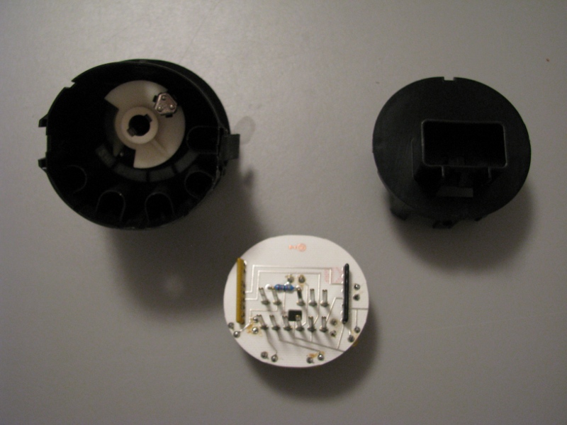
The switch disassembled. There are two tabs, one on either side of the case, that need to be pushed in and towards the back of the switch in order to pop the case apart. To reassemble, just snap the pieces back together.
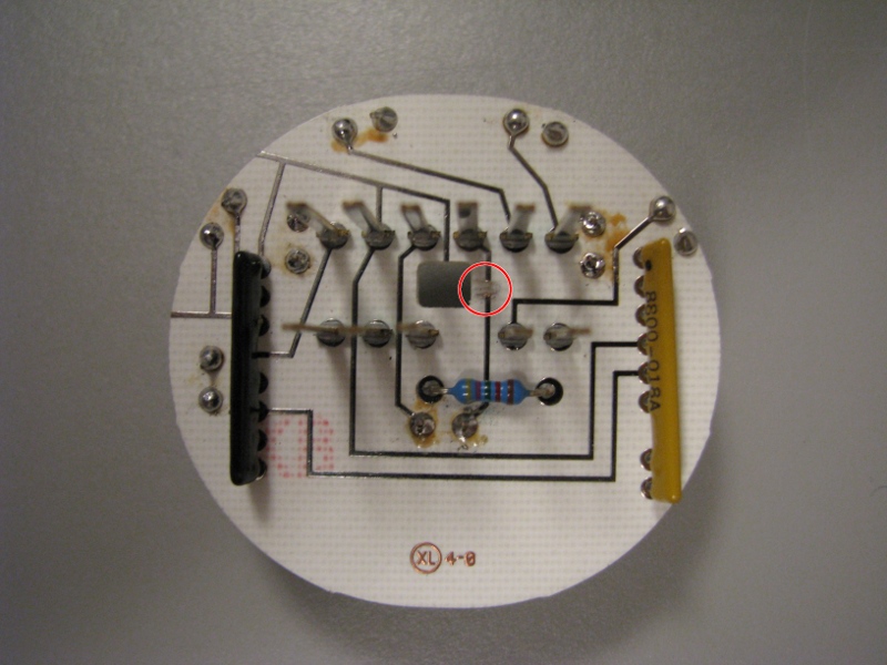
The back side of the circuit board needs one trace cut. Since the LEDs cannot take the full 12V power, we will be soldering resistors onto the circuit board to drop the voltage down near 2.6V.
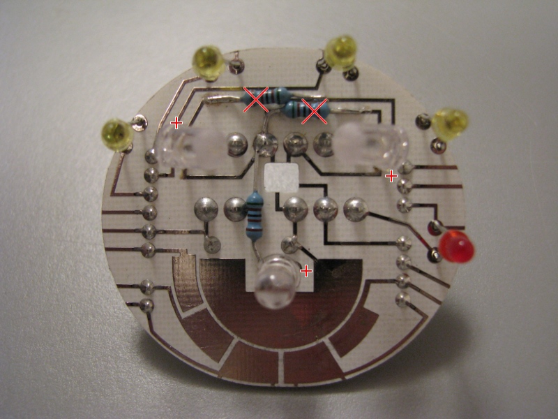
The red X's show the location where I used a dremmel to cut the circuit traces directly underneath each resistor. The resistors are then soldered to the circuit traces to bridge the gap and reduce the voltage to each LED. The lower resistor bridges the cut circuit from the back side, but there was more room to work with by putting the resistor on the front of the board. The lower leg of this resistor is connected to the negative lead of the LED. Take note of the '+' marks indicating the positive (longer) lead of each LED.
Before soldering each LED to the board, sand the lens with some 200-400 grit sandpaper to give them a frosted look. This will help spread out the light more evenly behind the switch. Measure the height of each light bulb before you remove them from the board. The LED's should be soldered on at approximately the same height.
Use a soldering iron with a narrow tip. Too much heat can damage the circuit board. Liquid solder flux can help greatly in getting a good connection between the resistor legs and the circuit board traces. Once you have finished soldering, you can (carefully!) plug the bare board into the wiring harness in your vehicle, making certain you have it turned the right direction. Failure to get this right can cause permanent damage to your 4x4 selector switch.
Watch the LED's closely as you turn the key to ignition. If you see an LED flash brightly then go out, it got too much voltage. Verify that you cut the proper circuit board traces, and measure your resistor values. If you put a voltmeter across the legs of the now-dead LED, you should only see about 2.6 volts.
If an LED does not light up, but did not flash when it first got power, you may have soldered it in with the wrong polarity. Remove the LED and solder it in the right direction. Also confirm that the resistors are soldered to the right locations.
Once you have all three LEDs lit up, place the front of the switch over the top of the circuit board and observe how they look. If you have noticeable bright spots, try bending the top two LEDs over slightly so they are not aimed directly at your switch face. With a little work, you can get the LED's to provide a uniform glow to all of the indicators on the switch face.
Once you are satisfied, you need to clean the solder flux off the circuit board. Wash the whole board under water and use an old toothbrush to lightly scrub the areas you soldered. If the water does not remove the flux, use alcohol to remove the rest, then wash in water again. Dry the board completely before reassembling the switch.
The switch disassembled. There are two tabs, one on either side of the case, that need to be pushed in and towards the back of the switch in order to pop the case apart. To reassemble, just snap the pieces back together.
The back side of the circuit board needs one trace cut. Since the LEDs cannot take the full 12V power, we will be soldering resistors onto the circuit board to drop the voltage down near 2.6V.
The red X's show the location where I used a dremmel to cut the circuit traces directly underneath each resistor. The resistors are then soldered to the circuit traces to bridge the gap and reduce the voltage to each LED. The lower resistor bridges the cut circuit from the back side, but there was more room to work with by putting the resistor on the front of the board. The lower leg of this resistor is connected to the negative lead of the LED. Take note of the '+' marks indicating the positive (longer) lead of each LED.
Before soldering each LED to the board, sand the lens with some 200-400 grit sandpaper to give them a frosted look. This will help spread out the light more evenly behind the switch. Measure the height of each light bulb before you remove them from the board. The LED's should be soldered on at approximately the same height.
Use a soldering iron with a narrow tip. Too much heat can damage the circuit board. Liquid solder flux can help greatly in getting a good connection between the resistor legs and the circuit board traces. Once you have finished soldering, you can (carefully!) plug the bare board into the wiring harness in your vehicle, making certain you have it turned the right direction. Failure to get this right can cause permanent damage to your 4x4 selector switch.
Watch the LED's closely as you turn the key to ignition. If you see an LED flash brightly then go out, it got too much voltage. Verify that you cut the proper circuit board traces, and measure your resistor values. If you put a voltmeter across the legs of the now-dead LED, you should only see about 2.6 volts.
If an LED does not light up, but did not flash when it first got power, you may have soldered it in with the wrong polarity. Remove the LED and solder it in the right direction. Also confirm that the resistors are soldered to the right locations.
Once you have all three LEDs lit up, place the front of the switch over the top of the circuit board and observe how they look. If you have noticeable bright spots, try bending the top two LEDs over slightly so they are not aimed directly at your switch face. With a little work, you can get the LED's to provide a uniform glow to all of the indicators on the switch face.
Once you are satisfied, you need to clean the solder flux off the circuit board. Wash the whole board under water and use an old toothbrush to lightly scrub the areas you soldered. If the water does not remove the flux, use alcohol to remove the rest, then wash in water again. Dry the board completely before reassembling the switch.