- Jun 28, 2012
- 1,634
NOTE: I am not an electrical engineer, so don't take my information as such. I know a number of you are far more knowledgeable in this area than myself. This is just a write up on what I did, and not meant to be an explicit guide. I know that there are some videos on this. I posted this on ORTB, and thought I'd re-share here.
BACKGROUND:
I know alot of us members have quite a few electrical components running off factory wiring and our factory alternator. Hid's, Amps, Winches, Aftermarket HU's, Off Road Lights, Power inverters, Refrigerators, CB's, Ham Radios, Laptops, etc. Our vehicle’s stock electrical systems were designed for such---stock electrical. When you start adding things like audio equipment (amplifiers), aftermarket lights, etc, you are increasing the demand put on your electrical system.
Most of the time stock wiring is right around 8 awg (give or take). It’s simply not designed for the extra current draw required by aftermarket items. Let’s use a garden hose as an analogy to electrical wiring. If you have a long, thin garden hose, the flow of water through it will be much less than a short, thick hose. Compare a 100-ft, 5/8” diameter garden hose to a 1-ft long, 6” diameter section of water supply PVC pipe. The flow will be much greater through the shorter, thicker section (less pressure). The same goes for electrical systems. The larger and shorter your wiring, the less resistance to the flow of current.
Even if you do not have any issues with voltage drops, dimming headlights, or anything like that, the Big 3 is still highly recommended. Stock electrical systems can benefit from the Big 3. It’s probably the cheapest upgrade one can do for their electrical system. While it’s generally recommended to use 4 awg or larger wiring for upgrading the Big 3, I highly recommend using 1/0 from the start. It’s the best option and only costs slightly more. Better to do it right the first time around.
Also note; no conductor is 100% efficient, but larger AWG wire helps to overcome resistance and transfer greater amounts of amperes throughout the system with smaller losses in energy. This is why people generally do the "big 3". It's pretty common for audio guys with massive 1000 watt stereo systems do this sort of thing.
One more thing; I know this is a readily talked about topic, but your alternators primary purpose is not to charge your battery. It is made specifically to run all your electrical components such that your battery doesn't need to. Sure, your alternator charges the battery when current is available, but that is not its primary purpose. This is why when your alt. dies, your battery can only run the entire system for a very short time (its not a deep cell). The batteries main purpose is to help regulate spikes in voltage coming from the alt, and to crank the truck. And only when your alt. can't supply the system does your battery get used.
The factory Alternator is a 150 amp unit that is connected to the battery with a 6 gauge wire. I decided to replace mine with a 250 amp alternator and run 1/0 awg gauge wire to the battery.

WHAT IS THE "BIG 3" UPGRADE?
When someone refers to the Big 3 they are referring to upgrading the three main electrical wires in the vehicle’s system:
1. Battery (+) to alternator power wire
2. Battery (-) to ground (frame)
3. Engine block to ground (frame)
On our GMT360's there is actually a third ground which is Battery (-) to the fender. I also upgraded this ground just cause I was there doing it.
DOING THE "BIG 3" UPGRADE
Note: The following is the method I used and the materials I used. If you have a different tool or method feel free to use it---as long as it gets the job done safely.

I highly recommend welding cable for this! It is super flexible and you do not need any plastic covers. It is highly durable and over 99% copper. Please be aware any wire containing ALUMINUM is not a good choice. Although the aluminum clad wire is cheaper, it does not conduct nearly as good as copper. So choose your materials appropriately. I paid a lil premium for some fancier stuff in fun colors.
**I used 8ft of flexible 1/0 gauge high-strand wire and 8ft of 4 gauge high-strand wire. Now, I use this much because I bought blue and red wire. If you wanted, you could just get one color and you'd only actually need 5ft of each.
First thing I did was remove the factory wiring and determine what I was going to replace by examining the way the factory wiring is connected.


I decided against currently replacing the wire to the starter, just because I didn't have a terminal appropriate for it.
Some might wonder about this decision, but I decided to run 1/0 gauge wire from the alternator to the positive side of the battery and 1/0 gauge wire for the negative side of the battery as the main ground to frame.
For my battery terminals on the 1/0 gauge wire I used copper connectors rather than ring terminals.

Which btw, if you do not have a crimper a big hammer and a chisel work just as well. If you want extra peace of mind, I cut up solder and insert it into the bottom, then place the wire in, and hit it with the acetylene torch, this solders the connection. Then I crimp it, hit it with the torch again and heat shrink it. That won't come apart.


After crimping all my wires, I made sure to hook my main positive lead to the back of my alternator and installed the alternator.

After getting the alternator installed I ran all the ground wires to the factory locations. I made sure to clean and prep the surface with a wire brush and sandpaper for good ground contact. First up was the Battery Neg (-) to the frame, which is 1/0 gauge wire.

From the frame ground I ran 4 gauge wire to the engine block ground.

After that I connected the negative cables to the battery and proceeded to connect the positive to the battery. It's hard to see, but I also replace the battery positive wire to the main fuse block with 4 gauge wire.

That's about it. :thumleft:
Aside: BTW, if you want my opinion, a nice AGM style battery goes along with this setup well. I just recently replaced my old one with this K-Mart unit:

BACKGROUND:
I know alot of us members have quite a few electrical components running off factory wiring and our factory alternator. Hid's, Amps, Winches, Aftermarket HU's, Off Road Lights, Power inverters, Refrigerators, CB's, Ham Radios, Laptops, etc. Our vehicle’s stock electrical systems were designed for such---stock electrical. When you start adding things like audio equipment (amplifiers), aftermarket lights, etc, you are increasing the demand put on your electrical system.
Most of the time stock wiring is right around 8 awg (give or take). It’s simply not designed for the extra current draw required by aftermarket items. Let’s use a garden hose as an analogy to electrical wiring. If you have a long, thin garden hose, the flow of water through it will be much less than a short, thick hose. Compare a 100-ft, 5/8” diameter garden hose to a 1-ft long, 6” diameter section of water supply PVC pipe. The flow will be much greater through the shorter, thicker section (less pressure). The same goes for electrical systems. The larger and shorter your wiring, the less resistance to the flow of current.
Even if you do not have any issues with voltage drops, dimming headlights, or anything like that, the Big 3 is still highly recommended. Stock electrical systems can benefit from the Big 3. It’s probably the cheapest upgrade one can do for their electrical system. While it’s generally recommended to use 4 awg or larger wiring for upgrading the Big 3, I highly recommend using 1/0 from the start. It’s the best option and only costs slightly more. Better to do it right the first time around.
Also note; no conductor is 100% efficient, but larger AWG wire helps to overcome resistance and transfer greater amounts of amperes throughout the system with smaller losses in energy. This is why people generally do the "big 3". It's pretty common for audio guys with massive 1000 watt stereo systems do this sort of thing.
One more thing; I know this is a readily talked about topic, but your alternators primary purpose is not to charge your battery. It is made specifically to run all your electrical components such that your battery doesn't need to. Sure, your alternator charges the battery when current is available, but that is not its primary purpose. This is why when your alt. dies, your battery can only run the entire system for a very short time (its not a deep cell). The batteries main purpose is to help regulate spikes in voltage coming from the alt, and to crank the truck. And only when your alt. can't supply the system does your battery get used.
The factory Alternator is a 150 amp unit that is connected to the battery with a 6 gauge wire. I decided to replace mine with a 250 amp alternator and run 1/0 awg gauge wire to the battery.
WHAT IS THE "BIG 3" UPGRADE?
When someone refers to the Big 3 they are referring to upgrading the three main electrical wires in the vehicle’s system:
1. Battery (+) to alternator power wire
2. Battery (-) to ground (frame)
3. Engine block to ground (frame)
On our GMT360's there is actually a third ground which is Battery (-) to the fender. I also upgraded this ground just cause I was there doing it.
DOING THE "BIG 3" UPGRADE
Note: The following is the method I used and the materials I used. If you have a different tool or method feel free to use it---as long as it gets the job done safely.
I highly recommend welding cable for this! It is super flexible and you do not need any plastic covers. It is highly durable and over 99% copper. Please be aware any wire containing ALUMINUM is not a good choice. Although the aluminum clad wire is cheaper, it does not conduct nearly as good as copper. So choose your materials appropriately. I paid a lil premium for some fancier stuff in fun colors.
**I used 8ft of flexible 1/0 gauge high-strand wire and 8ft of 4 gauge high-strand wire. Now, I use this much because I bought blue and red wire. If you wanted, you could just get one color and you'd only actually need 5ft of each.
First thing I did was remove the factory wiring and determine what I was going to replace by examining the way the factory wiring is connected.
I decided against currently replacing the wire to the starter, just because I didn't have a terminal appropriate for it.
Some might wonder about this decision, but I decided to run 1/0 gauge wire from the alternator to the positive side of the battery and 1/0 gauge wire for the negative side of the battery as the main ground to frame.
For my battery terminals on the 1/0 gauge wire I used copper connectors rather than ring terminals.
Which btw, if you do not have a crimper a big hammer and a chisel work just as well. If you want extra peace of mind, I cut up solder and insert it into the bottom, then place the wire in, and hit it with the acetylene torch, this solders the connection. Then I crimp it, hit it with the torch again and heat shrink it. That won't come apart.
After crimping all my wires, I made sure to hook my main positive lead to the back of my alternator and installed the alternator.
After getting the alternator installed I ran all the ground wires to the factory locations. I made sure to clean and prep the surface with a wire brush and sandpaper for good ground contact. First up was the Battery Neg (-) to the frame, which is 1/0 gauge wire.
From the frame ground I ran 4 gauge wire to the engine block ground.
After that I connected the negative cables to the battery and proceeded to connect the positive to the battery. It's hard to see, but I also replace the battery positive wire to the main fuse block with 4 gauge wire.
That's about it. :thumleft:
Aside: BTW, if you want my opinion, a nice AGM style battery goes along with this setup well. I just recently replaced my old one with this K-Mart unit:
 hahaha.
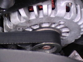

 You should have plenty of electrical right now to back it up unless you have a light bar or winch or something you should have a really good electrical setup the way it is now. How much fun was it to get that alt out of there? Mine was a real pain for the bottom bolt with that AC line right in the way.