2006 Trailblazer EXT 4.2L 2WD LS.
A little over a year ago, I hit a bump on the road, and my speedometer started moving erratically. After a few days, the speedometer only reads zero. it came back and danced around for a bit a few days later. It hasn't moved since. I had other problems with the gauges in the instrument panel (some gauges were stuck), so I assumed it was the gauges.
Recently I took the instrument panel out, and replaced all the gauges / lamps. Everything works as expected, except the speedometer, it still reads zero.
I should mention that the cruise control always worked, and still works.
So I started snooping around;
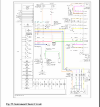
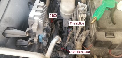
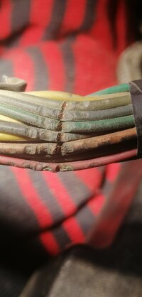
looking at the wiring diagram of the car, the VSS signal comes from the PCM, and then splits to different destinations. The wiring diagram says "I/P harness, 8.5 CM from C100 breakout".
My questions are;
I've attached the wiring diagram of the instrument panel, and the oscilloscope reading from the VSS wire at different speeds.
Thanks you 😽
A little over a year ago, I hit a bump on the road, and my speedometer started moving erratically. After a few days, the speedometer only reads zero. it came back and danced around for a bit a few days later. It hasn't moved since. I had other problems with the gauges in the instrument panel (some gauges were stuck), so I assumed it was the gauges.
Recently I took the instrument panel out, and replaced all the gauges / lamps. Everything works as expected, except the speedometer, it still reads zero.
I should mention that the cruise control always worked, and still works.
So I started snooping around;
- The VSS wire that feed the speed to the instrument panel also goes to the radio. there is no continuity between them. (I should say that the radio doesn't have sound, it could be the amplifier, but i didn't check).
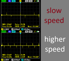
- I attached wires to the back of the instrument panel plug, my oscilloscope only reads oscillations on the VSS wire in the mV range (also not a square wave just spikes). It reads the engine speed just fine where the signal is at 12V.
- The VSS wire doesn't short to ground (no continuity between them).
- I disconnected the instrument panel, and attached a function generator to the VSS pin on the instrument panel, and the speedometer works (1hz/mile, 6hz/10km). I also attached it to the Engine rev meter pin and it works as well (33hz/1000rpm). So I know the instrument panel works.
looking at the wiring diagram of the car, the VSS signal comes from the PCM, and then splits to different destinations. The wiring diagram says "I/P harness, 8.5 CM from C100 breakout".
My questions are;
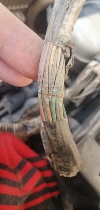
- where is this splice located (what is C100 breakout)?
- How would you go about testing whether the PCM is sending a signal on the VSS wire or not? (I want to rule out faulty PCM).
I've attached the wiring diagram of the instrument panel, and the oscilloscope reading from the VSS wire at different speeds.
Thanks you 😽