What are your resources here? I scanned through your posts here and found no mention of a multimeter. I did see a comment about acquiring a scantool? Any chance you have one of those inexpensive bluetooth or wifi OBD2 adapters that work with a phone app? Do you own an Android device (phone or tablet)??
I am a tinkerer. I am cursed with a curiosity of how things work. Couple this with a background that gave me a strong foundation in mechanical and electrical devices. I bought a TrailBlazer in late 2010 and have been studying whatever I got into since then. Eventually I became active in online sites and read various posts from owners having troubles. In an effort to help where I could I began buying parts at auto recycling yards for study. I have a couple of test bench setups with various devices like PCM, BCM, IPC, TCCM, etc.
Yesterday for example I documented the possible Passlock signal voltage ranges for each passlock code of 0 to 12. The BCM assigns a Passlock code of 0 to 12 reported at PID 221C. The Passlock signal voltage is at PID 2117. FWIW the 'key in ignition' sataus is reported at bit 0 of PID 2101. I have never come across any post or publication where this is presented. From this I worked out resistance values that would be best for a bypass if one were to go that route. I began that experiment to see if any codes get set when a Passlock system is bypassed in this way.
The Passlock signal, code, and 'key in ignition' status' can be monitored with a phone app and the proper user-entered PID setup which I can provide.
When all the hype is stripped away the Passlock circuit is a very basic thing. A sensor, a BCM and 3 wires between them.
When the BCM wakes up it provides 12 volts to power the sensor circuitry. That's 2 of the theee wires. On the 3rd wire (yellow) the BCM sends out a weak (current limited) 5 volt signal. When the ignition cylinder is rotated to the START position the sensor connects a resistor between the weak 5 volt signal (yellow wire) from the BCM to ground. Connecting a resistor to ground like this drops that 5 volt signal lower, but not too low. The BCM is reading this voltage and checking that this voltage matches the value that the BCM stores in memory. If the voltage signal matches then you are all good for startup. If it doesn't then you most likely get a security light and code.
ANY poor connection in any of the 3 wires will almost certainly cause a fault.
Less likely but possible would be a failure of the sensor to read the rotation of the ignition lock cylinder and then not connect the resistor to ground. There is a small magnet in the rotating key cylinder. This is what the sensor senses, the magnetic field of this small magnet in the rotating key cylinder. If the cylinder to lock housing has gotten very loose I can imagine it may lead to such a fault though I haven't seen it myself.
Some images just for familiarity sake:
First we have the ignition lock cylinder with the small magnet circled. Above the cylinder in the picture is a passlock sensor still in the plastic housing, the area where the magnet is sensed is circled. Above that is the circuit card of the sensor after the plastic housing is stripped away. The semiconductors that do the actual sensing are circled.
View attachment 109662
Next is an image displaying the alignment of cylinder to sensor when installed in the lock housing. The sensor is stationary, the cylinder moves the magnet into this position at START.
View attachment 109661
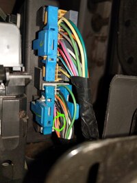
Here we have a lock housing with Passlock sensor. One can see the three wire connector. One can also see the sensor is not meant to be removeable. It will almost certainly be ruined in any attempt to remove it. Also in this image though mostly out of view is the "key in ignition" switch. It is the off white plastic thing directly behind the 3 wires coming out of the Passlock sensor harness connector.
View attachment 109663
. Last image is another view of a stripped out passlock sensor with the actual resistor responsible for the voltage signal read by the BCM circled.
View attachment 109664


 Or does this indicate a different problem or identify one maybe? Nothing ever works right for me.