The most frequent question that people ask me when it comes to LED mods, is "how do you know what resistor(s) to use?"
With this write up, (on the assumption you are already familiar with soldering) I hope to answer some of those questions and shed some light on the options that are available to people wanting to learn and perform LED mods on their vehicle but aren't sure where to start.
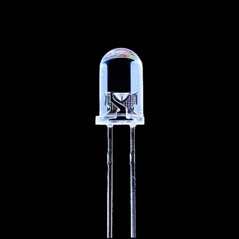
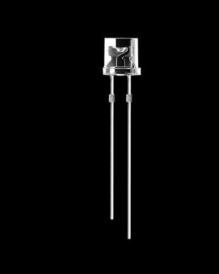
First off, you'll want to figure out the size, color, and shape of the LEDs you want to use. For most of the mods I've seen performed, 5mm is the size of choice. You can also use 3mm, or some of the larger sized bulbs depending on the mod you have in mind. The 2 dominant bulb shapes are round tops, and flat tops. Flat tops tend to have a wider beam pattern, so I recommend those. The best deals are usually Ebay vendors in China. The downside is the wait time for your package. Pictured here, the longer leg is the positive lead, the shorter one is the negative.
If you run a quick Google search, you will come up with a pretty good list of LED resistor calculators, that will all essentially ask you for the same pieces of information. Supplied voltage (output from your alternator), LED current (the current your LEDs can take) and voltage drop (the voltage the LEDs use)
When you find an Ebay ad (or from any other seller) that suits your needs, scroll down to the Details section and you should see information listed that's similar to this ad from a batch that I purchased. The 2 requirements for an LED resistor calculator have been boxed.
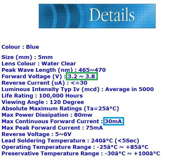
Pulling up the resistor calculator, you input the numbers. First example is calculating the resistor needed for this particular LED in a single setup. I have seen my alternator put out 14.5V max, so I always use this number as my supply voltage. From the Ebay ad, it lists the Forward Voltage in a range from 3.2V to 3.8V so I averaged that to 3.5V and enter that. The continuous current is 30 milliamps. Running the calculator spits out the exact resistance (ohms and wattage) and then a rounded value.
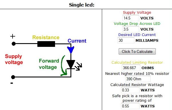
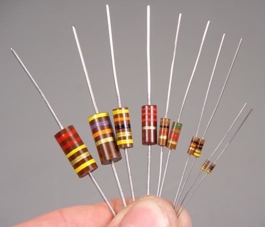
Depending on where you look for resistors, you may find a value available that's close to the calculated one. Anything within the calculated to rounded range would be fine. In this case a 366 ohm 1/3 watt to a 390 ohm 1/2 watt resistor would do the trick.
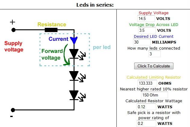
Taking this one step further, if you have multiple LEDs, you can string them in series (back to back). Doing this allows you to use fewer resistors and conserve space. Generally you can max out at 3 LEDs together before you run out of voltage to supply the circuit. So if we apply the same numbers for a 3 LED set we get the following. Between a 133 ohm 1/8 watt and 150 ohm 1/4 watt resistor.
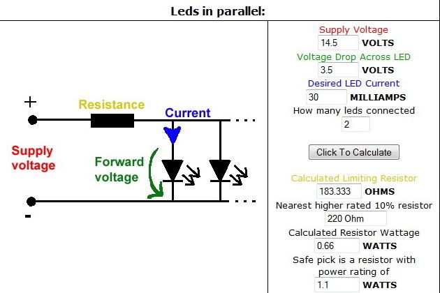
The same logic applies for wiring up the LEDs in parallel with each other, receiving power from the resistor without the voltage drop from another LED in front of it.
So if you have a 3 LED mod, you can wire them up with any of the above methods. 1 resistor per LED, or 1 lower rated resistor for all 3 LEDs if you wire them like the diagrams. Once you've got a handle on that, you can step your game up and get into LED arrays. Doing this combines the last 2 steps, taking sets of LEDs in series, and wiring those up in parallel with each other. This comes in handy when you're dealing with a large number of LEDs, for instance creating dome light circuit boards.
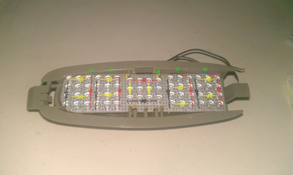
Here's the cargo light that I made containing 60 blue 5mm flat top LEDs. I took sets of 3 LEDs in series, and wired them in groups of 4 in parallel with each other, and put a resistor in front of that group. Duplicated that 5 times on the circuit board, and connected the pre-resistance lead to the positive source for the light's socket. The location of the resistors is marked by a green star, the red line/arrow indicates the flow of power from the resistor to the beginning of the LED array. The yellow line/arrow indicates the flow of voltage down through each series of 3 set of LEDs, and they join to a common ground which ties to the negative lead for the light.
The formula for the resistance needed for the array is as follows:
_________1___________
(1/R1)+(1/R2)+(1/R3)+...
where R1, R2, etc is the resistance needed for the set of LEDs in series. So to go back to the previous examples, a set of 3 LEDs in series requires a 150 ohm 1/8 watt resistor. Plugging that into the formula gives you about a 37ohm resistor. To make this a lil easier, I preloaded an Excel sheet into a zip file with this formula, with combinations of up to 10 parallel sets of LEDs in series for anyone to use. It can be tweaked to input different resistance levels, so if you had multiple sets of 3 LEDs in series, some sets of 2 LEDs in series, single LED/resistor combos, or combinations of all of the above, the same logic applies. Whatever resistance needed for that 'in series set', can be entered and the ohm rating will be calculated for you.
If there's anything I missed or overlooked, any of the other experienced LED folks can feel free to chime in and add anything. If anyone has any questions, post em up and we'll try to get them answered and your mod bug properly fed.

With this write up, (on the assumption you are already familiar with soldering) I hope to answer some of those questions and shed some light on the options that are available to people wanting to learn and perform LED mods on their vehicle but aren't sure where to start.
First off, you'll want to figure out the size, color, and shape of the LEDs you want to use. For most of the mods I've seen performed, 5mm is the size of choice. You can also use 3mm, or some of the larger sized bulbs depending on the mod you have in mind. The 2 dominant bulb shapes are round tops, and flat tops. Flat tops tend to have a wider beam pattern, so I recommend those. The best deals are usually Ebay vendors in China. The downside is the wait time for your package. Pictured here, the longer leg is the positive lead, the shorter one is the negative.


If you run a quick Google search, you will come up with a pretty good list of LED resistor calculators, that will all essentially ask you for the same pieces of information. Supplied voltage (output from your alternator), LED current (the current your LEDs can take) and voltage drop (the voltage the LEDs use)
When you find an Ebay ad (or from any other seller) that suits your needs, scroll down to the Details section and you should see information listed that's similar to this ad from a batch that I purchased. The 2 requirements for an LED resistor calculator have been boxed.

Pulling up the resistor calculator, you input the numbers. First example is calculating the resistor needed for this particular LED in a single setup. I have seen my alternator put out 14.5V max, so I always use this number as my supply voltage. From the Ebay ad, it lists the Forward Voltage in a range from 3.2V to 3.8V so I averaged that to 3.5V and enter that. The continuous current is 30 milliamps. Running the calculator spits out the exact resistance (ohms and wattage) and then a rounded value.

Depending on where you look for resistors, you may find a value available that's close to the calculated one. Anything within the calculated to rounded range would be fine. In this case a 366 ohm 1/3 watt to a 390 ohm 1/2 watt resistor would do the trick.
Taking this one step further, if you have multiple LEDs, you can string them in series (back to back). Doing this allows you to use fewer resistors and conserve space. Generally you can max out at 3 LEDs together before you run out of voltage to supply the circuit. So if we apply the same numbers for a 3 LED set we get the following. Between a 133 ohm 1/8 watt and 150 ohm 1/4 watt resistor.

The same logic applies for wiring up the LEDs in parallel with each other, receiving power from the resistor without the voltage drop from another LED in front of it.

So if you have a 3 LED mod, you can wire them up with any of the above methods. 1 resistor per LED, or 1 lower rated resistor for all 3 LEDs if you wire them like the diagrams. Once you've got a handle on that, you can step your game up and get into LED arrays. Doing this combines the last 2 steps, taking sets of LEDs in series, and wiring those up in parallel with each other. This comes in handy when you're dealing with a large number of LEDs, for instance creating dome light circuit boards.
Here's the cargo light that I made containing 60 blue 5mm flat top LEDs. I took sets of 3 LEDs in series, and wired them in groups of 4 in parallel with each other, and put a resistor in front of that group. Duplicated that 5 times on the circuit board, and connected the pre-resistance lead to the positive source for the light's socket. The location of the resistors is marked by a green star, the red line/arrow indicates the flow of power from the resistor to the beginning of the LED array. The yellow line/arrow indicates the flow of voltage down through each series of 3 set of LEDs, and they join to a common ground which ties to the negative lead for the light.

The formula for the resistance needed for the array is as follows:
_________1___________
(1/R1)+(1/R2)+(1/R3)+...
where R1, R2, etc is the resistance needed for the set of LEDs in series. So to go back to the previous examples, a set of 3 LEDs in series requires a 150 ohm 1/8 watt resistor. Plugging that into the formula gives you about a 37ohm resistor. To make this a lil easier, I preloaded an Excel sheet into a zip file with this formula, with combinations of up to 10 parallel sets of LEDs in series for anyone to use. It can be tweaked to input different resistance levels, so if you had multiple sets of 3 LEDs in series, some sets of 2 LEDs in series, single LED/resistor combos, or combinations of all of the above, the same logic applies. Whatever resistance needed for that 'in series set', can be entered and the ohm rating will be calculated for you.
If there's anything I missed or overlooked, any of the other experienced LED folks can feel free to chime in and add anything. If anyone has any questions, post em up and we'll try to get them answered and your mod bug properly fed.


 I agree with Larry, I use an old computer power supply with some alligator clips, as my test bench, since I happened to have one laying around in an old parts bin. If you want to go that route, let me know and I'll tell you how to tweak it so that works for you. But a 9V battery would work just to make sure your connections are good, and voltage is flowing through your circuit.
