How to change a stepper motor

Blacktrails

Original poster
Member
Dec 8, 2011
34
Summary: Replacing a bad stepper motor.


Difficulty: Moderate to Difficult
Estimated Time: 1-2 hours, start to finish, depending on soldering skills.
Part Numbers: X-C5-168 (oldest), X-25-168 (newer) X-27-168 (latest)
Cost: $5.00-$10.00 per stepper motor
Equipment needed: 7mm socket
Phillips head screwdriver
Flat head screwdriver
Soldering iron & Solder

Step 1) Remove dash panel: Due to the fact that this can repair can be done on so many different GM vehicles, I am not going to explain how to do this step.

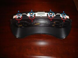
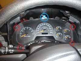
Step 2) Remove gauges: Begin by removing 4 7mm bolts (A) located at the four corners of the gauge cluster.
Next, pinch the blue wire harness (B) and pull out.
View attachment 17423

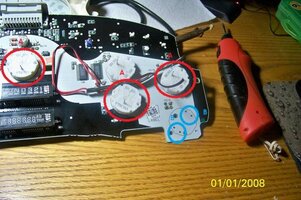
Step 3) Disassemble gauge cluster: The clear plastic part is the first piece to be removed. Push down on the plastic tabs (A) with your thumbs while simultaneously pushing out. Next use the flat head to pry the back clips (B) from the rest of the cluster. This may take some finesse as once you pry a few free and move on to the next side, the previous clips may refasten.
View attachment 17419

Step 4) Remove needles:Carefully remove the needles using a fork underneath each needle. It will take some force but they will come off. Be careful not to twist while pulling on the needles. Take note as to where the needles point so you can replace them in the same spot.

Step 5) Locating circuit board: Once the needles are removed simply pull the cluster apart to reveal the circuit board.

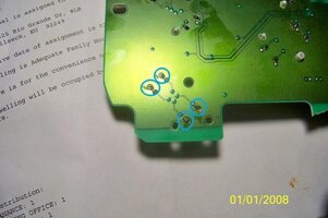
Step 6) Remove stepper motor: These are what the stepper motors look like (A). They are soldered at 4 points on the back (B).
View attachment 17421

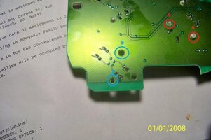
Step 7) Solder new stepper motor. The stepper motor has 2 posts in the back (A). These posts line up with the 2 bigger holes (B) in the circuit board. They only go in one way so there is no fear of soldering the wrong leads to the wrong place. Once the motor is in place, simply solder the 4 leads in place.
View attachment 17422

That's it. Once you have soldered the new motor in just reassemble the gauge cluster in the reverse order that you disassembled it and re install it into the truck. Again take care of lining up the needles correctly in order to save yourself headache later. I recommend, leaving the clear plastic off and installing the gauges. Start the truck to be sure that the needles are aligned properly. This way, if they're not aligned you don't have to remove anything to fix them.
 

Attachments

  • pic2.jpg
    pic2.jpg
    50.4 KB · Views: 367
  • 100_5382.jpg
    100_5382.jpg
    56.8 KB · Views: 45
  • 100_5383.jpg
    100_5383.jpg
    32.4 KB · Views: 44
  • 100_5383 (3).jpg
    100_5383 (3).jpg
    32.5 KB · Views: 46
  • pic1.jpg
    pic1.jpg
    88.8 KB · Views: 366

christo829

Member
Dec 7, 2011
513
Fairfax, Virginia
Hi CavScout1836! Thanks for the write up!

Thought that I'd point out that the XC5168 motors are the oldest ones, and the ones that seem
to have most of the problems.

The newer ones are the X25168 motors. When I replaced my steppers, these are the ones I used,
and so far they're doing nicely.

Now, as FFMikeM has pointed out, there are even newer motors, # X27168.

Just thought perhaps that ought to be noted someplace in the write up.

Cheers-

Chris
 

MAY03LT

Member
Nov 18, 2011
3,426
Delmarva
christo829 said:
Thought that I'd point out that the XC5168 motors are the oldest ones, and the ones that seem
to have most of the problems.

The newer ones are the X25168 motors. When I replaced my steppers, these are the ones I used,
and so far they're doing nicely.

Now, as FFMikeM has pointed out, there are even newer motors, # X27168.

Just thought perhaps that ought to be noted someplace in the write up.

CavScout, if you're ok with these part numbers being added to the original post let us know.:cool:
 

gmcman

Member
Dec 12, 2011
4,660
Would these work on the 2002 model? Doesn't show compatibility but aren't they the same?
 

Kage_

Member
Dec 29, 2011
4
I saw a tip with the alignment of the needles.

Once you have the front cover off take a little masking tape and place a piece under each needle at it's tip. With a pen or small sharpie make a mark indicating where the needle position currently is. Once the motor has been replaced and the needle reinstalled it can then be rotated counter clockwise lining it up with the mark that was made before it was removed.

You can prob eye ball the needles, but I'm a little on the anal retentive side so I want them back in exactly the same place they were.

Kage_
 

Sparky

Member
Dec 4, 2011
12,927
But how do you know the new motors are in the exact same position as the originals? :confused:
 

Blacktrails

Original poster
Member
Dec 8, 2011
34
MAY03LT said:
CavScout, if you're ok with these part numbers being added to the original post let us know.:cool:

Yes, please include those part numbers. I had gotten those numbers from the OS. I had a spare cluster so I just used the motors off of that one.


Sparky said:
But how do you know the new motors are in the exact same position as the originals? :confused:

The motors will only fit one way. You cant put it in backwards :thumbsup:
 

Sparky

Member
Dec 4, 2011
12,927
CavScout1836 said:
Yes, please include those part numbers. I had gotten those numbers from the OS. I had a spare cluster so I just used the motors off of that one.


The motors will only fit one way. You cant put it in backwards :thumbsup:

I meant the spindle position of the motor (what the needle presses on to), not the orientation of the motor on the circuit board.
 

Blacktrails

Original poster
Member
Dec 8, 2011
34
Im confused (easily done). If you talking about whether the spindle is at the 10 oclock, 6 oclock ect, position, then the posts on the back of the motors will line that up for you. I promise that you can not screw up the position of the motors or the spindles. :thumbsup:
 

nospark

Member
Feb 20, 2012
28
Hazelwood MO
I'm still trying to comprehend the needle placement. My fuel, oil, and voltage gauges point at random locations every time I turn on key. Gas gauge goes almost around to empty after filling up. Nice having DIC to help. If I put the neddles back on at the last location, will the new motors find the correct location when I'm finished. And to add, they don't go to zero when turned off now. Thanks
 

gmcman

Member
Dec 12, 2011
4,660
I had the same issue when I was replacing my needles as well. With the plastic cover off, place the cluster in its place behind the wheel and reconnect the harness.

Very lightly place the needles back on then start the engine. Verify ccorrect needle placement and if then need to be moved, be very, very careful to not turn the needle. If the motor shaft is turned it will reset its normal position on restart, changing the needle orientation.
 

nospark

Member
Feb 20, 2012
28
Hazelwood MO
Thank you and does the tach also have a stepper motor? Can't see in pics. Great article with pics btw. My temp gauge and tach work fine. everything else is screwy. Speedo works, has fadded away 2 times. If thinking replace it all while apart?
 

gmcman

Member
Dec 12, 2011
4,660
They all have stepper motors, if you are good with soldering then I would replace all that are at least giving you troubles.
 

Jimbo052

Member
Feb 29, 2012
38
Kage_ said:
I saw a tip with the alignment of the needles.
Once you have the front cover off take a little masking tape and place a piece under each needle at it's tip. With a pen or small sharpie make a mark indicating where the needle position currently is. Once the motor has been replaced and the needle reinstalled it can then be rotated counter clockwise lining it up with the mark that was made before it was removed.
Kage_

This is almost completely correct, but leaves out a key detail. After removing the cover, move all the needles counterclockwise until the needles reach the hard stop. Then put down the tape and mark the positions of the needles. I would suggest replacing all the stepper motors while you're in there because bending the shafts of the stepper motors can't really be avoided. (Quite a bit of force is needed to get the needles to slide off the shaft.)

It is important to understand that the motors only have a working range of roughly 180 degrees. (Not sure on the actual range.) If you take apart one of the old motors, you'll see that there are two physical stops inside the motor that will limit the needle's motion. One stop is the zero position, and the other is the max position.

Once you put the needles back on, you have to align the needle on the shaft so that when rotating counterclockwise the needle reaches its hard stop at the mark you made previously. If the needle doesn't line up, you can spin the needle to one of its limits and continue rotating whatever distance you need so that the needle will land on your mark when rotated counterclockwise.

So I guess my point is that just setting the needle in the position it was previously is not enough. The needle must be set in the same position on the shaft as well as on the mark you made.

I have done this fix on my Trailblazer, so if anyone has any specific questions, let me know. I'd be glad to help. :thumbsup:
 

MMIN

Member
Feb 26, 2012
55
Just one extra tip for anyone that wants to try this. You still want to mark the locations, but also - take your phone and take a picture of the cluster beforehand, then turn the key on without starting and take another picture. Having those two pictures to see the needles are great to have!
 

Sparky

Member
Dec 4, 2011
12,927
That's the piece that was missing. I didn't know they had the hard stops in them, so I was trying to figure out how they'd line up. Makes sense now :thumbsup:
 

Jimbo052

Member
Feb 29, 2012
38
I believe it's always easier to watch someone else do something before I tackle a project, so here are a few videos:

Gage cluster repair from start to finish (Stepper motors only):
[video=youtube;gWELz904fj0]http://www.youtube.com/watch?v=gWELz904fj0[/video]

Gage cluster repair from start to finish (Light bulbs only):
[video=youtube;fC_dE0iZtxE]http://www.youtube.com/watch?feature=iv&src_vid=gWELz904fj0&annotation_id=annotation_684880&v=fC_dE0iZtxE#t[/video]

Hope these help! :thumbsup:

BTW, all credit goes to Trunk37 from YouTube for these awesome videos.
 
Dec 4, 2011
520
This is awesome. I hope I never have to use this information but if I do I will know where to go. As a supporter of this site this is why I do it. The little I give is repaid hundreds of times over.

:thumbsup::thumbsup::smile:
 

Jimbo052

Member
Feb 29, 2012
38
Can we get the article updated with some of this information and maybe links to these videos?
 

nospark

Member
Feb 20, 2012
28
Hazelwood MO
Thanks to CavScout 1836 for the first set of pics and Jimbo 052 for the info on the hard stops. I fixed mine over the week end. Knowing of the hard stops gave me a starting point to mark the tape with on the gauges that was way out of whack. There not exactly were they were before but close enough on temp, volt, oil pres., fuel looked close based of what the DIC was telling me. I did tweak the tach. because I don't think it idles at 1100 rpm when at full temp. One thing that was useful for the speed is that I have a GPS that would read exactly the same as my speedo, which the speedo was not giving me issues except an occasional not wake up on cold mornings. Before pressing the speedo needle all the way on, I took a drive down highway, lock cruise when the gps was steady at 60, and observing the needle. it was approx. 3 mph fast. Reset needle on off ramp, circled back towards house and it was dead on. Went home and finished putting it back together. About 2 hours taking my time for all 6 motors. Thanks again. Sorry not good with taking pics, I couldn't do as good as the ones here now.
 

Code Red

Member
Dec 11, 2011
377
Guess I'll be doing this :-(

67355_10151346075155783_627942015_n.jpg

12255_10151346365770783_1624517073_n.jpg
 

Forum Statistics

Threads
23,676
Posts
641,849
Members
19,114
Latest member
SCr

Members Online