Fog Light DRL Mod
Overview:
Alright guys here is a simple way to convert your fogs into DRL. We will accomplish this by using a combination of a capacitor and relay spliced into the wiring at the BCM. This mod keeps the auto headlight function, so when it gets dark the fog lights will turn off and the headlights will turn on. In addition to the fogs being on during the day, they will also become the front night time perimeter illumination while remote unlocking. This is for vehicles that have factory fog lights, but can be modified to work with other lights by adding an additional relay.
Summary: Turning the fog lights in to Daytime Running Lights (DRL)
Difficulty: Moderate
Estimated Time: 30-45 min
Total Cost: $10-$20
Required tools:
10mm Socket
Ratchet for Socket
Wire stripper/cutter
Crimper
Soldering Iron
Solder
Heat Shrink Tubing
1x 10uf 35v Capacitor
1x Blue Ring Terminal
2x Red Butt Connectors
3x Red Scotch Lock Connector
1x Blue Scotch Lock Connector
5x Female Spade Connectors (If not using a relay socket)
1x 5pin relay, preferably with relay socket to make installation cleaner
7x Random lengths of wire (I used roughly 10" of wire that is color coded to the BCM wires we will be working on)
Note: Being we are going to be working on the bcm connectors, if you are not comfortable with electrical wiring then find someone who is comfortable doing it. The author takes no responsibility if you mess up the wiring, or worse yet the bcm. Also as like any electrical modifications, DISCONNECT battery before preforming any work on the electrical system.
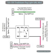
We will be using this diagram to install the relay into the wires at the BCM.
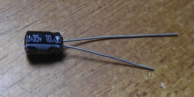
Before we head out to the vehicle, lets get our capacitor soldered up and make sure our relay is ready to go. The capacitor has negative and positive leads(most capacitors have a negative marking on the side, if not usually the shorter lead is negative), so be sure to remember which wire is positive and negative(I used red for positive, black for negative). Solder the red wire to the positive lead of the capacitor, and the black wire to the negative lead of the capacitor, then heat shrink each solder joint, and then i used the next size up and just heat shrinked over the capacitor and the joints.
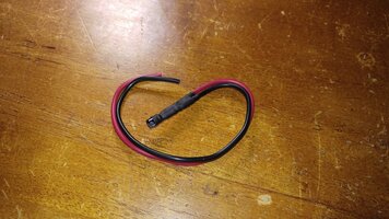
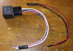
Once all soldered connections are done, and if you are not using a relay socket, now would be the time to install the female spade connectors onto the wires for the relay and to get ready to head out to the vehicle for installation.
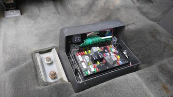
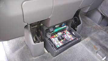
1. Once out at the vehicle we have to access the BCM. Short wheelbase models will need to pull up on the rear driver side seat to expose the fuse box cover, and then remove the cover off the fuse box and BCM. Long wheelbase models will need to remove the driver side second row seat to gain enough access to the BCM, once the seat is removed you will be able to take the cover off of the fuse box to access the BCM (Which is what I had to do since I have a LWB).
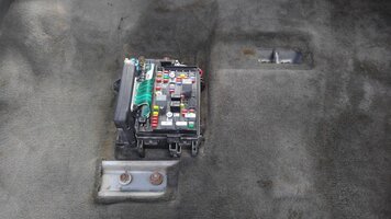
2. Once we have access to the BCM its time to disconnect both plugs on the side of the BCM (a gray plug, and a tan plug). From here you will need to remove some of the tape around the wires to give you enough room to cut and tap into the wires we need to(LWB models may not have extra wire to work with, so it might be pretty close to the BCM Connectors. Just make sure you give yourself enough room for the connector being used).
3. Find the pink/white wire in pin A5 of the gray plug. Follow the wire back about 3-4 inches and CUT then strip the ends of each of the wires, I also installed a red butt connector on each end of the wires.
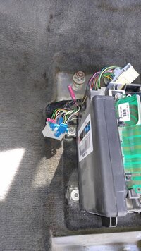
4. Next we will connect the pink/white wire from pin #30 to the pink/white wire that comes from the BCM Connector. Then we will connect the pink/white wire from pin #87 to the pink/white wire that goes into the wire harness.
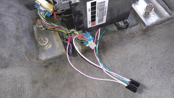
5. Next we will find the white wire in Pin B6 of the gray plug. Follow the wire back about 3-4 inches away from the plug and use the red scotch lock to connect the white wire from pin #86 of the relay
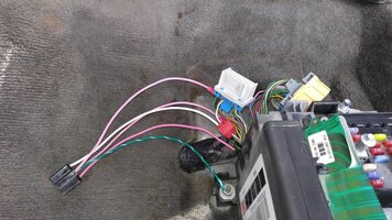
6. Next we will find the Pink wire in pin E7 of the tan plug. Follow the wire back about 3-4 inches away from the plug and use the red scotch lock to connect the pink wire from Pin #85 of the relay.
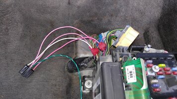
7. Next we will find the Dark Green/White wire in Pin E11 of the tan plug. Follow the wire back about 3-4 inches away from the plug and use the last red scotch lock to connect the drk green/white wire from Pin #87a of the relay
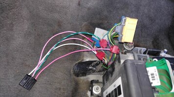
8. Now its time to connect the capacitor, first lets take the positive end and using a scotch lock connect it to the pink/white wire that goes to pin #30 of the relay.
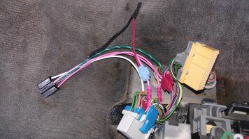
9. Using a 10mm socket, remove one of the nuts that holds the fuse box to the vehicle. Install a ring terminal on the negative end of the capacitor, and install the ring terminal on the stud that you removed the nut from. Reinstall the nut tight so we have a good solid ground. If using a relay socket, you can now install relay into socket.
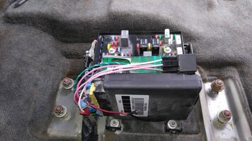
If you don't have a helper to see if everything is working the way it should, then block your wheels so when you put the vehicle into gear to check for proper operation it wont roll.
10. Once all connections are made, and you either have a helper or the wheels blocked. Reconnect the battery, turn the ignition to run and move the shifter out of park. Check to make sure the fog lights have came on. If they do, put shifter back into park and turn ignition off.
11. Time to button everything up and reinstall the seat if you have a long wheel base.
12. Step back, crack open a beer and enjoy a job well done!
Overview:
Alright guys here is a simple way to convert your fogs into DRL. We will accomplish this by using a combination of a capacitor and relay spliced into the wiring at the BCM. This mod keeps the auto headlight function, so when it gets dark the fog lights will turn off and the headlights will turn on. In addition to the fogs being on during the day, they will also become the front night time perimeter illumination while remote unlocking. This is for vehicles that have factory fog lights, but can be modified to work with other lights by adding an additional relay.
Summary: Turning the fog lights in to Daytime Running Lights (DRL)
Difficulty: Moderate
Estimated Time: 30-45 min
Total Cost: $10-$20
Required tools:
10mm Socket
Ratchet for Socket
Wire stripper/cutter
Crimper
Soldering Iron
Solder
Heat Shrink Tubing
1x 10uf 35v Capacitor
1x Blue Ring Terminal
2x Red Butt Connectors
3x Red Scotch Lock Connector
1x Blue Scotch Lock Connector
5x Female Spade Connectors (If not using a relay socket)
1x 5pin relay, preferably with relay socket to make installation cleaner
7x Random lengths of wire (I used roughly 10" of wire that is color coded to the BCM wires we will be working on)
Note: Being we are going to be working on the bcm connectors, if you are not comfortable with electrical wiring then find someone who is comfortable doing it. The author takes no responsibility if you mess up the wiring, or worse yet the bcm. Also as like any electrical modifications, DISCONNECT battery before preforming any work on the electrical system.
We will be using this diagram to install the relay into the wires at the BCM.

Before we head out to the vehicle, lets get our capacitor soldered up and make sure our relay is ready to go. The capacitor has negative and positive leads(most capacitors have a negative marking on the side, if not usually the shorter lead is negative), so be sure to remember which wire is positive and negative(I used red for positive, black for negative). Solder the red wire to the positive lead of the capacitor, and the black wire to the negative lead of the capacitor, then heat shrink each solder joint, and then i used the next size up and just heat shrinked over the capacitor and the joints.


Once all soldered connections are done, and if you are not using a relay socket, now would be the time to install the female spade connectors onto the wires for the relay and to get ready to head out to the vehicle for installation.

1. Once out at the vehicle we have to access the BCM. Short wheelbase models will need to pull up on the rear driver side seat to expose the fuse box cover, and then remove the cover off the fuse box and BCM. Long wheelbase models will need to remove the driver side second row seat to gain enough access to the BCM, once the seat is removed you will be able to take the cover off of the fuse box to access the BCM (Which is what I had to do since I have a LWB).

2. Once we have access to the BCM its time to disconnect both plugs on the side of the BCM (a gray plug, and a tan plug). From here you will need to remove some of the tape around the wires to give you enough room to cut and tap into the wires we need to(LWB models may not have extra wire to work with, so it might be pretty close to the BCM Connectors. Just make sure you give yourself enough room for the connector being used).
3. Find the pink/white wire in pin A5 of the gray plug. Follow the wire back about 3-4 inches and CUT then strip the ends of each of the wires, I also installed a red butt connector on each end of the wires.

4. Next we will connect the pink/white wire from pin #30 to the pink/white wire that comes from the BCM Connector. Then we will connect the pink/white wire from pin #87 to the pink/white wire that goes into the wire harness.

5. Next we will find the white wire in Pin B6 of the gray plug. Follow the wire back about 3-4 inches away from the plug and use the red scotch lock to connect the white wire from pin #86 of the relay

6. Next we will find the Pink wire in pin E7 of the tan plug. Follow the wire back about 3-4 inches away from the plug and use the red scotch lock to connect the pink wire from Pin #85 of the relay.

7. Next we will find the Dark Green/White wire in Pin E11 of the tan plug. Follow the wire back about 3-4 inches away from the plug and use the last red scotch lock to connect the drk green/white wire from Pin #87a of the relay

8. Now its time to connect the capacitor, first lets take the positive end and using a scotch lock connect it to the pink/white wire that goes to pin #30 of the relay.

9. Using a 10mm socket, remove one of the nuts that holds the fuse box to the vehicle. Install a ring terminal on the negative end of the capacitor, and install the ring terminal on the stud that you removed the nut from. Reinstall the nut tight so we have a good solid ground. If using a relay socket, you can now install relay into socket.

If you don't have a helper to see if everything is working the way it should, then block your wheels so when you put the vehicle into gear to check for proper operation it wont roll.
10. Once all connections are made, and you either have a helper or the wheels blocked. Reconnect the battery, turn the ignition to run and move the shifter out of park. Check to make sure the fog lights have came on. If they do, put shifter back into park and turn ignition off.
11. Time to button everything up and reinstall the seat if you have a long wheel base.


12. Step back, crack open a beer and enjoy a job well done!
Last edited:


 .
.


